Beam 9602 Instruction Manual

9602 SBD Modem
Short Burst Data Modem
Installation & User Manual
Beam Communications Pty Ltd
www.beamcommunications.com

www.beamcommunications.com
2
9602 SBD Modem | Installation and User Manual
9602 SBD Modem
Installation and User Manual
GLOBAL HEAD OFFICE
8 Anzed Court
Mulgrave, Victoria,
Australia, 3170
Information furnished by Beam Communications Pty Ltd (Beam) is believed to be accurate and
reliable. However, no responsibility is assumed by Beam for its use, or for any infringement of
patents or other rights of third parties, which may result from its use. No license is granted by
implication or otherwise under any patent or patent rights of Beam. Beam reserves the right to
change specications at any time without notice.
Copyright © 2011 Beam Communications Pty Ltd. All rights reserved
Product name: 9602 SBD Modem Installation & User Manual
Manual revision: 01
Part Number USRMAN007501
Issue Date: November 2011

www.beamcommunications.com
9602 SBD Modem | Installation and User Manual 3
User / Installer Information
Please record your serial number here for future reference:
Model: 9602 SBD MODEM
Serial no.:
This number can be copied from the white shipping label on the 9602 SBD MODEM box Eg. SB202833
Installation Location: Installation Date:
Installation Technician: Place Of Purchase:

www.beamcommunications.com
4
Content
User / Installer Information 3
Equipment Overview 5
About BEAM Communications 6
Conventions in this Manual 7
Safety Information 7
What is the 9602 SBD Modem? 8
Package Contents 8
Optional BEAM Accessories 8
Installing the 9602 SBD Modem 9
Connecting the antenna cable 9
Connecting the power and IO cables and USB cable 10
How to Mount the 9602 SBD Modem 11
Installing the USB Drivers 12
Dimensions 15
Specication Summary 16
RS232 Specication 17
Physical Connection 17
RS232 Port signal support and handshaking 17
RS232 port electrical parameters 19
Data Connectivity 19
Conguration Settings 19
Modes of Operation 20
Hardware failure reporting 20
RF Interface 21
Antenna Connector 21
Antenna Connector Type 21
Radio Characteristics 21
Troubleshooting the 9602 SBD Modem 22
BEAM Warranty conditions 23

9602 SBD Modem | Installation and User Manual 5
Equipment Overview
1. USB mini-B Port
2. SMA Antenna Jack
3. LED Indicator
4. 14 pin Connector
5. SMA to TNC Adaptor
6. Mounting Bracket
Cable:
7. Serial Connector
8. 14 pin Plug
9. 4 pin Power Connector
1
2
3
4
5
7
6
8
9

www.beamcommunications.com
6
About BEAM Communications
BEAM Communications, a wholly owned subsidiary of World Reach Limited (WRR), listed on the
Australian Stock Exchange, is a world leader in design, manufacture and distribution of specialized
communications equipment for the Iridium Satellite Network.
BEAM’s commitment to be at the forefront has continued to increase its share of the global satellite
communications market. Its premium distribution network spans the world.
Recognized as a leading provider of satellite communication solutions, BEAM specializes in Voice,
Data, Tracking and customized solutions. BEAM develops innovative products and services to meet
market demands and niche applications.
BEAM’s leading edge products are deployed in a wide range of markets including Maritime,
Transport, Government, Defence, Mining, Construction, Forestry, Emergency Services, Relief Aid,
Telemetry and Rural Telephony.
Supported by a dedicated team of professionals, BEAM has developed solid relationships with its
peers and network of distributors worldwide.
Beam Communications Pty Ltd
8 Anzed Court, Mulgrave,
Victoria, 3170, AUSTRALIA
Web: www.beamcommunications.com
Info: info@beamcommunications.com
Support: support@beamcommunications.com
Tel: +61 3 8588 4500
Fax: +61 3 9560 9055

9602 SBD Modem | Installation and User Manual 7
Conventions in this Manual
Warnings, cautions and notes appear throughout this manual.
They are represented by following conventions.
Warning:
This symbol and associated text indicate a warning note providing information to prevent
personal injury or damage to equipment.
Note:
This symbol and associated text indicate a note providing general operating information.
Interference:
All wireless phones may get interference, which could aect performance.
Safety Information
Note:
Read the following information before installing and using the BEAM 9602 SBD Modem.
Your 9602 SBD Modem is a low power radio transmitter and receiver. When it is ON, it receives and
sends out radio frequency (RF) signals.
The design of your 9602 SBD MODEM system complies with international safety standards.
Refer to the appropriate section of the 9602 SBD MODEM User Manual for additional relevant safety
information.
Warning:
Do not open equipment. There are no user-serviceable parts inside.
If a DC power supply is to be used, its output must comply with the Safety Extra Low Voltage
(SELV) requirements of IEC60950.
All connectors must only be connected to equipment ports which comply with the Safety
Extra Low Voltage (SELV) requirements of IEC60950.”

www.beamcommunications.com
8
9602 SBD Modem | Installation and User Manual
What is the 9602 SBD Modem?
The 9602 SBD MODEM is a Remote Satellite Short Burst Data only modem designed to provide a
reliable and cost eective means of Iridium SBD development.
It utilizes the Iridium SBD (Short Burst Data) module and provides both D9 RS232 and USB Mini-B
connectors, for direct connection to a PC.
Key Features:
• Small form Factor
• No SIM Card Required
• Maximum mobile originated message size of 340 bytes
• Maximum mobile terminated message size of 270 bytes
• Visual indication of network availability
Package Contents
The 9602 SBD MODEM package contains:
• 1 x 9602 SBD MODEM Short Burst Data Modem
• 1 x Mounting L Bracket with attaching screw
• 1 x Power & IO Cable [CBLASY014604*]
• 1 x DC External Cable [CBLASY008003*]
• 1 x 2m USB Cable [CBLASY006701*]
• 1 x TNC-F to SMA-M coaxial adaptor [TNCF-SMAM]
• SBD9602 Quick Start Guide [USRQSG007501*]
• 1 x Resources CD (includes User Manual) [CDROM000401*]
* The last 2 digits of the part number indicate the revision. A higher number may be supplied
Optional Beam Accessories
RST710 Fixed Mast Antenna
RST715 Magnetic Mount Antenna
RST720 Bolt Mount Antenna
RST985 Serial to USB Converter Cable
See your Service Provider for pricing and availability of these optional accessories

www.beamcommunications.com
9602 SBD Modem | Installation and User Manual 9
Installing the 9602 SBD MODEM
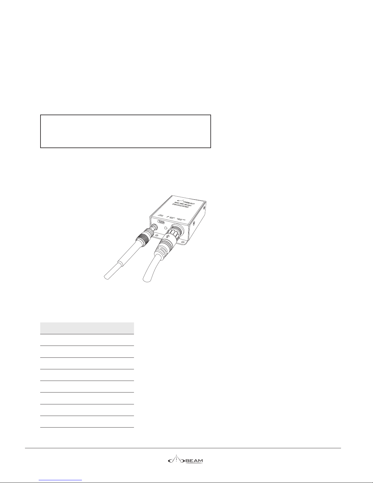
Connecting the Antenna Cable
1. Screw the TNC-F to SMA-M coaxial adaptor onto the antenna jack located on the bottom end of
the module.
2. Ensure that the cable being used is long enough to reach from the 9602 SBD MODEM to the
Antenna location. Plug the antenna cable into the adapter.
3. Ensure that you fasten the antenna cable securely to the TNC jack by screwing the cable rmly
all the way in with your ngers.
4. Please refer to the Antenna Installation Guide for important information on installation and
placement of your antenna.
Note:
Refer to the Antenna Installation Guide supplied with your 9602 SBD MODEM for
information on installing the antenna and assuring Quality of Service.
This guide is also available for download at www.beamcommunications.com
www.beamcommunications.com
10
Connecting the Power & IO Cables and USB Cable
The supplied cable, CBLASY0146 provides connection to both the power input and the 9 way RS232
serial port. The module is powered from a 9 to 32V DC supply using a 4-pin square Molex connector
from the Power & IO cable and attaching to the DC Power cable. Attach the Red and Black wires to a
compliant power supply. The RED wire is the positive. The Yellow wire is not used.
It is recommended to t a 1A or 2A fuse at the power output-end of the wire. This will protect the
wiring against re should a short circuit exist in the vehicle.
The front LED has a dual function:
Green – Power OK and network visible.
Orange – Power OK but network unavailable.
Serial communication can be either by the USB Mini-B connector or the 9 pin D Connector (RS232)
attached to the Power & IO cable. The USB port function has priority over the RS232 serial. If the USB
cable is connected to a PC it will operate and the RS232 serial will be disabled.
Both ports provide similar functionality and the setup parameters are the same for both.
The default baud rate is 19200 8N1 with hardware hand-shaking (CTS/RTS). The 9602 SBD MODEM
does not have an autobaud facility. The baud rate can be set via the AT+IPR=n where n is one of the
following.
N BAUD
1 600
2 1200
3 2400
4 4800
5 9600
6 19200 (Default)
7 38400
8 57600
9 115200
[Refer to the Iridium 9602 SBD Transceiver Product Developers Guide for other available AT commands].
Other manuals for 9602
1
Table of contents
Other Beam Modem manuals


