BECA BHP-8000 User manual

User Guide
WIFI TYPE
Welcome
Thank you for your purchase.
In the box you will find
Thermostat Screws
User Guide
1pc 4pc
2pc QC Passed 1pc
SYSTEM TYPE
FEATURES
On Appearance
2. 4.8 inch large colorful display creates your colorful life.
4. Amazing silver frame opens your modern life.
7. Wall mounted
and Italy etc,.
10. 12 terminals are available for many systems.
2. 1℉/0.5℃accuracy keeps temperature within the level you set.
3.℃or ℉choice.
4. 7 days four periods programmable.
5. Temporary programmable.
6. Holiday mode.
8. No limit to add thermostats in App.
9. Support Smart Scene.
10. Support to make two stage grouops.
11. Support device sharing.
12. Weather, UV index, humidity display help you decide what to wear today.
BHP-8000 Room Thermostat
Your new thermostat will provide uniform and comfortable temperature
control throughout every room in your peoperty. We bring together technology,
reliable product combined with sleek, contemporary design. Please read this
1. Warm air, hot water, high efficiency furnaces, heat pumps, steam, gravity.
2. Heat only--including power to open and close zone valves, and normally
open zone valves.
3. Heat only with fan.
4. Cool only.
TECHNICAL DATA
Power Supply: 24VDC/AC ±10%
Sensor: NTC3950, 10K
Set Temp. Range: 42-122℉(5~50℃)
Accuracy: ±1℉
Display Temp. Range: 41~210℉(5~99℃)
Ambient Temp: 32~113℉(0~45℃)
Ambient Humidity: 5~95%RH(Non Condensing)
Storage Temp: 23~113℉(-5~45℃)
DIMENSION
Unit: mm (inch)
Timing Error: <1%
Shell Material: PC+ABS(Fireproof)
Hole Distance of 86±3mm (USA and Italy etc,.)
Wire Terminals: Wire 2×1.5mm2 or 1×2.5mm2
INSTALLATION
For wiring , please refer to another page.
CAUTION
Electrical Shock or Equipment Damage Hazard. Can shock individuals or
short equipment circuitry.
HOME SCREEN QUICK REFERENCE
1 2
34 5 6 87 9
10
11
12
13
141516171819
20
21
22
23
24
25
26
1
Wifi(AP mode)
4
2
3
5
6
7
8
9
10
11
12
13
14
15
16
17
18
19
20
21
22
23
24
25
Wifi(EZ mode)
AUX Heat
1st Stage Heat
1st Stage Cool
Fan
Wind speed
Weather
Periods
Monday to Sunday
External sensor
Ultraviolet intensity
Outdoor Humidity
Down Button
Up Button
Clock
Permanent Hold/Temporary
Hold/Using Schedule/Hold Until (holiday)
Auto/Cool/Heat/Off/EMER
Power on/off
Time Display
Set temp.
Menu
Room Temp.
Fan On/Auto
System mode
26
Lock/Unlock
27
27
Filter Reminder
COOL — Thermostat controls the cooling system.
EMER — Emergency heat cycles to maintain temperature. Compressor is
locked out (used only for 2H/1C or 3H/2C heat pump systems) and auxiliary
heat turns on as second stage if needed.
:
Press to set the Permanent Hold, Temporary Hold, Using Schedule
Permanent Hold - Manual. In this mode, press / to set
temperature by manual.
Temporary Hold. During Using Schedule or in this mode, press /
next scheduled period.
Using Schedule. 7 days a week, four periods programmable daily.
Holiday Mode.
of days.
Press
Touch the icon / to set your minute.
Then press ,; Touch the icon / to
set your hour.
Then press
set your week.
How to adjust your schedule?
Press the icon then use the / arrows to set the temp. for the 1st
period. Repeat this process for periods 2-4.
Get Up — Period when you awaken and want your home at a
comfortable temperature.
Go Out — Period when you are away from home and want an
energy-saving temperature.
Go Home — Period when you return home and want your home
back to a comfortable temperature.
Sleep — Period when you are asleep and want an energy saving
temperature.
Schedule Period Time
Setpoints
Heat Cool
Get Up 6:00 AM 72℉
(22℃)
72℉
(22℃)
Go Out 8:00 AM 72℉
(22
℃
)
72℉
(22
℃
)
Go Home 11:30 AM 72℉
(22
℃
)
72℉
(22
℃
)
Sleep 01:30 AM 72℉
(22
℃
)
72℉
(22
℃
)
How to adjust your holiday?
Press displays and days flash on
the screen then click / arrows to set the days of holiday .
When the flashing of days stops, you can press / arrows
to set the temp. Holiday mode will be valid immediately.
:
Then press to change the different items. You can press /
Fact
4.
+1: 2nd Stage Heat
+1: 2nd Stage Cool
2cm (0.787 inch).
increase the
the temperature sensing accuracy.
130.0 (5.12)
103.8 (4.09)
20.9 (0.82)
17.2 (0.68)
104.5 (4.11)
82.3 ± 3(5.12 ± 0.12)
60.0 ± 3(2.36 ± 0.12)
90.0
︵
3.54)
63.8 (2.51)
3. Installer must be a trained, experienced service technician.
BEFORE WIRING AND INSTALLING
Set Temp.
User Setup
Number Function Setting and options Default
1 Fan ON /AUTO 0: Fan AUTO; 1: Fan ON 0
2 Temperature Calibration -8 ° F to 8 ° F (-4 ° Cto 4 ° C) 0℉
3Compressor delay time for heat
pump 0-5 minutes 0
4
Changeover Valve—O/B Terminal
Energized inHeating or Cooling
(Heat Pumps Only). Only shown if
heat pump system is chosen.
0: cooling O/B = 0,
heating O/B = 1;
1: cooling O/B = 1,
heating O/B = 0;
1
5 Minimum setting temperature 42 ° F to 62 ° F (5 to 15 ° C) 42℉(5℃)
6 Maximum setting temperature 62 ° F to 122 ° F (15 to 45 °
C)
122℉(45℃)
7 Time display 0: 12-hour clock;
1: 24-hour clock 1
8
Dead-band temperature inAuto
mode for heat pump. Heating and
cooling setpoints can beset no
closer than chosen value. Shown
only if automaticchangeover is
selected.
0 ° Cto 5 ° C(0 ° F to 10 ° F)3℃
9 Filter cleaning reminder 0-5 months 3
AStandbyscreen brightness 1-99 4
BTemperature Indication
Scale 0: ℃display; 1: ℉display 1
CDeadzone temperature for turning
on/off load 1 ° Cto 5 ° C(2 ° F to 10 ° F)1℃
D Fan Control inHeating 0: Without control;
1: With control 1
EChange the system of heat pump
and airconditioning
0: Heat pump
1: Airconditioning 0
Your thermostat can be mounted horizontally on the wall or on a 4 in. x 2 in.
(101.6 mm x 50.8 mm) wiring box.
I
Don’t install your thermostat where it could be affected by:
— Hot or cold air from ducts.
— Radiant heat from sun or appliances.
— Concealed pipes and chimneys.
— Unheated (uncooled) areas.
Fig 1
Step 3. Complete the wiring according to the wiring diagram and select the appropriate
Fig2
Fig 2
thermostat display panel. See Fig 3.
Fig2
Fig 3
Step 1. Keep the electricity off.
See Fig 4.
Fig 4
Steps
OPERATION
to turn the thermostat on/off. Press1. Power On/off:
Press to select the mode AUTO, COOL,
HEAT, OFF, EMER
NO
NO
NO
YES
5FEET
(1.5METERS)
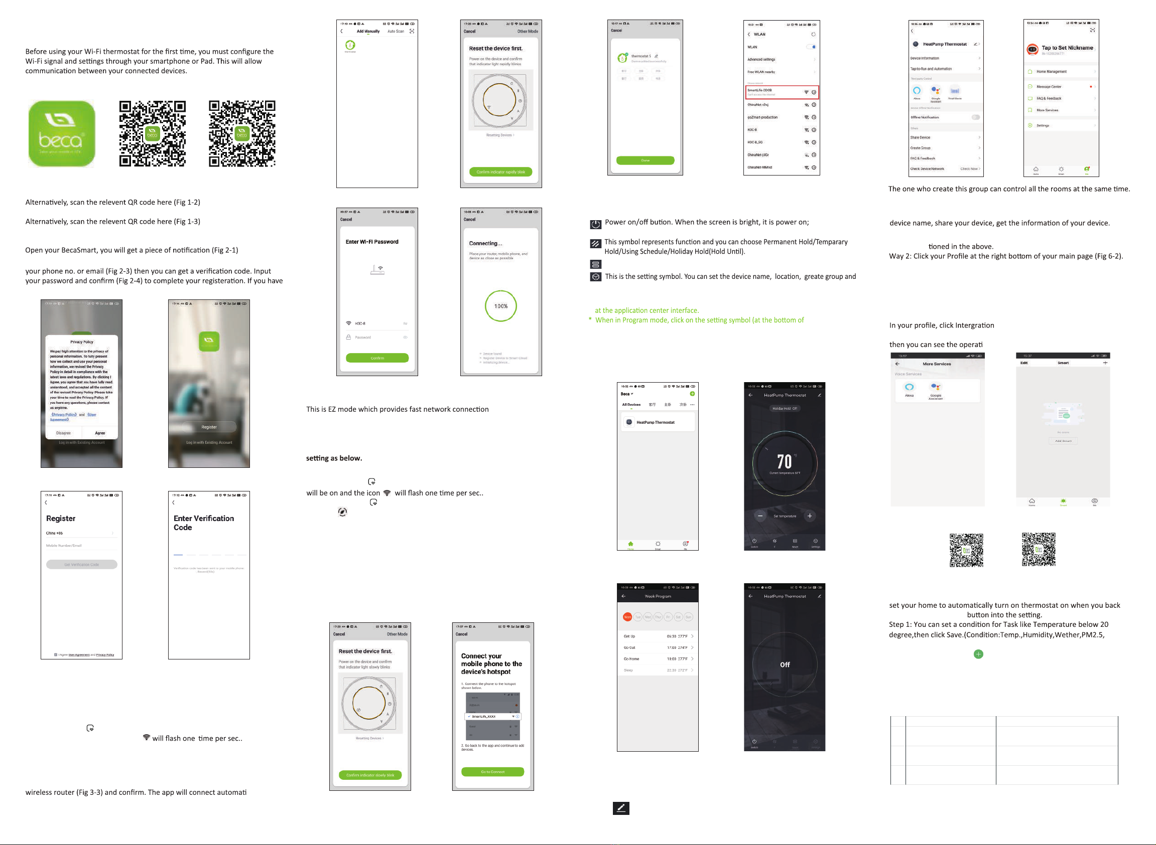
ABOUT WIFI
WI-FI CONNECTION
Step 1 Download your APP (Fig 1-1)
Fig 1-1 Fig 1-2 IOS Fig 1-3 Android
For IOS devices, search for My BecaSmart in Apple Store and download.
For Android devices, search for My BecaSmart in Google play and download.
Step 2 Register your account
Click Allow to go into your page of register (Fig 2-2). Press register and enter
account, please log in.
Fig 2-1 Fig 2-2
Fig 2-3 Fig 2-4
Step 3 Connect your Wi-Fi signal
On your thermostat
Press and hold the arrow for eight (8) seconds.
The backlight will be on and the icon
Then, go back to the home page of your app
Press the
+
on the upper right corner of the page (see Fig 3-1) to add
your device. Click Confirm indicator rapidly blink (Fig 3-2) then select
your network and back to your app to enter the password of your
cally
(Fig 3-4). This may typically take up to 5~90 seconds to complete.
Your room name could be edited when the device is connected (Fig 4-4).
Fig 3-1 Fig 3-2
Fig 3-3 Fig 3-4
between your app and
your device. If your router doesn’t support it or your wifi signal is weak or you
can not connect by EZ mode, press the AP Mode on the upper right corner in
Fig 3-2.
If you have connected your thermostat successfully, please ignore the AP
On your thermostat
Press and hold the arrow for eight (8) seconds. The backlight
Press and hold the arrow for eight (8) seconds agian.
The icon will flash one time every (3) seconds.
Then, go back to the home page of your app
Click Confirm indicator slowly blink (Fig 4-1) then select your network and back
to your app to enter the password of your wireless router (Fig 3-3) and confirm.
The app will go into the page in Fig 4-2.
Press Connect now to select the wifi signal Smartlife-CE4A of your
thermostat (Fig 4-3).
Go back to your app and click Connect now then the app will connect
automatically (Fig 3-4)
This may typically take up to 5~90 seconds to complete.
Your room name could be edited when the device is connected (Fig 4-4).
Fig 4-1 Fig 4-2
Fig 4-3 Fig 4-4
PROGRAMMING YOUR THERMOSTAT
*
the page) to be taken to the schedule page. (See Fig 5-2)
* You can set the temperature for a week and different periods of the day.
(Fig 5-3 )
* Once your schedule has been set, click SAVE and the app will send the
programming to your thermostat and confirm the schedule has been saved.
Fig 5-1 Fig 5-2
Fig 5-3 Fig 5-4
Fig 6-1 Fig 6-2
How to share your device with your family member?
Way 1: Men
You can see the sharing account you have sent and the device you have
shared in this sharing page.
Except create the group, in this menu page, you can also modify your
Note
Select Device Sharing then add the account you want to share.
How to connect your device to Amazon Echo or Google Home?
into the using page. Press Use Now >
(Fig 7-1) for your Amazon Echo or Google Home or Tmall Genie
on steps.
You don’t need to do anything if you are the one shared.
You can add as many as rooms you want.
What is your Smart Scene and How to use it?
Customize your own personal scenes to suit your needs. For example,
home (Fig 7-2).Press
+
Air Quality,Sunrise/Sunset,Device)
Step 2: Add a task. Press to Select Device (Power,Set Temp,Lock
Mode) to act, then Save.If you want to delete the scene,you can press
Delete in the end.
SIMPLE EXCEPTION HANDLING
SERVICE
Your thermostat carries an 24 months warranty from date
of purchase. Service outwith the warranty period may
incur a charge. More detail please contact with us directly.
NOTE: The room sound could be turned on/off in PROFILE-SETTING-
SOUND. The sound is matched with the default of your system .
Fig 7-1 Fig 7-2
when the screen is dark, it is power off.
When your room is established successfully, it will display on the home screen
(Fig 5-1).Click the line into begining programming our thermostat.
Press - + to adjust the temperature. The adjusted temperature will be displayed
Mode, press it you can choose Auto/ Cool/Heat/Emer/Off.
so on.
How to create a group?
Press then click Create Group (Fig 6-1).
Select all the rooms you want and confirm.
Scan the following QR code to see user guide of Amazon Echo, Google Home.
Amazon Echo Google Home
No. Phenomenons Handling
1 Power is on but without display. * Check if the terminals between LCD panel and
Power Unit Box is loosen.
2 Without output but display works. * Use a new LCD panel or new Power Unit Box to
replace the old one.
3 Room Temp. Is a little different from
the actual.
* Do temperature calibration in item 1 of high
senior options

This equipment has been tested and found to comply with the limits for a Class B digital
device, pursuant to part 15 of the FCC Rules. These limits are designed to provide reasonable
protection against harmful interference in a residential installation. This equipment generates,
uses and can radiate radio frequency energy and, if not installed and used in accordance with
the instructions, may cause harmful interference to radio communications. However, there is
no guarantee that interference will not occur in a particular installation. If this equipment does
cause harmful interference to radio or television reception, which can be determined by turning
the equipment off and on, the user is encouraged to tryto correct the interference by one or
more of the following measures:
•Reorient or relocate the receiving antenna.
•Increase the separation between the equipment and receiver.
•Connect the equipment into an outlet on a circuit different from that to which
the receiver is connected.
•Consult the dealer or an experienced radio/TV technician for help.
Caution:Any changes or modifications to this device not explicitly approved by
manufacturer could void your authority to operate this equipment.
This device complies with part 15 of the FCC Rules. Operation is subject to the following two
conditions: (1) This device may not cause harmful interference, and (2) this device must accept
any interference received, including interference that may cause undesired operation.
The device has been evaluated to meet general RF exposure requirement.
FCC Statement
Other BECA Thermostat manuals


Popular Thermostat manuals by other brands

Lennox
Lennox iComfort M30 user guide

DELTA DORE
DELTA DORE Tybox 1137 Installation and user guide

Neptronic
Neptronic TFL24 Specification & installation instructions

Honeywell Home
Honeywell Home T4 Pro user manual

Danfoss
Danfoss DEVI DEVIreg 530 installation guide

Honeywell
Honeywell EConnect TL9160AR operating manual


Aube Technologies
Aube Technologies TH135-01 Installation and user guide

Lux Products
Lux Products LuxPro SMART TEMP P521Ua Installation and operating instructions

Honeywell Home
Honeywell Home T10 Pro RedLINK manual

Aprilaire
Aprilaire 8910W Safety & installation instructions

Honeywell
Honeywell TH9421C1004 installation guide

Aube Technologies
Aube Technologies TH135-01 Installation and user guide