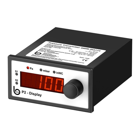
Beck 990 Series User manual

1 - 8
990
Kompakte Luft-/Differenzdruck
Messumformer Display P2
mit einstellbarem Druckmessbereich
Compact Air/Differential
Pressure Transmitter Display P2
with adjustable pressure range
SICHERHEIT & PRODUKTHAFTUNG
SAFETY & LIABILITY
Das in dieser Anleitung aufgeführte Produkt darf nur von ausgebildeten Fachleuten montiert, angeschlossen und
in Betrieb genommen werden. Die geltenden Sicherheitsbestimmungen, Verwendungszweck und technischen
Daten sind unbedingt einzuhalten. Gemäß diesen Bestimmungen müssen Anlagen spannungsfrei geschaltet und
vor unbeabsichtigtem Wiedereinschalten gesichert werden. Beschädigte Produkte dürfen nicht verwendet
werden. Das Produkt darf nicht für U.S. FDA kontrollierte Anwendungsbereiche verwendet werden.
Für Schäden,
die durch unsachgemäße Verwendung entstehen, z.B. Demontage der Platine, Ab-/ Aufstecken der
Displaybaugruppe oder Beschädigung des Gehäuses, wird keine Haftung übernommen.
The product mentioned in this manual can only be installed, connected and put into operation by trained
professionals. The existing safety regulations, the intended use and the technical data must be strictly observed.
According to these regulations, plants must be zero
-potential and secured against inadvertently restart. Damaged
products cannot be used. The product cannot be used for U.S. FDA controlled application areas. For damage
caused by improper use no liability is assumed. Disassembling the electronic board / display module or damage
the housing will void the warranty.
ELEKTRISCHER ANSCHLUSS
ELECTRICAL CONNECTION
GEFAHR DURCH STROMSCHLAG: Bei Arbeiten an der Elektrik darf keine Spannung anliegen. Durchführung
der Arbeiten entsprechend den gesetzlichen Vorschriften vornehmen. Der Differenzdruck-Messumformer ist zum
Einbau in Betriebsmitteln vorgesehen. Bei Nutzung der Schaltausgänge mit Niederspannung, muss der
elektrische Anschluss gemäß der Niederspannungsrichtlinie erfolgen. Passende Klingenbreite für
Klemmschrauben verwenden.
DANGER OF ELECTRIC SHOCK: No voltage must be applied if you work on electric systems. Carry out the
service work according to legal rules. The Differential Pressure Transducer is provided for installation in
equipment. If using the switching outputs with low voltage, the electrical connection must be compliance in
accordance with the Low Voltage Directive. Use a matching screwdriver for the clamping screws.
REINIGUNG, WARTUNG, ENTSORGUNG
CLEANING, MAINTENANCE, DISPOSAL
Reinigung mit Mikrofasertuch. Das Gerät ist wartungsfrei. Die meisten unserer Produkte enthalten wertvolle Rohstoffe und sollten
deshalb einem geordneten Recycling zugeführt werden. Bitte beachten Sie die geltenden nationalen Vorschriften, Gesetze und
Regelungen.
Cleaning with microfiber cloth. The device is maintenance-free. Most of our products may contain valuable materials that should
be recycled and not disposed of as domestic waste. Please observe the applicable relevant regulations and laws.

2 - 8
TECHNISCHE DATEN
TECHNICAL DATA
990M 990A
Versorgungsspannung Supply Voltage 18...30 VAC / DC
Ausgangssignal Output signal 0...10 V oder / or 4...20 mA
Bürde für Ausgang
4…20 mA Working resistance for output
4…20 mA 20...500 Ω
Bürde für Ausgang
0…10 V Working resistance for output
0…10 V ≥1 kΩ(≤10 mA)
Max. Stromaufnahme Max. current draw <190 mA <250 mA
Druckmedium Pressure medium Luft und nicht aggressive Gase / Air and non aggressive gases
Messverfahren Measuring process Piezoresistiver Drucksensor / Piezoresistive pressure transducer
Linearität
(inkl. Hysterese und
Reproduzierbarkeit)
Linearity
(incl. hysteresis and
repeatability) ≤±0,5% FS, min. ±1 Pa / ≤±0.5% FS, min. ±1 Pa
Unsicherheit
(Gesamtfehler ohne Langzeit-
und Temperatureinfluss)
Uncertainty
(Total Error Band w/o long-
term and temperature effects) ±1% FS, min. ±1 Pa
Langzeitstabilität Long-term stability ≤±1% FS, min. ±1 Pa n.r.
Betriebstemperatur Operating temperature 0...50°C (32…122°F)
Lagertemperatur Storage temperature -10...70°C (14…158°F)
Feuchte Humidity 0...95% rel., nicht kondensierend / 0...95% rel., non condensing
Einstellbare Ansprechzeit des
Ausgangssignals Response time switchable 0,1 s bis 20 s / 0.1 s to 20 s
Prozessanschluss Pressure connection 4 mm und 6 mm Schlauchstutzen
4 mm and 6 mm hose connection
Elektrischer Anschluss Electrical connection Schraubklemmen für Drähte und Litzen bis 1,5 mm²
Screw connector for cable and leads up to 1.5 mm2
Befestigung Mounting Schalttafeleinbau nach DIN IEC 61554
Panel mounting in accordance with DIN IEC 61554
Gehäuseabmessungen Casing dimensions 143 x 96 x 48 mm
Gewicht Weight ca. 230 gr / appr. 230 g
Schutzart nach EN60529 Protection to EN 60529 IP 20
Normen / Konformität Standards / Conformity EMV Richtlinie / EMC Directive
RoHS Richtlinie / RoHS Directive
Niederspannungsrichtlinie / Low Voltage Directive
Genauigkeitsangaben nach EN 60770 bezogen auf die Druckmessung bei 23°C
Accuracy specifications according to EN 60770 based on the pressure measurement at 23°C

3 - 8
BESTELLMATRIX 990
X
.3
X
3
X
1
X
ORDER MATRIX
I
II
III
IV
V
VI
Bestell
-
Code
Order code
I
Nullpunktabgleich /
Offset calibration
Manuell / Manual M
Automatisch /
Automatic A
II
Druckmessbereich
/
Pressure range
0…25 Pa /
0…25 Pa (0…0,25 mbar / 0…0.25 mbar)nur als 990A erhältlich / only available as 990A 0
0…50 Pa /
0…50 Pa (0…0,5 mbar / 0…0.5 mbar)nur als 990A erhältlich / only available as 990A 1
0…100 Pa /
0…100 Pa (0…1,0 mbar / 0…1.0 mbar)2
0…250 Pa /
0…250 Pa (0…2,5 mbar / 0…2.5 mbar)3
0…500 Pa /
0…500 Pa (0…5,0 mbar / 0…5.0 mbar)4
0…1 kPa /
0…1 kPa (0…10 mbar /
0…10 mbar)5
0…2,5 kPa /
0 …2.5 kPa (0…25 mbar /
0…25 mbar)6
0…5 kPa /
0…5 kPa (0…50 mbar /
0…50 mbar)7
0…10 kPa /
0…10 kPa (0…100 mbar /
0…100 mbar)8
0…25 kPa /
0…25 kPa (0…250 mbar /
0…250 mbar)9
0…50 kPa /
0…50 kPa (0…500 mbar /
0…500 mbar)A
0…100 kPa /
0…100 kPa (0…1,0 bar / 0…1.0 bar)B
0…250 kPa /
0…250 kPa (0…2,5 bar / 0…2.5 bar)F
I
II
Druckeinheit
/
Pressure unit
Pascal (kPa), mbar, inWC 3
I
V
Ausgangssignal
/
Output signal
0 …10 V / 4 …20 mA, mit 2 Schaltausgängen / 0 …10 V / 4 …20 mA, with 2 switching outputs 1
4 …20 mA / 0 …10 V, mit 2 Schaltausgängen / 4 …20 mA / 0 …10 V, with 2 switching outputs 3
V
Anzeige
/
Display
LED- Anzeige, 4-stellig, rot / LED display, 4 digits, red 1
V
I
Elektrischer Anschluss
/
Electrical connection
Schraubklemmen 24VAC/VDC / screw terminals for 24VAC/VDC 4
Steckernetzteil 100 bis 240VAC (50 bis 60Hz) / wall power supply for 100 to 240VAC (50 to 60Hz) 5
DRUCKMESSBEREICHE
PRESSURE RANGES
Baureihe
Model
Druckbereich
Pressure range
Überdruck
Sicherheit
Over pressure
safety
Berstdruck
Burst
pressure
Zusätzliche Unsicherheit durch
Temperatur [% FS/10K]
Additional uncertainty with
temperature [% FS/10K]
990M 990A
990A.303 0 …25 Pa / 0 …25 Pa 60 kPa 100 kPa - ± 1,0 / ± 1.0
990A.313 0 …50 Pa / 0 …50 Pa 60 kPa 100 kPa - ± 0,7 / ± 0.7
990x.323 0 …100 Pa / 0 …100 Pa 60 kPa 100 kPa ± 1,0 / ± 1.0 ± 0,5 / ± 0.5
990x.333 0 …250 Pa / 0 …250 Pa 60 kPa 100 kPa ± 0,7 / ± 0.7 ± 0,3 / ± 0.3
990x.343 0 …500 Pa / 0 …500 Pa 75 kPa 125 kPa ± 0,5 / ± 0.5 n.r.
990x.353 0 …1 kPa / 0 …1 kPa 75 kPa 125 kPa ± 0,3 / ± 0.3 n.r.
990x.363 0 …2,5 kPa / 0 …2.5 kPa 85 kPa 135 kPa ± 0,3 / ± 0.3 n.r.
990x.373 0 …5 kPa / 0 …5 kPa 85 kPa 135 kPa ± 0,3 / ± 0.3 n.r.
990x.383 0 …10 kPa / 0 …10 kPa 85 kPa 135 kPa ± 0,3
/
± 0.3
n.r.
990x.393 0 …25 kPa / 0 …25 kPa 135 kPa 275 kPa ± 0,3 /± 0.3 n.r.
990x.3A3
0 …50 kPa / 0 …50 kPa 200 kPa 400 kPa ± 0,3
/
± 0.3
n.r.
990x.3B3 0 …100 kPa / 0 …100 kPa 200 kPa 400 kPa ± 0,3 /± 0.3 n.r.
990x.3F3
0 …250 kPa / 0 …250 kPa 400 kPa 800 kPa ± 0,3
/
± 0.3
n.r.
Weitere Druckmessbereiche auf Anfrage / Further pressure ranges upon request

4 - 8
MONTAGE / ABMESSUNG & ANSCHLUSSPLAN
INSTALLATION / DIMENSIONS & CONNECTION PLAN
Der Differenzdruck-Messumformer kann in beliebiger Einbaulage montiert
werden. Durch den Nullpunktabgleich wird der Lagefehler eliminiert.
The differential pressure transducer can be mounted in any position. The
zero compensation eliminates errors due to positioning.
Elektrische Anlagen dürfen nur durch autorisierte Elektrofachkräfte errichtet,
erweitert, geändert und in Stand gehalten werden.
Electrical equipment may only be installed, added to, changed or maintained
by authorized electricians.
Rückseite / Back
Anschluss Steckernetzteil
Connection wall power supply
Anschlussklemme / Connection screw terminals
1 …10
WICHTIG: Schläuche dürfen beim Anschließen und Verlegen nicht geknickt oder beschädigt werden. Undichte Schläuche und
Schlauchanschlüsse verursachen Störungen am Gerät oder liefern falsche Messergebnisse.
Ø innen = < 3,5 / 5,5 mm für optimale Klemmung. Ab 25 kPa Schlauchklemme verwenden.
P1 = Überdruckmessung
P2 = Unterdruckmessung
P1 & P2 = Differenzdruckmessung
IMPORTANT: Pressure hoses may not be bent or damaged during installation. Leaking hoses and hose connections will cause
errors on the device or inaccurate measurements.
Inner Ø = < 3.5 / 5.5 mm for optimal clamping. From 25 kPa hose clamps must be used.
P1 = positive pressure measurement
P2 = negative pressure measurement
P1 & P2 = Differential pressure measurement
S1 (
≤50VAC)
S2 (
≤250VAC)

5 - 8
Funktionseinstellungen des Druckmessumformers Display P2
Anzeige
Hauptmenü*
Bemerkung
Drehknopf Anzeige
Parameter Einheit Information / Beschreibung
Drücken (1x)
Drehen
(Beispiel)
250 Typ: 990M.333114
Pa Aktueller Druckwert
Druckbereich: 0 …250 Pa
Analogausgang: 0 …10 V
(Menü Start)
2x Drücken= Zurück zum Menüpunkt ohne die Einstellung
zu ändern
Option 1
-3
Pa Nullpunkt anzeigen
-125 …125
Pa Nullpunkt verschieben (
±
50% vom Druckbereich)
0
Pa Nullpunkt speichern (Anzeige blinkt zur Bestätigung)
OFFS 1
Option 2**
(Ab F.2.02) >5 s -3
Pa Offsetwert anzeigen
0
Pa Offsetkorrektur wird durchgeführt
(Anzeige blinkt zur Bestätigung)
SP1 2
25
Pa Schaltpunkt 1 anzeigen
1 …250
Pa Schaltpunkt 1 einstellen
50
Pa Schaltpunkt 1 speichern (Anzeige blinkt zur Bestätigung)
HYS1 2
2
Pa Hysterese für SP1 anzeigen
1 …250
Pa Hysterese für SP1 einstellen
5
Pa Hysterese für SP1 speichern (Anzeige blinkt zur Bestätigung)
SP2 2
75
Pa Schaltpunkt 2 anzeigen
1 …250
Pa Schaltpunkt 2 einstellen
100
Pa Schaltpunkt 2 speichern (Anzeige blinkt zur Bestätigung)
HYS2 2
10
Pa Hysterese für SP2 anzeigen
1 …250
Pa Hysterese für SP2 einstellen
5
Pa Hysterese für SP2 speichern (Anzeige blinkt zur Bestätigung)
OuA 2
0-10
V Art des Analogausgangssignales (V oder mA) anzeigen
0-10 / 4-20
V / mA Umschaltung zwischen 0-10 V / 4-20 mA
4-20
mA Einstellung speichern (Anzeige blinkt zur Bestätigung)
AEP 2
250
Pa Druckbereichsende (AEP) anzeigen
125 …250
Pa AEP einstellen (50% …100% vom Druckbereich)
200
Pa AEP speichern (Anzeige blinkt zur Bestätigung)
dAA 2
0.1
s Ansprechzeit des Analogausgangs anzeigen
0.1 …20.0
s Ansprechzeit einstellen
1.0
s Ansprechzeit speichern (Anzeige blinkt zur Bestätigung)

6 - 8
Func 2
lin
- Analogausgang anzeigen (linear / radiziert)
lin / rAd
- Umschaltung zwischen linear / radiziert
rAd
- Einstellung speichern (Anzeige blinkt zur Bestätigung)
CAL
2
0.52
- k-Faktor anzeigen
0.01 …1.00
- k-Faktor einstellen
CAL / rho 0.80
- Einstellung speichern (Anzeige blinkt zur Bestätigung)
1.00
- Dichte (rho) anzeigen
rho 0.80 …1.50
- rho einstellen
1.25
- Einstellung speichern (Anzeige blinkt zur Bestätigung)
HI 267
Pa Maximalen Druck anzeigen (Spitzenwert)
Lo 0
Pa Minimalen Druck anzeigen (Spitzenwert)
dISP 2
10
% Helligkeit des Displays (LED) anzeigen
10 …100
% Helligkeit einstellen
50
% Helligkeit speichern (Anzeige blinkt zur Bestätigung)
=> Im Programmiermodus immer auf 100%, nach Hardware-
Reset geht die Helligkeit auf den eingestellten Wert zurück
Uni 2
1
Pa Druckeinheit anzeigen
1 …3
Pa /
mbar /
inWC
Druckeinheit einstellen (LED 1…2...3 auf der Front)
LED1 Pa; LED2 mbar; LED3 inWC
2
mbar Druckeinheit speichern (Anzeige blinkt zur Bestätigung)
OP-h 48
h Betriebsstunden anzeigen
Fir F.2.01
Pa Softwarestand Firmware anzeigen
PArA P. 21
Pa Parameternummer anzeigen
PASS 3
32
- Passwort anzeigen
0 …99
- Passwort ändern
77
- Passwort speichern (Anzeige blinkt zur Bestätigung)
=> Aktiv nach Hardware-Reset
End 2.00
mbar Menüende / zurück zur Druckanzeige
Hinweis: Die Tabelle zeigt die maximale Konfiguration an. Die Verfügbarkeit der Menüpunkte hängt von der bestellten Konfiguration ab
* Hauptmenüpunkte werden über das Drehen des Drehknopfes erreicht
** Diese Menüfunktion ist nur ab Firmware F.2.02 verfügbar
1
Menüpunkt ist nur bei 990M auswählbar
- Option 1: Nullpunktverschiebung
- Option 2: Offsetabgleich (Nullpunktkorrektur) nur im drucklosen Zustand
2
Funktionen sind gesperrt - ausgenommen wenn Passwort "0" oder "71 (Masterpasswort)" ist
3
Masterpasswort =
71
ermöglicht den Zugriff auf das Gerät bei verlorenen Passwort

7 - 8
Function settings of the pressure gauge Display P2
Display
Main menu*
Remark
Rotary button Setting
parameter Unit Information / description
Press (1x)
Turn
(Example)
250 Type: 990M.333114
Pa Current pressure value
Pressure range: 0 …250 Pa
Analogue output: 0 …10 V
(Menü Start)
Press 2x= Back to the menu item without changing the
setting
Option 1
-3
Pa Zero point (offset) is displayed
-125 …125
Pa Set zero point (±50% of pressure range)
0
Pa Save zero point (Display flashes for confirmation)
OFFS 1
Option 2**
(From F.2.02) >5 s -3
Pa Offset value is displayed
0
Pa Offset correction is performed (Display flashes for confirmation)
SP1 2
25
Pa Switching point 1 is displayed
1 …250
Pa Set switching point 1
50
Pa Save switching point 1 (Display flashes for confirmation)
HYS1 2
2
Pa Hysteresis for SP1 is displayed
1 …250
Pa Set hysteresis for SP1
5
Pa Save hysteresis for SP1 (Display flashes for confirmation)
SP2 2
75
Pa Switching point 2 is displayed
1 …250
Pa Set switching point 2
100
Pa Save switching point 2 (Display flashes for confirmation)
HYS2 2
10
Pa Hysteresis for SP2 is displayed
1 …250
Pa Set hysteresis for SP2
5
Pa Save hysteresis for SP2 (Display flashes for confirmation)
OuA 2
0-10
V The type of analogue output signal (V or mA) is displayed
0-10 / 4-20
V / mA Set output signal to 0-10V / 4-20 mA
4-20
mA Save setting (Display flashes for confirmation)
AEP 2
250
Pa End of pressure range (AEP) is displayed
125 …250
Pa Set AEP (50%...100% of the pressure range)
200
Pa Save AEP (Display flashes for confirmation)
dAA 2
0.1
s Response time of the analogue output is displayed
0.1 …20.0
s Set response time
1.0
s Save response time (Display flashes for confirmation)

8 - 8
Func 2
lin
- Analogue output is displayed (linear / square root)
lin / rAd
- Set output signal to linear / square root
rAd
- Save setting (Display flashes for confirmation)
CAL
2
0.52
- k-factor is displayed
0.01 …1.00
- Set k-factor
CAL / rho 0.80
- Save setting (Display flashes for confirmation)
1.00
- Density rho of the medium is displayed
rho 0.80 …1.50
- Set rho
1.25
- Save setting (Display flashes for confirmation)
HI 267
Pa Maximum pressure (peak value) is displayed
Lo 0
Pa Minimum pressure (peak value) is displayed
dISP 2
10
% Brightness of LED is displayed
10 …100
% Set brightness
50
% Save setting (Display flashes for confirmation)
=> In programming mode always set to 100%, if a hardware
reset is performed, the brightness always goes to the set value
Uni 2
1
Pa Pressure unit is displayed
1 …3
Pa /
mbar /
inWC
Set pressure unit (LED 1…2...3 on the front)
LED1 Pa; LED2 mbar; LED3 inWC
2
mbar Save pressure unit (Display flashes for confirmation)
OP-h 48
h Operating hours is displayed
Fir F.2.01
Pa Version of firmware is displayed
PArA P. 21
Pa Parameter number is displayed
PASS 3
32
- Password is displayed
0 …99
- Set password
77
- Save password (Display flashes for confirmation)
=> Active after hardware reset
End 2.00
mbar Menu end / back to the pressure display
Note: The table shows the maximum configuration. Availability of menu items depends on the ordered configuration
* The main menu points are reached by turning the rotary button
** This function is only available from the Firmware F.2.02
1
Menu item can only be selected at 990M
- Option 1: Adjust the zero shift
- Option 2: Adjust the zero offset only in unpressurized condition
2
Functions are blocked - except if the password is "0" or "71 (Master password)"
3
Master password=
71
enables access to the instrument if the password is lost
8.930.276-1
990
manual german_english
8.930.
276
-
1
Technische Änderungen vorbehalten. /
Technical data subject to change without prior notice.
Copyright©
2018 Beck GmbH
This manual suits for next models
26
Table of contents
Other Beck Measuring Instrument manuals
