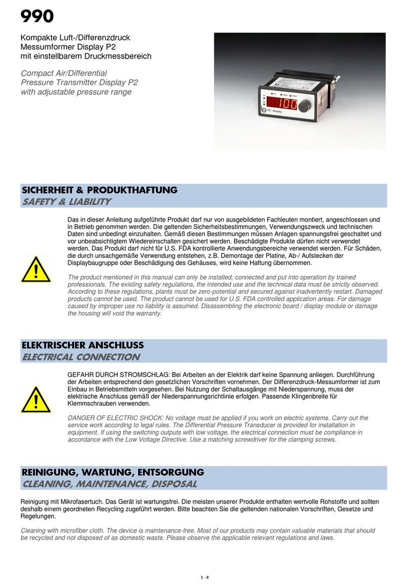
Beck Display P2 Specification sheet

Operating and
Installation Manual
Differential pressure gauge Display P2 for air
with 7 segment LED display,
and 2 switching outputs, for
• Building automation, air-conditioning and
clean-room technology
• Val e and damper control
• Filter, fan and blower monitoring
• Air flow control
Technical data
Pressure measurement ranges
Supply voltage
Type 990M with manual
zeroing
Type 990A with automatic
zeroing
Optional wall power supply
Output signal
Working resistance for output
4 ... 20mA
Power consumption
Pressure medium
Linearity and hysteresis error
Operating temperature
Storage temperature
Long-term stability, typical
16 ... 32VDC
18 ... 30VAC
22 ... 30VDC/AC
100 ... 240VAC(In)/24VDC(Out)
(50 ... 60Hz)
0 ... 10V and 4 ... 20mA
20 ... 480
Ω
< 100mA for DC
< 250mA for AC
Air and non-agressive gases
≤
±
1% of FS
0 ... 50°C
- 10 ... 70°C
≤
±
0.5% to
±
2.5% of FS/year,
Dependent on pressure range
Repeatability
Position dependence
Humidity
Response time, switchable
Process connection
Electrical connection
Attachment
Display
Instrument dimensions
Weight
IP rating after EN 60529
Standards / Conformity
≤
±
0.2% of FS
≤
±
0.02% of FS/g
0 ... 95% rel.,
non condensing
0.0 - 20.0s
4mm + 6mm tube connections
Screw terminals for wires and
braided wire up to 1.5mm²
Control panel
Red 7 segment LED display,
4-figure
143mm x 96mm x 48mm
230g
IP20
EN60770, EN61326
2002/95/EC (RoHS)
Type Pa mbar inWC Safe +ve pressure Burst pressure Temperature error
990A.303 0 ... 25 0.25 0.10 20 kPa 40 kPa
≤
±
5 % of FS
990A.313 0 .... 50 0.5 0.20 20 kPa 40 kPa
≤
±
5 % of FS
990x.323 0 ... 100 1.0 0.40 20 kPa 40 kPa
≤
±
5 % of FS
990x.333 0 ... 250 2.5 1.00 20 kPa 40 kPa
≤
±
5 % of FS
990x.343 0 ... 500 5.0 2.00 20 kPa 40 kPa
≤
±
2,5 % of FS
990x.353 0 ... 1 kPa 10 4.00 20 kPa 40 kPa
≤
±
1 % of FS
990x.363 0 ... 2.5 kPa 25 10.05 40 kPa 70 kPa
≤
±
1 % of FS
990x.373 0 ... 5 kPa 50 20.10 60 kPa 120 kPa
≤
±
1 % of FS
990x.383 0 ... 10 kPa 100 40.20 60 kPa 120 kPa
≤
±
1 % of FS
990x.393 0 ... 25 kPa 250 100.50 300 kPa 500 kPa
≤
±
1 % of FS
990x.3A3 0 ... 50 kPa 500 200.10 300 kPa 500 kPa
≤
±
1 % of FS
990x.3B3 0 ... 100 kPa 1,000 402.00 1.2 MPa 2 MPa
≤
±
1 % of FS
990x.3F3 0 ... 250 kPa 2,500 1,004.75 1.2 MPa 2 MPa
≤
±
1 % of FS

ELECTRICAL CONNECTION AND CONTROL PANEL DIMENSIONS
WARNING! Electrical systems must only be set-up, expanded, changed or updated by authorised electricians
or electrical techicians. Ne er work on electrical systems, if you are not qualified to do so.
When working on the electrical system, it must be at zero olts.
SWITC ING OUTPUT
The differential pressure gauge has two adjustable relay outputs in addition to the analogue output signal
at the terminals 5 ... 10 with a maximum switching capability of 250VAC/5A.
FASTENING & TUBE CONNECTION
N.B.: When connecting and routing tubes ensure they are not kinked or damaged.
Leaking tubes and tube connections cause instrument faults or result in
incorrect measurements.
Tube internal diameter = 3.5 / 5.5mm for optimum clamping. Use tube clamps from 25kPa.
P1 = Positi e pressure measurement
P2 = Vacuum measurement
P1 & P2 = Differential pressure measurement
SAFETY & PRODUCT LIABILITY
The product to which this manual refers must only be installed, connected and commissioned by trained specialists.
The rele ant safety conditions, intended use and technical data must be adhered to without fail. According to these conditions,
systems must be switched to a zero- olts condition and be secured to pre ent unintentional switching back on.
Damaged products must not be used. The product must not be used for US FDA controlled application fields.
No liability is accepted for damage arising from improper use.
DISPOSAL
The crossed out garbage can on this product indicates that at the end of its ser ice life, the product must be
disposed of separately from household waste. In future, please take all electrical and electronic products
to a suitably equipped municipal collection point for their reuse / recyling.

Function settings of the pressure gauge Display P2
Display
Main menu**
Remark
Rotary but-
ton
Press
Turn
Display
Rotary but-
ton
Press
Turn
Display
Sub-menu Unit Information / description
Example
250
Type: 990M.333114
Pressure range: 0 ... 250 Pa
Analogue output: 0 - 10 V
Pa Current pressure alue
OFFS
1
-3
-124 ... 125
0
Pa
Pa
Pa
Zero point (offset) is displayed
Adjust zero point
Sa e zero point (display flashes for confirmation)
SP1
3
25
1 ... 250
50
Pa
Pa
Pa
Switching point is displayed
Adjust switching point
Sa e switching point (display flashes for confirmation)
YS1
3
2
1 ... 250
5
Pa
Pa
Pa
Hysteresis is displayed for SP1
Adjust hysteresis for SP1
Sa e hysteresis for SP1
(Display flashes for confirmation)
SP2
3
75
1 ... 250
100
Pa
Pa
Pa
Switching point is displayed
Adjust switching point
Sa e switching point (display flashes for confirmation)
YS2
3
10
1 ... 250
5
Pa
Pa
Pa
Hysteresis is displayed for SP2
Adjust hysteresis for SP2
Sa e hysteresis for SP2 (display flashes for confirmation)
OuA
3
0-10
0-10 / 4-20
4-20
V
V / mA
mA
Display of the type of analogue output V or mA
Switching between 0-10V / 4-20 mA
Sa e setting (display flashes for confirmation)
AEP 3
250
50 .. 250
200
Pa
Pa
Pa
Display of the working end point (pressure range end)
Adjust AEP
Sa e AEP (display flashes for confirmation)
dAA 3
0,01
0.00 ... 20.00
0.10
s
s
s
Display damping time of the analogue output
Set the damping time
Sa e the damping time
(Display flashes for confirmation)

Func
2
lin
lin/sqrt
sqrt
-
-
-
Display analogue output function
Changeo er between linear / square root
Sa e setting (display flashes for confirmation)
=> Function is enabled by customer order
Default: linear
2
CAL
CAL / rho
rho
0.52
0.01 ... 1.00
0.80
-
-
-
Display Cal-factor
Adjust Cal-factor
Sa e setting (display flashes for confirmation)
2
1.00
0.08 ... 1.50
1.25
-
-
-
Display density rho of the medium
Set rho
Sa e setting (display flashes for confirmation)
I 250 Pa Display maximum applied pressure
Lo 0 Pa Display minimum applied pressure
dISP
10
10 ... 100
50
%
%
%
Display (LED) brightness
Adjust brightness
Sa e brightness (display flashes for confirmation)
=>In programming mode always set to 100%, once pro-
gramming mode is finished, the brightness always goes
smoothly to the set alue
Uni
3
1
1 ... 3
2
Pa
Pa/
mbar/
inWC
mbar
Display the selected unit of pressure
Set the pressure unit (LED 1...2...3) on the front
LED1 Pa; LED2 mbar; LED3 inWC
Sa e pressure unit (display flashes for confirmation)
LED2 illuminates for mbar
=>Pressure units are specified by the customer
OP-h 48 h Operating hours display
Fir F.1.02 Display ersion of firmware
PArA P.021 Display software ersion parameter
PASS
32
32
0 ... 99
77
-
-
-
-
Password (blocks function settings³ in the instrument,
except if the password is "0")
Do not change the password
Set/alter the password
Sa e password (display flashes for confirmation)
Master password = 71
=>enables access to the instrument if the password
is lost
End 2.00 mbar Menu end / back to the pressure display
** The main menu points are reached by turning the rotary knob
1 Not applicable for the 990A type as the version with automatic zeroing.
2 Only available if the optional function "square root" has been ordered.
3 Blocked function setting - except if the password is "0" or "071" (master password).
Beck GmbH
Pressure control technology
Postfach 11 31
D-71140 Steinenbronn
Phone +49 (71 57) 52 87-0
Fax +49 (71 57) 52 87-83
e-mail [email protected]
http://www.druckschalter.de
Other Beck Measuring Instrument manuals
Popular Measuring Instrument manuals by other brands
Omron
Omron K6CM series Startup guide
Blancett
Blancett QUIKSERT Operation & installation manual
Elster
Elster 6 Series Wiring instructions
Omicron Lab
Omicron Lab Bode 100 Detailed Functional & Calibration Check

Sigma Metalytics
Sigma Metalytics Precious Metal Verifier INVESTOR 3012 manual

DENT Instruments
DENT Instruments PowerScout HD Series Operator's guide
