Becker FEP-1000-CH User manual

FEP-1000/1500-CH
Series Flexible Element Pilot
Instruction Manual (Rev. C)
Baker Hughes Data Classification : Public

ii | Baker Hughes © 2021 Baker Hughes Company. All rights reserved.
THESE INSTRUCTIONS PROVIDE THE CUSTOMER/OPERATOR WITH IMPORTANT
PROJECT-SPECIFIC REFERENCE INFORMATION IN ADDITION TO THE CUSTOMER/
OPERATOR’S NORMAL OPERATION AND MAINTENANCE PROCEDURES. SINCE
OPERATION AND MAINTENANCE PHILOSOPHIES VARY, BAKER HUGHES (ITS
SUBSIDIARIES AND AFFILIATES) DOES NOT ATTEMPT TO DICTATE SPECIFIC
PROCEDURES, BUT TO PROVIDE BASIC LIMITATIONS AND REQUIREMENTS CREATED
BY THE TYPE OF EQUIPMENT PROVIDED.
THESE INSTRUCTIONS ASSUME THAT OPERATORS ALREADY HAVE A GENERAL
UNDERSTANDING OF THE REQUIREMENTS FOR SAFE OPERATION OF MECHANICAL
AND ELECTRICAL EQUIPMENT IN POTENTIALLY HAZARDOUS ENVIRONMENTS.
THEREFORE, THESE INSTRUCTIONS SHOULD BE INTERPRETED AND APPLIED IN
CONJUNCTION WITH THE SAFETY RULES AND REGULATIONS APPLICABLE AT THE
SITE AND THE PARTICULAR REQUIREMENTS FOR OPERATION OF OTHER EQUIPMENT
AT THE SITE.
THESE INSTRUCTIONS DO NOT PURPORT TO COVER ALL DETAILS OR VARIATIONS IN
EQUIPMENT NOR TO PROVIDE FOR EVERY POSSIBLE CONTINGENCY TO BE MET IN
CONNECTION WITH INSTALLATION, OPERATION OR MAINTENANCE. SHOULD FURTHER
INFORMATION BE DESIRED OR SHOULD PARTICULAR PROBLEMS ARISE WHICH ARE
NOT COVERED SUFFICIENTLY FOR THE CUSTOMER/OPERATOR’S PURPOSES THE
MATTER SHOULD BE REFERRED TO BAKER HUGHES.
THE RIGHTS, OBLIGATIONS AND LIABILITIES OF BAKER HUGHES AND THE CUSTOMER/
OPERATORARE STRICTLYLIMITEDTOTHOSEEXPRESSLYPROVIDEDINTHECONTRACT
RELATING TO THE SUPPLY OF THE EQUIPMENT. NO ADDITIONAL REPRESENTATIONS
OR WARRANTIES BY BAKER HUGHES REGARDING THE EQUIPMENT OR ITS USE ARE
GIVEN OR IMPLIED BY THE ISSUE OF THESE INSTRUCTIONS.
THESE INSTRUCTIONS ARE FURNISHED TO THE CUSTOMER/OPERATOR SOLELY TO
ASSIST IN THE INSTALLATION, TESTING, OPERATION, AND/OR MAINTENANCE OF THE
EQUIPMENT DESCRIBED. THIS DOCUMENT SHALL NOT BE REPRODUCED IN WHOLE
OR IN PART WITHOUT THE WRITTEN APPROVAL OF BAKER HUGHES.

Becker FEP-1000/1500-CH Series Pilot Instruction Manual | 1
© 2021 Baker Hughes Company. All rights reserved.
Table of Contents
Page
Introduction ..........................................................................................................................1
Description...................................................................................................................1
Scope of Manual..........................................................................................................1
Model Number Explanation .........................................................................................1
Technical Assistance....................................................................................................1
Technical Information..........................................................................................................2
Advantages of the Combination Chamber FEP-CH Pilot............................................2
Technical Specifications...............................................................................................2
Materials of Construction.............................................................................................2
Applications .................................................................................................................2
Ordering Information...........................................................................................................3
FEP-CH Stock Numbers and Spring Ranges..............................................................3
Accessories..........................................................................................................................4
FSP Series Setpoint Change Pump ............................................................................4
RSM Series Remote Setpoint Module.........................................................................4
REM Remote Setpoint Module....................................................................................4
Setpoint Change Indicator ...........................................................................................4
NBV Series No Bleed Valve ........................................................................................4
Principles of Operation .......................................................................................................5
Pressure Reducing Regulator Mode ...........................................................................5
Backpressure Regulator Mode ....................................................................................5
Explanation of Droop ...................................................................................................7
Piping Schematics..........................................................................................................9-10
Downstream Pressure Control ....................................................................................9
Backpressure Control ................................................................................................10
Drawings........................................................................................................................11-12
FEP-1000/1500-CH Pilot Spring Chamber................................................................ 11
FEP-1000/1500-CH Sensing Chamber ..................................................................... 11
FEP-1000/1500-CH Body..........................................................................................12
FEP-1000/1500-CH Bottom Cartridge.......................................................................12
Assembly Procedures .................................................................................................13-19
List of Recommended Tools.............................................................................................20
Parts Silhouettes................................................................................................................20
Introduction
The Becker FEP-CH series single-acting pilot represents a
breakthrough in valve control technology for the natural gas
industry. Built to exacting specications, this easily maintained
unit offers highly accurate control characteristics over a wide
range of operating environments.
Description
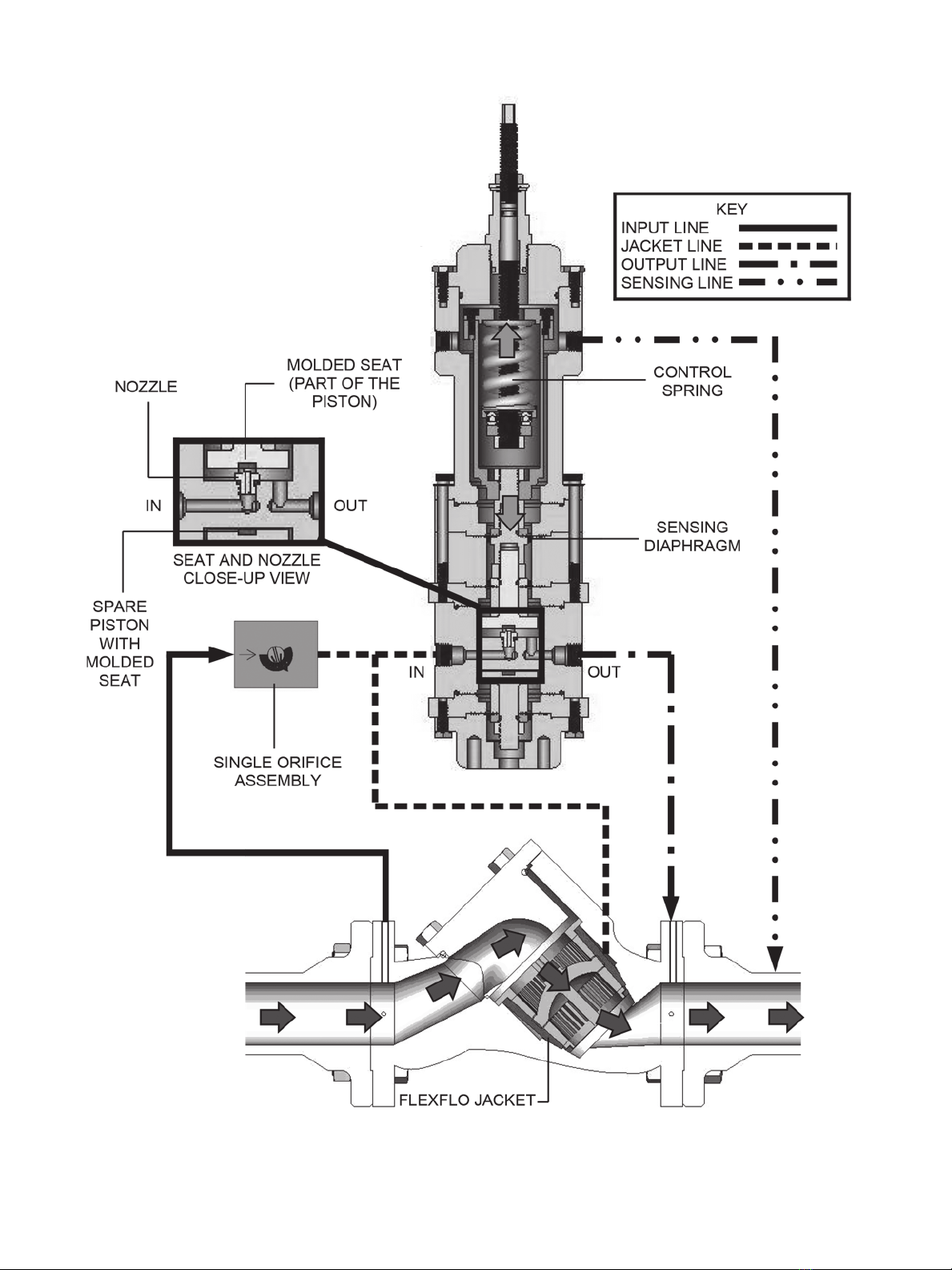
The Becker FEP-CH single-acting pilot provides pressure
control when used with a boot or diaphragm style regulator. The
FEP-CH measures downstream sensing pressure and positions
the control element of the regulator to maintain the desired
downstream pressure. The FEP-1000/1500-CH pilot may be
used for pressure control applications with setpoints ranging
from 550 psig to 1500 psig. The FEP-CH design pilot represents
our commitment to continually develop new products and update
existing ones to increase their performance while retaining
simple operation and low maintenance.
Scope of Manual
This manual provides information on the installation, operation,
adjustment, and maintenance of the Becker FEP-1000/1500-
CH single acting pilot. For information concerning valves and
accessories, refer to the instruction manuals provided with the
specic product.
Model Number Explanation
The FEP-CH pilot is available in two different models to cover
sensing pressures from 550 psig to 1500 psig. The number
expressed in the FEP model designation is the maximum
sensing pressure; for example, a FEP-1500-CH has a maximum
sensing pressure of 1500 psig.
To nd your FEP model number, refer to the stainless steel tag
attached to your pilot by the 7/16 hex head cap screws.
Note: Only those qualied through training or experience
should install, operate, or maintain Becker positioners.
If there are any questions concerning these instructions,
contact your Baker Hughes sales representative, sales
ofce, or manufacturer before proceeding.
Technical Assistance
Should you have any questions, you may contact your local
Baker Hughes sales representative or technical assistance
at e-mail address appearing on the back cover page of this
Manual.

2 | Baker Hughes © 2021 Baker Hughes Company. All rights reserved.
Technical Information
Advantages of the Combination Chamber
FEP-CH Pilot
1. Control spring surrounded by the natural gas media is
protected against corrosion caused by exposure to the
outside weatherconditions and condensation (specically
critical for vault installation).
2. The Sensing Pressure and the Control Spring forces in
the FEP-CH are combined in the same “CH” combined
chamber so that only the “small net force” is transmitted to
the FEP-CH Pilot Body. In all other brands, the forces have
a “sandwich” effect over the pilot body and the resulting
force is “crushing” pilots. This feature contributes for a much
higher sensitivity and smaller Lock-Up. See gure 1 below.
3. Larger measured variable chamber volume dampens
control pressure signal, helping to compensate for vibration
induced by poor location of sensing tap in area of ow
pulsation and turbulence.
4. Control springs can be replaced without disturbing any
diaphragms.
5. Springs are guided by the outside resulting in better
alignment and higher sensitivity.
6. Totally friction free design.
Table 2. Materials of Construction
External Parts Anodized 2024 Aluminum/316 SS Available
Internal Parts 316 Stainless Steel and 2024 Anodized
Aluminum
Springs Alloy Steel
Diaphragm Buna-N with nylon reinforcement
Seats and O-Rings Buna-N
Table 1. Technical Specications
Supply Gas Dry, Filtered (100 micron gas)
Maximum Flow Capacity See Cv Tables
Maximum Supply Pressure
Inlet
1480 psig (10204 kPa)
Maximum ΔP 1000 psig (6895 kPa)
Maximum Sensing Pressure 1500 psig (10342 kPa)
Maximum Discharge Pres-
sure Outlet
1300 psig (8963 kPa)
Maximum Bottom Chamber
(for remote loading)
1500 psig (10342 kPa)
Operative Ambient
Temperature Range
-20 to 160°F
-29 to 71°C
Approximate Weight 6 pounds (2.7 kg)
Setpoint Range 550 psig - 1500 psig
(3792 kPa - 10342 kPa)
Installation Orientation Vertical position recommended
Other Brands Becker FEP-CH
Figure 1. Schematic for the net force
Applications
• Primary Pressure Control
• Overpressure Protection (Monitor)
• Underpressure Protection (Standby)
• Relief Valve
• Backpressure Control
• Power Plant Type Applications
Compatible Regulators
• Redq Flexo™
• American Meters Axialow
• Fisher 399
• Mooney™ Flowgrid™

Becker FEP-1000/1500-CH Series Pilot Instruction Manual | 3
© 2021 Baker Hughes Company. All rights reserved.
Ordering Information
When ordering parts for the FEP-1000/1500-CH, there is
important information that needs to be specied. Using Table 3,
the correct spring number and color is chosen for your specic
control range. Tables 4, 5, and 6, give correct nozzle size, variable
orice, and repair kit ordering information for your application. In
all, when ordering, the customer should follow this format:
Ordering Example:
BPE Model FEP-1000-CH-NC (30-0039), Pressure Control Range
550-1000 psig (Yellow Spring , 25-1306), 1/8” Nozzle (25-1030),
“M” Orice Assembly (25-8162)
Table 4. FEP-1000/1500-CH Nozzle Information
Diameter Part No. Application
3/32” 25-1029 Gas
1/8” 25-1030 Liquid
FEP-CH Model Number Repair Kit Part #
FEP-1000-CH 30-9028
FEP-1500-CH 30-9028
FEP-1000-CH-NC 30-9028
FEP-1500-CH-NC 30-9028
Table 5. FEP-1000/1500-CH Orice Part Information
Identica-
tion Stamp
Variable Ori-
ce Assembly
Orice Only
Part Number
Standard
(no stamp)
(25-1559) (25-1040)
“M” (25-8162) (25-8075)
“L” (25-8163) (25-8076)
Table 6. FEP-1000/1500-CH Repair Kit Part Information
FEP-CH Model No. Control Range
(psig/kPa)
Spring Color
(Part Number)
Setpoint Change per
Revolution of Set-
point Screw (psig/
kPa)
Setpoint Range
Discrete Remote
Control (SM-1100)
Setpoint Range
Analog (4-20 mA)
Remote Control
(SM-1000)
FEP-1000-CH
FEP-1000-CH-NC(1) 550 – 1000 psig
3792
– 6895 kPa
Yellow
(25-1306)
143 psig
990 kPa
700 psig
4826 kPa
700 psig
4826 kPa
FEP-1500-CH
FEP-1500-CH-NC(1)
800 – 1300 psig
5516
– 8964 kPa
Grey
(25-1562)
227 psig
1565 kPa
850 psig
5860 kPa
850 psig
5860 kPa
900 – 1500 psig
6205 – 10342 kPa
Violet
(25-8073)
276 psig
1903 kPa
950 psig
6550 kPa
950 psig
6550 kPa
(1) NC = Normally Closed, for backpressure control.
Table 3. FEP-1000/1500-CH Control Spring and Setpoint Information

4 | Baker Hughes © 2021 Baker Hughes Company. All rights reserved.
Accessories
The following accessories are available to enhance the operation
or provide additional features to your FEP-CH series single-
acting pilot control system. For additional information regarding a
specic accessory, contact Baker Hughes.
FSP Series Setpoint Change Pump:
Provides a simple and accurate method of applying false signal
pressure during initial adjustment of the FEP pilot. The pump can
provide a false signal pressure of 10%-20% in excess of working
pipeline pressure which eliminates the need for nitrogen bottles
or electronic calibration devices.
RSM Series Remote Setpoint Module:
The Remote Setpoint Module provides remote adjustment of
FEP-CH Pilot setpoint via an electrical input signal. All Remote
Setpoint Motors are equipped with internal limit switches to
prevent over-travel of setpoint. 4-20 mA feedback of Remote
Setpoint Module is standard. All Becker RSM Series remote
Setpoint Modules are rated Explosion Proof Class1, Div 1 for use
in hazardous locations. Standard RSM input signals are:
Digital Input:
24 VDC and 120 VAC
Analog Input:
4-20 mA command signal/24 VDC supply power and
4-20 mA command signal/120 VAC supply power
REM Series Remote Setpoint Module:
The REM model requires additional diaphragm and spacer. It can
be used as pneumatic remote set point or differential controller.
Setpoint Change Indicator:
Provides a visual indication of the setpoint change from a known
reference setpoint. This device reduces the time required to vary
setpoint occasionally such as “winter” and “summer” setpoints for
high and low pipeline system demand.
Pneumatic Remote Loading:
Provides ability to change setpoint by remote pneumatic
pressure.
Also, can be used to control differential pressure.
Input Pressure Here

Becker FEP-1000/1500-CH Series Pilot Instruction Manual | 5
© 2021 Baker Hughes Company. All rights reserved.
Principles of Operation
Pressure Reducing Regulator Mode (Figure 2):
In order to understand how the FEP-1000/1500-CH pilot works,
refer to the diagram on page 6: when the outlet line pressure
is above the set pressure of the pilot, the net force on the
sensing diaphragm (represented by the “down” arrow in the
spring chamber) is down. This brings the seat to the nozzle,
and the pilot remains closed. The closed pilot seals the Flexo
jacket from the downstream line, allowing the jacket pressure to
equalize with the inlet pressure. This balanced force closes the
Flexo.
When outlet line pressure falls below the set pressure of the
pilot, the spring force takes over and the net force on the
sensing diaphragm is now up (represented by the “up” arrow in
the spring chamber). This force moves the seat away from the
nozzle and the pilot opens, allowing gas in the jacket to ow out
to the downstream line. When pressure outside the regulator
jacket drops, the ow through the Flexo increases. In time,
this increased ow raises the downstream pressure enough
as to create a downward net force on the sensing diaphragm.
Eventually, the downward force on the sensing diaphragm
begins to close the nozzle and pressure builds again outside the
Flexo jacket. This pressure now restricts the ow through the
Flexo and the downstream pressure begins to decrease. When
the downstream pressure decreases enough to equal the set
pressure of the pilot, the pilot remains at an equilibrium condition
and the jacket and inlet pressures are equal.
Backpressure Regulator Mode (Figure 3):
In this mode, the main block of the pilot is ipped upside-down,
such that the nozzle faces down (refer to Figure 3). When the
inlet line pressure is below the set pressure of the pilot, the net
force on the sensing diaphragm (represented by the “up” arrow in
the spring chamber) is up. This brings the seat to the nozzle, and
the pilot remains closed. The closed pilot seals the Flexo jacket
from the downstream line allowing the jacket pressure to equalize
with the inlet pressure. This balanced force closes the Flexo.
When inlet line pressure rises above the set pressure of the
pilot, the net force on the sensing diaphragm is now down
(represented by the “down” arrow in the spring chamber). This
force moves the seat away from the nozzle and the pilot opens,
allowing gas in the jacket to ow out to the downstream line.
When pressure outside the regulator jacket drops, the ow
through the Flexo increases. In time, this increased ow lowers
the upstream pressure enough to let the spring force create
an upward net force on the sensing diaphragm. Eventually, the
upward force on the sensing diaphragm begins to close the
nozzle and pressure builds again outside the Flexo jacket.
This pressure now restricts the ow through the Flexo and
the upstream pressure begins to increase. When the upstream
pressure increases enough to equal the set pressure of the pilot,
the pilot remains at an equilibrium condition and the jacket and
inlet pressures are equal.
IN
NOZZLE
OUT
MOLDED SEAT
Figure 3. Block turned upside down for back pressure applications.

6 | Baker Hughes © 2021 Baker Hughes Company. All rights reserved.
Figure 2. FEP-1000-CH Principles of Operation
Pressure Reducing Regulator Mode.

Becker FEP-1000/1500-CH Series Pilot Instruction Manual | 7
© 2021 Baker Hughes Company. All rights reserved.
Explanation of Droop:
Lock-up or droop depends on the amount of gas owing through
the supply orice. The internal nozzle has to be large enough to
unload the supply orice. In steady-state the supply ow will be
equal to the discharge ow. In order to understand Tables 7, 8, 9,
10 and 11, a sample derivation and calculation is given below:
Given:
P1 = pressure at inlet, P2 = pressure at outlet,
AN = area of the nozzle, K = spring constant,
DN = diameter of the nozzle, AD= area of the diaphragm
A simple force –balance equation in steady state shows:
(1) FD= FS+ FN
The force from the nozzle (FN), is simply the difference in the
pressure from the inlet and outlet multiplied by the area of the
nozzle:
(2) FN= (P1- P2) x AN = ΔP x AN
The force on the spring comes from the equation:
(3) FS= K x X
We can look at the case when the pilot is in steady-state and the
nozzle and orice are wide open. The maximum distance that
this is achieved is when the seat is DN/4 inches from the nozzle
opening. Therefore we know the maximum deection of the
spring is:
(4) X = DN/4
SPRING
DIAPHRAGM
FD= DIAPHRAGM
FORCE
FS= SPRING
FORCE
FN= NOZZLE
FORCE
Since we know the given spring constant, K, for a yellow or gray
spring: (5) FS= K x (DN/4)
We are interested in the pressure droop, but (1) only solves for
the total droop force. So now we introduce equation (6) in order
to nd the pressure droop (PD):
(6) FD= PDx AD
So now our nal equation for the maximum droop will be:
(7) PDMAX = (ΔP x AN+ K x X)/ AD
An important fact to note is that (4) happens only at the extreme
case that the nozzle is wide open, when the full lift force is acting
on the seat. Of course the pilot can also be in steady-state when
the seat is at an intermediate position from the nozzle (not fully
closed, but not quite at X = DN/4 either). Therefore we must
multiply the ratio of the orice and nozzle ow factors (CV) by the
full lift distance (DN/4) in order to nd the correct spring deection,
X for different intermediate seat positions.
(8) X (FOR INTERMEDIATE POSITIONS) =
(CV ORIFICE/CV NOZZLE) x (DN/4)

8 | Baker Hughes © 2021 Baker Hughes Company. All rights reserved.
Table 8. Control Spring Constants
Spring Type K
(lbf/in)
Yellow 2398
Grey 3794
Table 9. Orice Flow Factor vs. Oricce Opening #0-7
Orice Flow
Direct
Opening Number
01234567
“STD” Forward 0.003 0.004 0.009 0.026 0.042 0.071 0.099 0.122
Reverse 0.043 0.045 0.055 0.069 0.083 0.109 0.135 0.154
“M” Forward 0.043 0.046 0.063 0.090 0.135 0.173 0.212 0.250
Reverse 0.093 0.097 0.112 0.135 0.173 0.212 0.250 0.289
“L” Forward 0.043 0.062 0.173 0.327 0.462 0.577 0.635 0.674
Reverse 0.099 0.154 0.250 0.366 0.462 0.597 0.674 0.674
Table 7. Nozzle Diameter, Flow Factor (Cv), Nozzle Area, Diaphragm
Area
Nozzle
Diameter (in) CvAN(in2) AD(in2)
3/32” 0.404 0.007 0.836
1/8” 0.635 0.012 0.836
Table 10. Results For Sample Pressure Droop Calculations (Psig)(1)
Nozzle Diameter
(in) Spring Color ΔP (psig)
200 400 600 800 1000
3/32” Yellow 6.0 7.6 9.3 10.9 12.6
Grey 8.5 10.1 11.8 13.5 15.1
1/8” Yellow 6.6 9.5 12.5 15.4 18.3
Grey 8.7 11.7 14.6 17.6 20.5
Table 11. Results For Sample Pressure Droop Calculations (Bar)(1)
Nozzle Diameter
(in) Spring Color ΔP (psig)
13.8 27.6 41.4 55.2 68.9
3/32” Yellow 0.4 0.5 0.6 0.8 0.9
Grey 0.6 0.7 0.8 0.9 1.0
1/8” Yellow 0.5 0.7 0.9 1.1 1.3
Grey 0.6 0.8 1.0 1.2 1.4
Note: As you follow the calculations, take note of the highlighted
boxes shown in Tables 7, 8, 9, 10 and 11. The boxes illustrate the
values used in this sample calculation.
Sample Calculation For Droop:
Given:
A FEP-1000-CH gas application using a standard orice set on
#3 in the forward ow direction conguration.
Find:
The pressure droop for a ΔP of 800 psig.
Solution:
Because it is a gas application a 3/32 in. nozzle is used. From
Table 7, the CVof this nozzle is 0.404 and the nozzle area is
0.007 in2. Using the knowledge that the model is a FEP-1000-
CH tells us that it uses a yellow spring. From Table 8, the spring
constant of the yellow spring is 2398 lbf/in. From Table 9, the
CV for a standard orice set on #3 in the forward ow direction
is 0.026. Finally, the effective diaphragm area of the FEP
1000/1500 CH pilots is given from Table 7 as 0.836 in2. Using
the tables, we have found all the unknowns needed to solve for
pressure droop, equation (7):
ΔP = 800 psig
AN= 0.007 in2
K = 2398 lbf/in
X = (0.026/0.404) x (0.09375/4) = 0.0015 in.
AD= 0.836 in2

Becker FEP-1000/1500-CH Series Pilot Instruction Manual | 9
© 2021 Baker Hughes Company. All rights reserved.
Table 10 shows the results of the droop calculation (equation
7) for ΔP values of 200, 400, 600, 800, and 1000 psig. For
convenience, Table 11 shows the same results as Table 10 given
in units of bars. From this we can see that for ΔP = 800 psig (55.2
bars) the pressure droop we can expect is 10.9 psig (0.8 bars).
What Does It Mean?
“Droop” is important to know about because it represents the
increase in output pressure (P2) when the output is suddenly
closed. Using the model FEP-1000-CH in a gas application with
a ΔP = 800 psig as an example, we can see from Table 10 that if
the output is suddenly closed the pressure will increase 10.9 psig
(0.8 bars).
(1)MAKE CAREFUL NOTE THAT TABLES 10 AND 11 ARE
DONE FOR A SPECIFIC ORIFICE SETTING (#3). THESE
TABLES ARE NOT VALID IF THE ORIFICE YOU USE
IS DIFFERENT. IN OTHER WORDS, IF IN TABLE 9 YOU
PICKED A #5 ORIFICE, ALL NEW CALCUATIONS WOULD
APPEAR IN TABLES 10 AND 11.
Piping Schematics
Application #1
Downstream Pressure Control
Flexible Element Regulator (Grove Flexo 900TE shown)
FEP-1000/1500-CH
NORMALLY OPEN
DOWNSTREAM SENSING LINE
(1000 PSIG MAX FOR FEP-1000-CH,
1500 PSIG MAX FOR FEP-1500-CH)
NOTE: REFER TO CVDATA FOR FORWARD
AND REVERSE INSTALLATION
IN THE TECHNICAL DATA SECTION

10 | Baker Hughes © 2021 Baker Hughes Company. All rights reserved.
FEP-1000/1500-CH
NORMALLY CLOSED
UPSTREAM SENSING LINE
(1000 PSIG MAX FOR FEP-1000-CH,
1500 PSIG MAX FOR FEP-1500-CH)
Backpressure Control
Flexible Element Regulator (Grove Flexo 900TE shown)
Piping Schematics
Application #2

Becker FEP-1000/1500-CH Series Pilot Instruction Manual | 11
© 2021 Baker Hughes Company. All rights reserved.
FEP-1000/1500-CH Pilot Spring Chamber Assembly
FEP-1000/1500-CH Sensing Chamber Assembly
Key Part No. Description
1 30-7022 Adjusting Screw
2 98-2500 7/16-20” Jam Nut
3 30-7009 Seal Neck
4 95-2672 O-Ring - 108
5 95-2670 O-Ring - 115
6 95-2671 O-Ring - 141
7A 30-7007 Std. Tube Cap
7B 30-7026 Tube Cap Gray Spring
8A 25-1306 Yellow Spring
8B 25-1562 Gray Spring
9A 30-7006 Standard Bearing Case
9B 30-7027 Gray Spring Bearing Case
10 25-1062 Thrust Bearing
11 30-7001 Bearing Nut
12 98-3213 1/2-20” LH Jam Nut (316)
13 30-7003 Inner Tube
14 98-3231 1/4-20 x 3” SHCS (316 SS)
15 98-3181 7/16 FT Washer (SS)
16 30-7017 7/16 Thread Seal
17 98-3137 1/4-20” x 3/4” HHCS (SS)
18 98-3269 8-32 x 1/2” SHCS (Alloy)
19 30-7023 High Pressure Spring Cartridge
20 98-3227 .250 x .500” Washer (Fiberglass)
21 98-3229 1/4-20 x 1-1/2” SHCS (316 SS)
Key Part No. Description
22 30-7016 Adapter Block
23 95-2665 O-Ring - 145
24 98-3056 1/2-20 Jam Nut (316)
25 30-7015 Thread Extension
26 30-7014 Small Washer
27 95-2615 O-Ring - 012
28 30-7058 Top Spacer
29 30-7011 Conv. Diaphragm w/ Hole
30 30-7010 Small Piston
1
15
16
17
18
19
20
21
2
3
4
5
6
7A, 7B
8A, 8B
9A, 9B
10
11
12
13
14
22
23
24
25
26
27
30
29
28

12 | Baker Hughes © 2021 Baker Hughes Company. All rights reserved.
FEP-1000/1500-CH Body Assembly
FEP-1000/1500-CH Bottom Cartridge Assembly
Key Part No. Description
31 30-7078 Body Spacer
32 30-7011 Conv. Diaphragm W/Hole
33 30-7079 Piston w/Seat
34 95-2665 O-Ring - 145
35 98-3269 8-32 x 1/2” SHCS (Alloy)
36 30-7080 Piston Spacer
37 98-3056 1/2-20 Jam Nut (316)
38 30-7081 1/2-20 Special Nut
39 98-3285 1/4-20 x 3/4” SHCS (Alloy)
40 30-7077 Single Body
41A 25-1029 3/32” Nozzle
41B 25-1030 1/8” Nozzle
42 25-1023 Pilot Post
43 30-7014 Small Washer
Key Part No. Description
44 98-3137 1/4-20 x 3/4” HHCS (SS)
45 30-7082 Modied Bottom Cartridge
31
32
33
34
34
35
36
37
45
43
44
42
41A, 41B
40
39
38

Becker FEP-1000/1500-CH Series Pilot Instruction Manual | 13
© 2021 Baker Hughes Company. All rights reserved.
A
D
G
D
C
C
H
F
G
E
E
H
B
C
P1
P1
P2
P2
Assembly Procedures
The following pages outline the complete assembly procedure
for the FEP-1000/1500-CH. The complete assembly of the
entire pilot is shown step by step.
These procedures are given as a guide but it should be
noted that only those qualied through training or experience
should install, operate, or maintain the FEP pilot. If there are
any questions concerning these instructions, please contact
your Baker Hughes sales representative, sales ofce, or
manufacturer before proceeding.
Single Body Assembly
Step 1. Insert a –010 O-ring (A) into the groove of the 3/32
nozzle (B). Thread the nozzle(1) into the single body (C).
(1) 3/32 nozzles are for gas applications. For liquid operation,
use 1/8 nozzle instead.
Piston Assembly
Step 1. Insert –012 O-ring (D) into the grooves of each piston
(E).
Step 2. Attach two pilot posts (F) to one of the pistons using 2,
8-32 x 1/2” SHCS (G).
Step 3. Slide the assembly from step 2 through the single body
(C) and attach it to the other piston using 2 more 8-32 x 1/2”
SHCS (G).
Single Body Assembly
Complete Piston Assembly
Single Body O-Ring Assembly
Pilot Post - Piston Assembly
Body Spacer Assembly
Step 1. Insert a –145 O-ring (H) into each groove of the single
body (C).
Note: During assembly moisten all O-rings, threads,
thrust bearings and the recess in the spring seat with
a lightweight silicone grease. HOWEVER, care should
be taken to avoid applying grease to diaphragm sealing
surfaces, as this may compromise diaphragm sealing.

14 | Baker Hughes © 2021 Baker Hughes Company. All rights reserved.
Step 2. Slide a piston spacer (I) over each piston. The grooved
side of the piston spacer should be facing away from the
pistons as shown in Body Spacer Assembly Figure here below.
Step 3. Fasten each body spacer (J) to the single body using 6,
1/4-20 x 3/4 SHCS (K). Take careful note of the orientation of
the body spacers before fastening them to the single body (C).
Body Diaphragm Assembly
Step 1. Slide a diaphragm (L) over each piston taking into
account the diaphragm convolute orientation shown in Body
Diaphragm Assembly [Figure here below.]
Step 2. Slide a grooved small washer (M) over each piston
taking into account the direction of the washer grooves shown
in Body Diaphragm Assembly [Figure here below.]
Step 3. Finish by threading a 1/2-20 aluminum nut (N) onto the
top piston, and a 1/2-20 SS jam nut (O) onto the bottom piston.
Torque both nuts to 180-220 in.-lbs.
K
N (1/2-20 Aluminum)
O (1/2-20 SS)
K
C
Piston Spacer (I)
Side View Grooves Face
Up
Body Spacer (J)
Side View
Piston Spacer (I) Side
View
Grooves Face Down
Small Washer (M)
Side View
Grooves Face
Down
Diaphragm (L)
Side View Convolute
Up
Diaphragm (L)
Side View
Convolute Down
Body Spacer (J)
Side View
Body Spacer Assembly Body Diaphragm Assembly
Small Washer (M)
Side View
Grooves Face Up
P1
P2

Becker FEP-1000/1500-CH Series Pilot Instruction Manual | 15
© 2021 Baker Hughes Company. All rights reserved.
Centering the Diaphragms
Step 1. Rotate the diaphragm assembly counter-clockwise until
it stops. Mark the diaphragm and body spacer with a single line.
Step 2. Rotate the diaphragm assembly clockwise until it stops.
Mark the body spacer with an extension from the line already
on the diaphragm.
Step 3. Draw a line exactly between the two lines already
on the body spacer. Center the diaphragm by rotating the
diaphragm assembly counter-clockwise until the line that exists
on the diaphragm matches the new center line on the body
spacer.
Bottom Cap Assembly
Step 1. Turn the entire assembly upside down.
Step 2. Fasten the bottom cartridge (P) to the bottom body
spacer using 6, 1/4-20 x 3/4” HHCS (Q). Torque to 100-110
in.-lbs.
Diaphragm Centering
Bottom Cartridge Assembly
P1
Step 1
Step 2
Q
P
Step 3
P1
P1
P2
P2
P2
P2
P1

16 | Baker Hughes © 2021 Baker Hughes Company. All rights reserved.
Assembling the Diaphragm
1000-1500-CH Chamber Assemblies
1000/1500-CH Adapter Block Assembly
Insert – 145 O-ring (F) into the adapter block (G). Place the
adapter block (G) between the diaphragm assembly and spring
chamber (H).Slide the inner tube (I) through the spring chamber
(H). Attach the thread extension (E) to the inner tube (I) using
1/2-20 SS jam nut (J). Torque the jam nut (J) to 180-220 in.-lbs.
1000/1500-CH Bottom Spacer Assembly
Orient the bottom spacer (K) onto the top body assembly (L).
Place the adapter block assembly onto the bottom spacer (K).
Making sure not to twist the diaphragm (C), thread the small piston
(B) into the outside piston (M) by holding the spring chamber (H)
and rotating the inner tube (I) clockwise. The inner tube (I) is rotat-
ed with the same socket wrench used to hold the jam nut (J) in the
adapter block assembly. When the inner tube (I) cannot be rotated
any more, do not force it; this assembly should only be hand-tight.
Assembling the Diaphragm
Connecting the Two Pistons
1000/1500-CH Diaphragm Assembly
Slide – 012 O-ring (A) onto the small piston (B). Place the dia-
phragm with hole (C) onto the piston (B). Slide the small washer
(D) onto the piston (B). Attach the thread extension (E) onto the
small piston (B). Torque to 180-220 in.-lbs.

Becker FEP-1000/1500-CH Series Pilot Instruction Manual | 17
© 2021 Baker Hughes Company. All rights reserved.
1000/1500 Spring Chamber Assembly
Fasten the bottom spacer assembly to the top body assembly (L)
using six (6) berglass washers (N) and six (6) 1/4-20 x 3-inch
SHCS (O). Bolt the spring chamber (H) into the bottom spacer (K)
using six (6) berglass washers (N) and six (6) 1/4-20 x 1 1/2-inch
SHCS (P).
Bolting the Spring Chamber

18 | Baker Hughes © 2021 Baker Hughes Company. All rights reserved.
Adjusting Screw Assembly
Step 1. Press t the thrust bearing (AA) into the bearing case
(BB for a FEP-1000-CH and CC for a FEP-1500-CH).
Press Fit Thrust Bearing and Bearing Case
Adjusting Screw Assembly
Spring Concentricity Test
Insert Spring Assembly into Tube
Step 2. Slide a –108 O-ring (DD) onto the adjusting screw (EE).
Slide the thrust bearing assembly from step 1 onto the adjusting
screw with the bearing side down.
Step 3. Thread the aluminium bearing nut (FF) onto the
adjusting screw from the bottom. Leave room below the bearing
nut and thread a SS LH 1/2-20 jam nut (GG) below the bearing
nut. The bearing nut and jam nut should be tightened against
each other as shown in the Adjusting Screw Assembly Figure
here below. Cap Assembly
Step 1. Insert the nished adjusting screw assembly into the
spring chamber. Fasten the tube cap to the inner tube with 4
Alloy 8-32 x 1/2” SHCS (LL)
Step 2. Slide a –141 O-ring (MM) into the groove of the
cartridge cap (NN).
Step 3. Slide a –115 O-ring (OO) into the groove of the seal
neck (PP).
Step 4. Thread the seal neck into the cartridge cap.
Step 4. Place the tube cap (HH or II) and control spring (JJ)
onto the adjusting screw. Check the concentricity of the spring
by spinning the assembly. Make sure that the spring touches no
parts of the adjusting screw when spinning. If the spring does
touch any part of the screw, then replace the spring and repeat
the test. When spring satises this test, continue to the next
step.
CC
AA
DD
Side View
Side View of
Adjusting Screw
After Assembly
Bottom Surface of LH Jam
Nut (GG) is Flush with
Bottom of Adjusting Screw
(EE)
Tighten the Faces of the
Two Nuts (FF And GG)
Against Each Other
EE
FF
FF
GG
GG
BB
HH or II
Lubricate
Adjusting
Screw (EE)
LL
JJ
This manual suits for next models
3
Table of contents
Other Becker Industrial Equipment manuals
Popular Industrial Equipment manuals by other brands

ABB
ABB Relion REC615 manual

Digital Control
Digital Control TERATRAK R1 user manual

Grundfos
Grundfos MG Series Installation and operating instructions

Phoenix Contact
Phoenix Contact TC MOBILE I/O X300 AC manual

Allen-Bradley
Allen-Bradley 140G-N-TLH3 Installation

BOC Edwards
BOC Edwards A531-15-020 instruction manual