manuals.online logo
Brands
  1. Home
  2. •
  3. Brands
  4. •
  5. Becker
  6. •
  7. Industrial Equipment
  8. •
  9. Becker MILINE User manual

Becker MILINE User manual

Other Becker Industrial Equipment manuals

Becker Centronic SensorControl SC43 User manual

Becker

Becker Centronic SensorControl SC43 User manual

Becker SV 5.90 User manual

Becker

Becker SV 5.90 User manual

Becker FEP-1000-CH User manual

Becker

Becker FEP-1000-CH User manual

Becker dvt 3.140 User manual

Becker

Becker dvt 3.140 User manual

Becker SV 500 User manual

Becker

Becker SV 500 User manual

Popular Industrial Equipment manuals by other brands

ABB Unifix AD Instruction handbook

ABB

ABB Unifix AD Instruction handbook

Mark 7 Evolution user manual

Mark 7

Mark 7 Evolution user manual

Husky HyPET Original instructions

Husky

Husky HyPET Original instructions

bora PM-1800 user manual

bora

bora PM-1800 user manual

Grizzly T32428 owner's manual

Grizzly

Grizzly T32428 owner's manual

Siemens 8MF1 Series operating instructions

Siemens

Siemens 8MF1 Series operating instructions

ABB HT610965 Operation manual

ABB

ABB HT610965 Operation manual

ABB SafeLink Installation and operating instructions

ABB

ABB SafeLink Installation and operating instructions

Phoenix PHX-150 user guide

Phoenix

Phoenix PHX-150 user guide

ABB A165-L32 Operation manual

ABB

ABB A165-L32 Operation manual

ABB HT842936 Operation manual

ABB

ABB HT842936 Operation manual

Hermetica 10 Series user manual

Hermetica

Hermetica 10 Series user manual

HORNER OEE Solution manual

HORNER

HORNER OEE Solution manual

Hammerhead HG375 parts manual

Hammerhead

Hammerhead HG375 parts manual

SCHUNK VERO-S NSE-A3 138 Assembly and operating manual

SCHUNK

SCHUNK VERO-S NSE-A3 138 Assembly and operating manual

ABB HT566657 Operation manual

ABB

ABB HT566657 Operation manual

Webasto GSE CAN installation guide

Webasto

Webasto GSE CAN installation guide

ABB HT614003 Operation manual

ABB

ABB HT614003 Operation manual

manuals.online logo
manuals.online logoBrands
  • About & Mission
  • Contact us
  • Privacy Policy
  • Terms and Conditions

Copyright 2025 Manuals.Online. All Rights Reserved.

QUICK
START
GUIDE
V1.00
Acorn Regulatory Consultancy Services Limited
Knockmorris Cahir Co. Tipperary Ireland
Postcode: E21 R766
P012 4626 8456
F012 4626 8648
©2022 Becker Orthopedic Appliance Co.
All rights reserved.
Revision 11/01/22
Contour the upper bar and stirrup to the
desired shape.
Important: Do not mar or bend the stirrup
or upper bar where they attach to the
component (Figure 1). Best practice
recommends using a smooth jaw vise to hold
the bars by the component attachment points
during contouring.
Step 3
Correct the cast prior to fabrication. Insert the 9.5mm (3/8”) diameter alignment
axis, included with the MILINE Fabrication Tool Kit, through the negative cast at
the desired position of the ankle axis. Fill the mold with plaster and when cured,
remove the alignment axis from the positive model and modify.
Step 1
Step 2
Assemble the fabrication tool for unilateral or bilateral fabrication.
Attach the upright and stirrup to the MILINE fabrication tool using the
appropriate size adapter plate. Set the desired clearance to the positive model
using the included spacers. Note that each spacer gives 3mm (1/8”) of clearance.
For bilateral fabrication, insert both fab tool alignment bushings into the
alignment hole so that they telescope until the spacers touch the positive model.
For unilateral fabrication using a single
fabrication tool, install the shim on the
alignment bushing before inserting into the
alignment hole in the positive model.
Alignment Bushings
telescope and
maintain alignment
between components
while accomodating
size of positive model
Stack spacer(s) to set
clearance to clear
positive model 3mm
(1/8”) per spacer
Fabrication
tool maintains
alignment of stirrup
and upper bar
Upper Bar
Stirrup
Miline Fabrication Tool for Bilateral Conguration
Miline Fabrication Tool
Unilateral Conguration
Alignment
Bushing Shim
Adapter
Plate
After contouring, attach the upper bar(s) and
stirrup(s) to the fabrication tool and insert into the
positive model. Create the orthotic shell using the
desired fabrication technique. If thermoforming,
or fabricating open pocket laminated shells (with
the bars under the PVA bag), back-ll the bars with
plaster where they contact the positive model. If
integrating the bars into a laminated shell, remove
the adapter plate from the tool. Slide the inner PVA
bag over the mold and apply vacuum. Place the
adapter plate on the tool, over the PVA bag, and
attach with screws going through the bag.
Step 4
After fabricating, remove the bars from the fabrication tool and wipe clean using a rag
with solvent. DO NOT grind or blast the bars where they attach to the component.
Protect the areas shown in red using tape before nishing the bars (Figure 1).
Step 5
Final Assembly
a. The upper bar must be t to
the component. Use a le, or ne
sanding cone to t the upper bar. The
upper bar should require moderate
pressure from a vise, or arbor press
to seat the bar into the bar pocket.
Failure to properly t the upper bar
may result in screw loosening. Apply a
small drop of thread locking adhesive
to the bar attachment screws
(included) and tighten. Use a torque
wrench to torque the bar attachment
screws to the value shown in Table 1.
Step 6
(continued)
DO NOT bend or
mar bars inside
the red boxes
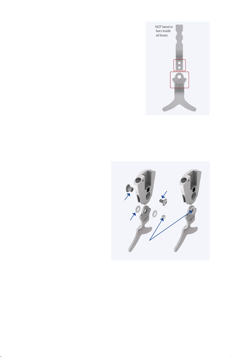
b. Install the MILINE stirrup with the selected thrust washers (included) to adjust
the mediolateral play of the component to the desired stability. Refer to Table 2
for thrust washers included by component size. After selecting the desired washer
thickness, use the thrust washer installation tool to hold the thrust washers in
alignment with the stirrup as it is pushed into the component body (Figure 2). When
the thrust washer installation tool is aligned with the pivot hole, install the pivot
bushing, pushing the thrust washer installation tool out of the pivot hole. Apply a
small drop of thread locking adhesive to the pivot screw and tighten. Use a torque
wrench to torque the pivot screw to the value shown in Table 1.
Figure 1
Figure 2
Pivot Screw
Pivot
Bushing
Thrust
Washer
Thrust Washer
Installation Tool
MILINE Screw Torque Specications
Spring Options for MILINE
Double Action & Dorsiexion
Assist Ankle Joints
Thrust Washers to Adjust ML Play (2-each included as shown)
Note: Different thicknesses of thrust washers may be combined.
13mm
16mm
20mm
Thrust Washers Included mm [in]
0.38 [.015] 0.50 [.020] 0.64 [.025] 0.76 [.030]
MILINE
Component Size 0.25 [.010]
13mm
16mm
20mm
T20
T25
T30
2.5
4
7
2.5
4
7
Pivot Screw
Torque (N-m)
MILINE
Component Size Drive Size (Torx) Bar Attachment
Screw Torque (N-m)
Table 3:
Table 2:
Table 1:
13mm
16mm
20mm
MILINE
Component Size
NB
Stiffness
Active ROM
Stiffness
Active ROM
Stiffness
Active ROM
Low
15°
Moderate
20°
Moderate/High
15°
Moderate
25°
Moderate
20°
Moderate/High
15°
High
12°
High
10°
Very High
10°
____
____
Very High
20°
Max Stiffness
15°
B1* B2 B3
No Booster Booster
* Spacer used in spring conguration B1