3
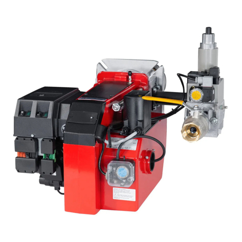
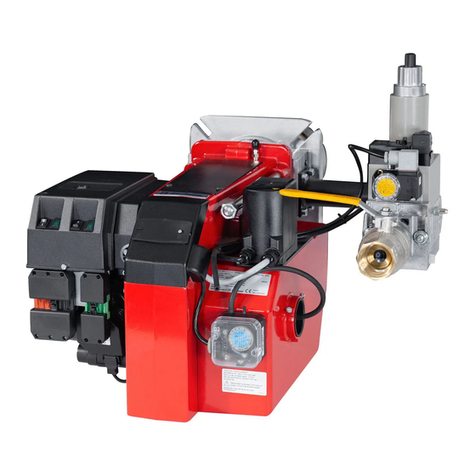
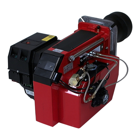
Bentone BG550/650
Contents
1. DESCRIPTION ______________________________________________________________________________________________________________________ 5
1.1 Warning __________________________________________________________________________________________________________________________ 5
2. DESCRIPTION ______________________________________________________________________________________________________________________ 6
2.1 2-Stage___________________________________________________________________________________________________________________________ 6
2.2 Modulating ______________________________________________________________________________________________________________________ 7
3. TECHNICAL DATA ________________________________________________________________________________________________________________ 8
3.1 Dimensions _____________________________________________________________________________________________________________________ 8
3.2 Output range___________________________________________________________________________________________________________________ 9
3.3 Working field _________________________________________________________________________________________________________________ 10
4. SKELETON DIAGRAMS_____________________________________________________________________________________________________ 11
4.1 2-stage or modulating burners ________________________________________________________________________________________ 11
5. MOUNTING OF THE BURNER__________________________________________________________________________________________ 12
5.1 Inspection of gas assembly _____________________________________________________________________________________________ 12
5.2 Adjustment of the position of the shrouded disc in the blast tube ________________________________________ 13
6. ELECTRIC EQUIPMENT ___________________________________________________________________________________________________ 14
6.1 Wiring diagram LGB22/LMG22/LME22 (BG550/BG650) 2-Stage _______________________________________ 14
6.2 Wiring diagram LMG22/LME22 (BG550/BG550LN/BG650) Modulating_______________________________ 15
6.3 Wiring diagram LMG22/LME22 (BG550/BG550LN/BG650) Modulating with R316 _______________ 16
6.4 List of components LMG22/LME22 (BG550/BG550LN/BG650)__________________________________________ 17
6.5 Function LGB/LMG22/LME22 _________________________________________________________________________________________ 18
6.6 Control diagnosis under fault conditions and lockout indication Gas burner control: LGB ... __ 19
6.7 Control diagnosis under fault conditions and lockout indication Gas burner control: LMG ...__ 21
6.8 Control program when disruption; disruption display Gas burner control: LME.... ________________ 23
6.9 Wiring diagram LFL1... (BG550/BG650) 2-Steg_________________________________________________________________ 25
6.10 Wiring diagram LFL1... (BG550/BG550LN/BG650) Modulating ___________________________________________ 26
6.11 Wiring diagram LFL1... (BG550/BG550LN/BG650) Modulating with R316 ___________________________ 27
6.12 Wiring diagram LFL1... (BG550/BG650) 2-stage _______________________________________________________________ 28
6.13 List of components LFL1... (BG550/BG650) _____________________________________________________________________ 29
6.14 Funktion LFL1..._____________________________________________________________________________________________________________ 30
6.15 Control programme under fault conditions and lockout indication LFL1....____________________________ 31
7. MEASURES AND CHECKS BEFORE START-UP ___________________________________________________________ 32
7.1 2-Stage or modulating burners________________________________________________________________________________________ 32
7.2 Inner assembly BG 550LN ______________________________________________________________________________________________ 34
8. DETERMINATION OF GAS VOLUME FOR THE INSTALLATION ___________________________________ 35
8.1 Example how to calculate the gas volume (natural gas) ______________________________________________________ 35
9. GAS SOLENOID VALVE MVD ____________________________________________________________________________________________ 36
10. OPERATION AND ASSEMBLY INSTRUCTIONS______________________________________________________________ 37
10.1 Double solenoid valve Type DMV-D.../11 Type DMV-DLE.../11____________________________________________ 37
11. Gas pressure regulator Type FRS ____________________________________________________________________________________ 41
12. MULTI-BLOC, MB-ZRDLE 405-420__________________________________________________________________________________ 44
12.1 Flow adjustment 2-stage design ______________________________________________________________________________________ 45
12.2 Adjustment of governor __________________________________________________________________________________________________ 45
12.3 Adjustment of start gas flow____________________________________________________________________________________________ 45
13. MULTI-BLOC, MB-VEF 412-425 B01 _______________________________________________________________________________ 46
13.1 Technical data________________________________________________________________________________________________________________ 47
13.2 Mounting instruction - impulse lines PL, PFoch PBr______________________________________________________________________________________________________________47
13.3 Adjustment possibilities __________________________________________________________________________________________________ 47


