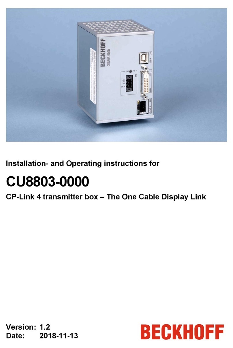
Beckhoff CU8803-000 Series User manual

Manual | EN
CU8803-000x
Transmitter box for CP-Link 4
2023-08-21 | Version: 2.0


Table of contents
CU8803-000x 3Version: 2.0
Table of contents
1 Notes on the documentation....................................................................................................................5
2 For your safety ..........................................................................................................................................6
2.1 Signal words......................................................................................................................................6
2.2 Intended use .....................................................................................................................................6
2.3 Fundamental safety instructions .......................................................................................................7
2.3.1 Special requirements (ATEX)............................................................................................. 7
2.3.2 Special requirements (IECEx)............................................................................................ 8
2.4 Operator's obligation to exercise diligence........................................................................................8
3 Product overview ......................................................................................................................................9
3.1 Structure............................................................................................................................................9
3.1.1 USB input .........................................................................................................................10
3.1.2 DVI input .......................................................................................................................... 10
3.1.3 CP-Link 4 output .............................................................................................................. 11
3.1.4 Power supply.................................................................................................................... 12
3.2 Name plate......................................................................................................................................13
4 Commissioning .......................................................................................................................................14
4.1 Transport and unpacking ................................................................................................................14
4.2 Control cabinet installation ..............................................................................................................15
4.3 Connect transmitter box ..................................................................................................................16
5 Decommissioning ...................................................................................................................................18
6 Maintenance ............................................................................................................................................20
7 Technical data .........................................................................................................................................21
8 Appendix..................................................................................................................................................22
8.1 Service and support ........................................................................................................................22
8.2 Approvals ........................................................................................................................................23

Table of contents
CU8803-000x4 Version: 2.0

Notes on the documentation
CU8803-000x 5Version: 2.0
1 Notes on the documentation
This description is only intended for the use of trained specialists in control and automation engineering who
are familiar with the applicable national standards.
The following instructions and explanations must be followed during installation and commissioning of the
components. The responsible staff must ensure that the application or use of the products described satisfy
all the requirements for safety, including all the relevant laws, regulations, guidelines and standards.
Disclaimer
The documentation has been prepared with care. The products described are, however, constantly under
development. For that reason the documentation is not in every case checked for consistency with
performance data, standards or other characteristics. In the event that it contains technical or editorial errors,
we retain the right to make alterations at any time and without warning. No claims for the modification of
products that have already been supplied may be made on the basis of the data, diagrams, and descriptions
in this documentation. All illustrations shown are only examples. The configurations depicted may deviate
from the standard.
Trademarks
Beckhoff®, TwinCAT®, TwinCAT/BSD®, TC/BSD ®, EtherCAT®, EtherCAT G®, EtherCAT G10®, EtherCAT P®,
Safety over EtherCAT®, TwinSAFE®, XFC®, XTS® and XPlanar® are registered and licensed trademarks of
Beckhoff Automation GmbH.
Other designations used in this publication may be trademarks whose use by third parties for their own
purposes could violate the rights of the owners.
Patents
The EtherCAT Technology is covered, including but not limited to the following patent applications and
patents: EP1590927, EP1789857, EP1456722, EP2137893, DE102015105702 and similar applications and
registrations in several other countries.
Copyright
© Beckhoff Automation GmbH & Co. KG. Publication of this document on websites other than ours is
prohibited. Offenders will be held liable for the payment of damages. All rights reserved in the event of the
grant of a patent, utility model or design.
Delivery state
All the components are supplied in particular hardware and software configurations appropriate for the
application. Changes to the hardware or software configuration are permitted, provided they are within the
specified limits for power consumption and power loss (please refer to the respective data sheet).
Currentness
Please check whether you are using the current and valid version of this document. The current version is
always available for download from the Beckhoff website. In case of doubt, contact Technical Support.
Delivery conditions
In addition, the general delivery conditions of the company Beckhoff Automation GmbH & Co. KG apply.

For your safety
CU8803-000x6 Version: 2.0
2 For your safety
The Safety chapter first explains the safety symbols used in the documentation and their meanings. They
contain fundamental safety instructions that are essential for the avoidance of personal injuries and damage
to property.
Exclusion of liability
Beckhoff shall not be liable in the event of non-compliance with this documentation and thus the use of the
devices outside the documented operating conditions.
2.1 Signal words
The signal words used in the documentation are classified below.
Warning of personal injuries
DANGER
Hazard with high risk of death or serious injury.
WARNING
Hazard with medium risk of death or serious injury.
CAUTION
There is a low-risk hazard that can result in minor injury.
Warning of property and environmental damage
NOTICE
There is a possibility of damage to the environment, equipment or data.
2.2 Intended use
The CP-Link4 transmitter box CU8803-000x is designed for DIN rail mounting in control cabinets of machine
and system engineering. It is used to operate a Control Panel CP29xx-0010, CP39xx-0010 or
CPX39xx-0010 at a distance of up to 100m from the industrial PC. The transmitter box can be used in
hazardous areas and is ATEX and IECEx certified.
The transmitter box is designed for a working environment that meets the IP20 protection rating. This
involves finger protection and protection against solid foreign objects up to 12.5mm. There is no protection
against water. Operation of the devices in wet and dusty environments is not permitted.
The specified limits for technical data must be adhered to.
The transmitter box can be used within the documented operating conditions.
Improper use
Do not use the transmitter box outside the documented operating conditions.

For your safety
CU8803-000x 7Version: 2.0
2.3 Fundamental safety instructions
The following safety instructions must be observed when handling the transmitter box.
Application conditions
• Do not use the transmitter box under extreme environmental conditions.
• Only use the transmitter box in hazardous areas if it is explicitly designed for this purpose.
• Never plug or unplug connectors during thunderstorms. There is a risk of electric shock.
• Provide protective grounding for the transmitter box.
Damage to property and impairment of functions
• Ensure that only trained specialists with a control and automation engineering background, operate the
PC to which the transmitter box is connected. Use by unauthorized persons can lead to damage to
property.
• Fuse the power supply line with max. 16A. The fuse serves to protect the supply line in the event of a
short circuit.
• In case of fire, extinguish the transmitter box with powder or nitrogen.
2.3.1 Special requirements (ATEX)
WARNING
Risk of explosion
Gases can be ignited in hazardous areas. Read and follow the safety instructions to avoid deflagration or
explosion.
The device must be installed in a suitable housing with IP54 protection rating according to EN 60079-15,
taking into account the environmental conditions in which the device will be used.
Precautions are to be taken to prevent the nominal voltage from being exceeded by transient disturbances in
excess of 119V.
Observe the permissible ambient temperature range of 0-55°C for the use of CU8803 in hazardous areas.
Secure the USB connector to the bracket with cable ties.
The device may only be used in an area with a maximum degree of pollution of 2 according to IEC 60664-7.

For your safety
CU8803-000x8 Version: 2.0
2.3.2 Special requirements (IECEx)
WARNING
Risk of explosion
Gases can be ignited in hazardous areas. Read and follow the safety instructions to avoid deflagration or
explosion.
The device must be installed in a suitable housing with IP54 protection rating according to EN 60079-15,
taking into account the environmental conditions in which the device will be used.
Precautions are to be taken to prevent the nominal voltage from being exceeded by transient disturbances in
excess of 119V.
Observe the permissible ambient temperature range of 0-55°C for the use of CU8803 in hazardous areas.
Secure the USB connector to the bracket with cable ties.
The device may only be used in an area with a maximum degree of pollution of 2 according to IEC 60664-7.
2.4 Operator's obligation to exercise diligence
The operator must ensure that
• the products are only used as intended (see chapter 2.2 Intended use [}6]).
• the products are only operated in sound condition and in working order.
• only sufficiently qualified and authorized personnel operate the PC to which the transmitter box is
connected.
• the personnel is instructed regularly about relevant occupational safety and environmental protection
aspects, and is familiar with the operating instructions and in particular the safety instructions contained
herein.
• the operating instructions are in good condition and complete, and always available for reference at the
location where the products are used.

Product overview
CU8803-000x 9Version: 2.0
3 Product overview
The CU8803-000x CP-Link4 transmitter box enables the control panel to be located up to 100m away from
the industrial PC. The transmitter box is located at a maximum distance of 1m from the industrial PC and
must be supplied with 24VDC. It transmits DVI, USB and the power supply to the control panel via a Cat.6A
cable (The One Cable Display Link).
The CU8803-0000 transmitter box is designed for connecting the Control Panels CP29xx-0010,
CP39xx-0010 and CPX39xx-0010 to a PC with a DVI port.
The CU8803-0001 transmitter box is designed for connecting the Control Panels CP29xx-0010 and
CP39xx-0010 to a C60xx PC or an ATX PC with DisplayPort.
3.1 Structure
The figure shows an example of a CU8803-0000 transmitter box.
1
4
6
7
2
5
3
Fig.1: Structure
Table1: Legend - CU8803 structure
No. Component Description
1 Power supply (X40) Power supply connection
2 FCC approval text FCC approvals for the United States of America and
Canada
3 Vendor Beckhoff Automation GmbH & Co. KG
4 Model Ending -0000: Device with DVI cable
Extension -0001: Device with DisplayPort cable
5 USB input (X10) Connection to the industrial PC
6 DVI input (X20) Connection to the industrial PC
7 CP-Link 4 output (X30) Transmission of DVI, USB and power supply to the
control panel

Product overview
CU8803-000x10 Version: 2.0
3.1.1 USB input
The transmitter box has a USB 2.0 input (X10) with socket type B. The transmitter box is connected to the
industrial PC via the USB input. The maximum cable length is 1 m.
2 1
4
3
X10
Fig.2: USB input pin numbering
Table2: USBinput pin assignment
Pin Assignment
1 Vbus
2 D -
3 D +
4 GND
3.1.2 DVI input
The transmitter box has a DVI input (X20). The transmitter box is connected to the industrial PC via the DVI
input. The maximum cable length is 1 m.
18
16
24
17
9
X20
Fig.3: DVI input pin numbering
Table3: DVI Extended interface pin assignment
Pin Assignment Pin Assignment Pin Assignment
1 TDMS Data 2 - 9 TDMS Data 1 - 17 TDMS Data 0 -
2 TDMS Data 2 + 10 TDMS Data 1 + 18 TDMS Data 0 +
3 TDMS Data 2/4 Shield 11 TDMS Data 1/3 Shield 19 TDMS Data 0/5 Shield
4 not used 12 not used 20 not used
5 not used 13 not used 21 not used
6 DDC Clock 14 + 5 V Power 22 TDMS Clock Shield
7 DDC Data 15 Ground (+ 5 V, Analog H/V
Sync)
23 TDMS Clock +
8 Analog Vertical Sync 16 Hot Plug Detect 24 TDMA Clock -

Product overview
CU8803-000x 11Version: 2.0
3.1.3 CP-Link 4 output
The transmitter box has a CP-Link 4 output (X30). The CP-Link 4 output connects the transmitter box to the
control panel, which acts as the operating element.
Using a Cat.6A cable, the transmitter box can transmit DVI, USB and the power supply to the control panel
(The One Cable Display Link). The control panel can thus be operated at a distance of up to 100m from the
transmitter box.
X30
1
8
P20
P30
Fig.4: CP-Link 4 pin numbering
Table4: CP-Link 4 pin assignment
Pin Signal
1 0 +
2 0 -
3 1 +
4 2 +
5 2 -
6 1 -
7 3 +
8 3 -
There are two LEDs at the CP-Link-4 output. The following table provides information about the meanings of
the LEDs.
Table5: CP-Link 4 LED meanings
LED Assignment Status Meaning
P20 Activity off
flashes yellow
no data transmission
DVI data is transferred
P30 Connection off
green illuminated
no connection to the control panel
Connection to the control panel established

Product overview
CU8803-000x12 Version: 2.0
3.1.4 Power supply
The transmitter box is supplied with a nominal input voltage of 24VDC. The power supply and the protective
earth of the device are connected via the 3-pin voltage socket (X40).
1
2
3
X40
Fig.5: Voltage socket pin numbering
Table6: Voltage socket pin assignment
Pin Signal Description
3 Protective earth
2 - Negative pole power supply 24V
1 + 24V 24V power supply, positive pole
The connector for the power supply is specified for 8A and can accept wire cross-sections up to 1.5 mm2
with ferrules without collars. When using ferrules with collars, the wire cross-section is reduced to 1mm2.
Use 1.5mm2 or 1mm2 for long supply lines to achieve a low voltage drop on the supply lines. At least 22V
should be present at the power supply plug of the transmitter box so that the transmitter box remains
switched on in the event of voltage fluctuations. The plug is included in the scope of delivery. You can obtain
a replacement plug from your Beckhoff Sales using the following ordering option:
• C9900-P944: Power supply connector for CU8xxx, 3-pin connector with spring-cage connection for the
external supply cables
The P10 LED is located above the interface. It provides information about the status of the power supply.
The LED indicates the following states:
• LED is off: no supply voltage
• LED lights up green: 24VDC applied
Fig.6: LED voltage socket

Product overview
CU8803-000x 13Version: 2.0
3.2 Name plate
The name plate provides information about the transmitter box equipment. The name plate shown here
serves only as an example of a device that may be used in a hazardous area.
1
2
3
4
5
6
78
9
xxxxxxxx
Fig.7: Name plate
Table7: Legend CU8803 name plate
No. Description
1 Manufacturer, including address
2 Model: The last four digits indicate the product variant
3 Serial number (BTN)
4 Revision
5 Year of production
6 Certification for use in hazardous areas
7 Certification for use in hazardous areas
8 Symbols
Note: Here are the symbols applicable to the device such as CE, EAC, UKCA, . The
approvals of your device can be found on the name plate and in chapter 9.2 Approvals [}23].
9 FCC approval

Commissioning
CU8803-000x14 Version: 2.0
4 Commissioning
In order to use the transmitter box, you must first commission it. The first step is to transport the device to is
operating location and unpack it. This is followed by mounting the device on the DIN rail and connecting the
data lines and the power supply.
4.1 Transport and unpacking
Note the specified transport and storage conditions (see Chapter 8 Technical data [}21]).
NOTICE
Hardware damage due to condensation
Unfavorable weather conditions during transport can cause damage to the device.
• Protect the device against moisture (condensation) during transport in cold weather or in case of
extreme temperature fluctuations.
• Do not put the device into operation until it has slowly adjusted to the room temperature.
• Should condensation occur, wait for about 12 hours before switching the device on.
Unpacking
Proceed as follows to unpack the unit:
1. Check the packaging for transport damage.
2. Remove packaging.
3. Keep the packaging for possible future transport.
4. Check your delivery for completeness by comparing it with your order.
5. Check the contents for visible shipping damage.
In case of discrepancies between the package contents and the order, or in case of transport damage,
please inform Beckhoff Service (see Chapter 9.1 Service and Support [}22]).

Commissioning
CU8803-000x 15Version: 2.0
4.2 Control cabinet installation
NOTICE
Extreme environmental conditions
Extreme environmental conditions can cause damage to the transmitter box.
• Avoid extreme environmental conditions.
• Protect the transmitter box from moisture and heat.
NOTICE
Incorrect installation
Mounting the device in a way that deviates from the documentation can impair its functionality.
• Mount the device only in the orientations shown in the documents.
The CU8803-000x transmitter box is designed for DIN rail mounting in control cabinets of machine and
system engineering. Please observe the environmental conditions prescribed for the operation (see Chapter
8 Technical data [}21]).
The following dimensions of the device are given in mm.
100
71
70
Fig.8: Dimensions
The transmitter box is mounted on a 35mm DIN rail (according to EN 50022) via the back of the transmitter
box. Follow the steps below as shown in Figure 9 when mounting:
1. Hook the transmitter box into the DIN rail at an angle from above (section A).
2. Tilt the bottom of the transmitter box to the DIN rail and hook it in as well (section B).
ðYou have mounted the transmitter box on the DIN rail.

Commissioning
CU8803-000x16 Version: 2.0
A B
Fig.9: DIN rail installation
4.3 Connect transmitter box
CAUTION
Risk of electric shock
Dangerous touch voltages can lead to electric shock. To avoid electric shock, observe the following:
• Never connect or disconnect the transmitter box cable during a thunderstorm.
• Provide protective earthing for handling the transmitter box.
NOTICE
Incorrect connection procedure
Incorrect procedure when connecting the cable can cause hardware damage.
• Follow the documented procedure for connecting the cable.
• First connect the cable and only then switch on the power supply.
To make the transmitter box ready for operation, you have to connect it. The first step is to ground the
device. Then you can connect the cables and the power supply.
An external power supply unit is required to supply 24VDC (-15%/+20%) for operating the device.
The cabling of the transmitter box in the control cabinet must be done in accordance with the standard EN
60204-1:2006 PELV = Protective Extra Low Voltage:
• The PE conductor (protective earth) and the "0V" conductor of the voltage source must be on the
same potential (connected in the control cabinet).
• Standard EN60204-1:2006, section 6.4.1:b stipulates that one side of the circuit, or a point of the
energy source for this circuit must be connected to the protective conductor system.
Devices connected to the transmitter box with their own power supply must have the same potential for the
PE "0V" conductors as the control panel (no potential difference).
Grounding
Potential differences are minimized and electrical currents are diverted to the ground through protective
earthing or potential equalization of electronic devices. This is to prevent dangerous touch voltages and
electromagnetic interference.
The voltage socket of the transmitter box contains a PIN for protective earthing. Establish the low-resistance
protective earthing by connecting the power supply.

Commissioning
CU8803-000x 17Version: 2.0
Connect transmitter box
Make sure that you plug all data transmission cables into the transmitter box first and then connect the
power supply.
Cables with a maximum cable cross-section of 1.5 mm2 can be used for connecting the power supply. For
long supply lines, use 1.5 mm2 cables to achieve a low voltage drop on the supply line. At least 22V should
be present at the power supply plug of the transmitter box so that the transmitter box remains switched on in
the event of voltage fluctuations.
Proceed as follows to connect the 24VDC power supply unit:
1. Plug the voltage connector into the voltage socket on the transmitter box.
2. Screw the voltage connector to the voltage socket.
3. Connect the transmitter box to your external 24V power supply.
4. Switch on the 24V power supply.
5. Measure the voltage at the 3-pin connection strip of the transmitter box.
ðYou have connected the transmitter box.
Mounting strain relief
To meet the criteria of ATEX certification II 3G Ex ec IIC T4 Gc and II 3D Ex tc IIIC T135°C Dc for use in
hazardous areas, you need a strain relief for the USB connector. Use the Beckhoff ordering option C9900-
Z484 for this.
The strain relief is labeled on one side. You can see from the labeling which of the two brackets is to be used
for the CU8803 transmitter box. The corresponding bracket is additionally marked in Figure 10.
To mount the strain relief on the DIN rail next to the transmitter box, follow the steps below, shown in Figure
10:
1. Hook the strain relief bracket into the DIN rail with the lower hook immediately to the right of the
transmitter box (section A). Make sure that the labeled side faces to the right.
2. Tilt the strain relief into a straight position to hook the other side of the bracket into the DIN rail (section
B).
3. Tighten the two Torx TX20 screws on the strain relief bracket (section C).
A B C
Fig.10: Mounting strain relief
ðYou have mounted the strain relief on the DIN rail.
4. Secure the USB connector to the bracket with cable ties.
5. Check the tensile strength of the cable. If necessary, retighten the cable ties.
6. Cut off the rest of the cable ties with pliers or side cutters.
ðYou have attached the USB connector to the strain relief.

Decommissioning
CU8803-000x18 Version: 2.0
5 Decommissioning
CAUTION
Risk of electric shock
Disconnecting the transmitter box during a thunderstorm can lead to electric shock.
• Never disconnect the cables from the transmitter box during thunderstorms.
NOTICE
Hardware damage due to power supply
A connected power supply can cause damage to the transmitter box during disassembly.
• Disconnect the power supply from the device before starting to disassemble it.
As part of the decommissioning of the transmitter box, you must first disconnect the power supply and
cables. You can then remove the transmitter box from the control cabinet.
Disconnecting the power supply and cables
Follow the steps below to disconnect the power supply and cables from the transmitter box:
1. Disconnect the transmitter box from your external 24V power supply.
2. Unscrew the 3-pin voltage connector and pull it out of the voltage socket.
3. Remove the power supply cable if the 3-pin connector is to remain with the transmitter box.
4. Make a note of the wiring of all data transmission cables if you want to restore the cabling with another
device.
5. Cut the cable ties on the strain relief on the optional C9900-Z484 strain relief, if present.
6. Disconnect all data transfer cables from the transmitter box.
ðYou have disconnected the cables and power supply.
DIN rail disassembly
First, remove the optional strain relief, if present, from the DIN rail by following the steps shown in Figure 11:
1. Loosen and remove the two Torx TX20 screws (section A). Make sure that the strain relief is secured
against falling down.
2. Unhook the upper hook of the bracket from the DIN rail (section B).
3. Unhook the lower hook of the bracket from the DIN rail (section C).
ðYou have removed the strain relief.
A B C
Fig.11: Removing strain relief
To remove the transmitter box from the DIN rail, follow the steps below, shown in Figure 12:
1. Press the transmitter box down on the DIN rail (section A).

Decommissioning
CU8803-000x 19Version: 2.0
ðThe lower hook of the transmitter box is unhooked from the DIN rail.
2. Tilt the lower, unhooked part of the transmitter box forward (section B).
3. Unhook the upper hook of the transmitter box from the DIN rail (section C).
ðYou have removed the transmitter box.
C
A B
Fig.12: Removing transmitter box

Maintenance
CU8803-000x20 Version: 2.0
6 Maintenance
Maintenance measures increase the efficiency of the device by ensuring long-term functionality. Cleaning
the device contributes to this.
Cleaning
NOTICE
Unsuitable cleaning agents
The use of unsuitable cleaning agents can damage the device.
• Clean the transmitter box only as specified.
It is essential to observe the following aspects when cleaning the transmitter box:
• Keep to the boundary conditions of protection rating IP20.
• Only use a vacuum cleaner to clean the transmitter box. The device does not have to be switched off
for this.
• Never use compressed air to clean the transmitter box.
• Maintain an ambient temperature range of 0°C to 55°C.
Avoid the following cleaning agents:
• detergents with scouring and abrasive components
• metal cleaning objects such as razor blades or steel spatulas
This manual suits for next models
2
Table of contents
Other Beckhoff Transmitter manuals
Popular Transmitter manuals by other brands

Regin
Regin Presigo PDT C Series instructions

Transystem
Transystem PLC100 Operation manual

Raptor
Raptor R56 Additional operating instructions

IMG STAGE LINE
IMG STAGE LINE TXS-2401SX instruction manual

RF Technology
RF Technology Safe Place Smart Sense user guide

IMG STAGE LINE
IMG STAGE LINE TXS-220HT instruction manual