Becom TOREO-P650 Instructions for use

TOREO-P650
Hardware User Manual
Version 1

© BECOM Systems 2021
Hardware User Manual - TOREO-P650
Last change: 6 September 2021/Version 1
2| 25
BECOM Systems GmbH
Gutheil-Schoder-Gasse 17
1230 Wien
AUSTRIA
office.systems@becom-group.com
http://systems.becom-group.com
TOREO-P650 –Hardware User Manual
Document No.: 900-308 / A
Publication date: September 6, 2021
Subject to change without notice. Errors excepted.
This document is protected by copyright. All rights reserved. No part of this document may be reproduced or transmitted
for any purpose in any form or by any means, electronically or mechanically, without expressly written permission by
BECOM Systems.
Windows is a registered trademark of Microsoft.

© BECOM Systems 2021
Hardware User Manual - TOREO-P650
Last change: 6 September 2021/Version 1
3| 25
Table of Contents
1General Information..............................................................................................................................................................................................6
1.1 Symbols Used.......................................................................................................................................................................................................6
1.2 Certification.....................................................................................................................................................................................................7
1.2.1 CE Declaration..........................................................................................................................................................................................7
1.2.2 Eye Safety....................................................................................................................................................................................................7
1.3 Safety instructions......................................................................................................................................................................................7
1.4 Electrical connection.................................................................................................................................................................................7
2TOREO-P650 Components................................................................................................................................................................................8
3Mechanical Description....................................................................................................................................................................................10
3.1 Dimensions.....................................................................................................................................................................................................10
3.1.1 Front view.................................................................................................................................................................................................10
3.1.2 Long side view.......................................................................................................................................................................................10
3.1.3 Short side view.......................................................................................................................................................................................11
3.1.4 Mount Spacing.......................................................................................................................................................................................12
4Interface Description..........................................................................................................................................................................................13
4.1 Signal naming............................................................................................................................................................................................... 13
4.2 Connector Description........................................................................................................................................................................... 13
4.3 Digital Inputs and Outputs..................................................................................................................................................................15
4.3.1 Input Stage...............................................................................................................................................................................................15
4.3.2 Output Stage...........................................................................................................................................................................................15
4.4 Power supply................................................................................................................................................................................................16
5Electrical Specification...................................................................................................................................................................................... 17
5.1 Absolute maximum rating................................................................................................................................................................... 17
5.2 Operating conditions.............................................................................................................................................................................. 17
6Software......................................................................................................................................................................................................................18
6.1 Firmware..........................................................................................................................................................................................................18
6.2 Demo Application......................................................................................................................................................................................18
6.3 Getting Started Software Development Example .............................................................................................................18
7Appendix.....................................................................................................................................................................................................................19

© BECOM Systems 2021
Hardware User Manual - TOREO-P650
Last change: 6 September 2021/Version 1
4| 25
7.1 Operating Conditions..............................................................................................................................................................................19
7.1.1 Input current............................................................................................................................................................................................19
7.1.2 Temperature at the case.................................................................................................................................................................19
7.2 Optical Characteristics ..........................................................................................................................................................................20
7.3 Performance.................................................................................................................................................................................................20
7.3.1 Measurement Conditions..............................................................................................................................................................20
7.3.2 Precision ....................................................................................................................................................................................................20
7.3.3 Accuracy.....................................................................................................................................................................................................21
7.4 Sensor Location ..........................................................................................................................................................................................21
8Support....................................................................................................................................................................................................................... 22
8.1.1 General Support...................................................................................................................................................................................22
8.1.2 Contact....................................................................................................................................................................................................... 22
9Product History ..................................................................................................................................................................................................... 23
9.1 Ordering Guide........................................................................................................................................................................................... 23
9.2 Related Products....................................................................................................................................................................................... 23
9.3 Version Information................................................................................................................................................................................ 23
9.3.1 TOREO-P650............................................................................................................................................................................................23
9.4 Anomalies.......................................................................................................................................................................................................23
10 Document Revision History..........................................................................................................................................................................24
AList of Figures and Tables...............................................................................................................................................................................25

© BECOM Systems 2021
Hardware User Manual - TOREO-P650
Last change: 6 September 2021/Version 1
5| 25
© BECOM Systems GmbH 2021
All Rights Reserved.
The information herein is given to describe certain components and shall not be considered as a guarantee of
characteristics.
Terms of delivery and rights of technical change reserved.
We hereby disclaim any warranties, including but not limited to warranties of non-infringement, regarding circuits,
descriptions and charts stated herein.
BECOM Systems makes and you receive no warranties or conditions, express, implied, statutory or in any communication
with you. BECOM Systems specifically disclaims any implied warranty of merchantability or fitness for a particular purpose.
BECOM Systems takes no liability for any damages and errors causing of the usage of this board. The user of this board is
responsible by himself for the functionality of his application. He is allowed to use the board only if he has the
qualification. More information is found in the General Terms and Conditions (AGB).
Information
For further information on technology, delivery terms and conditions and prices please contact BECOM Systems
www.becom-group.com
Warning
Due to technical requirements components may contain dangerous substances.
© BECOM Systems 2021
6| 25
Hardware User Manual - TOREO-P650
Last change: 6 September 2021/Version 1
1General Information
This guide applies to the TOREO-P650 from BECOM Systems. Follow this guide chapter by chapter to set up and
understand your product. If a section of this document only applies to certain camera parts, this is indicated at
the beginning of the respective section.
1.1 Symbols Used
This guide makes use of a few symbols and conventions:
Warning
Indicates a situation which, if not avoided, could result in minor or moderate injury and/or
property damage or damage to the device.
Caution
Indicates a situation which, if not avoided, may result in minor damage to the device, in
malfunction of the device or in data loss.
Note
Notes provide information on special issues related to the device or provide information that will
make operation of the device easier.
Procedures
A procedure always starts with a headline
1. The number indicates the step number of a certain procedure you are expected to
follow.
Steps are numbered sequentially.
This sign indicates an expected result of your action.
References
This symbol indicates a cross reference to a different chapter of this manual or
to an external document.
© BECOM Systems 2021
7| 25
Hardware User Manual - TOREO-P650
Last change: 6 September 2021/Version 1
1.2 Certification
1.2.1 CE Declaration
BECOM Systems hereby declares that this TOREO-P650 product is in compliance with the essential requirements
and other relevant provisions of Directive 2014/35/EU.
1.2.2 Eye Safety
Illumination: LEDs
Wavelength
850nm (typ)
In accordance with
EN62471:2008 resp.
IEC62471:2006
Output power
TBD
1.3 Safety instructions
Important
This manual is part of the device and contains information and illustrations about the correct
handling of the device and must be read before installation or use. Observe the operating
instructions. Non-observance of the instructions, operation which is not in accordance with use as
prescribed below, wrong installation or handling can affect the safety of people and machinery.
The installation and connection must comply with the applicable national and international
standards. Responsibility lies with the person installing the unit.
1.4 Electrical connection
Note
The unit must be connected by a qualified electrician.
Device of protection class III (PC III).
The electric supply must only be made via PELV circuits.
The device must only be powered by a limited energy source (≤ 30V; ≤ 8A; ≤ 100VA).
Disconnect power before connecting the unit.
© BECOM Systems 2021
8| 25
Hardware User Manual - TOREO-P650
Last change: 6 September 2021/Version 1
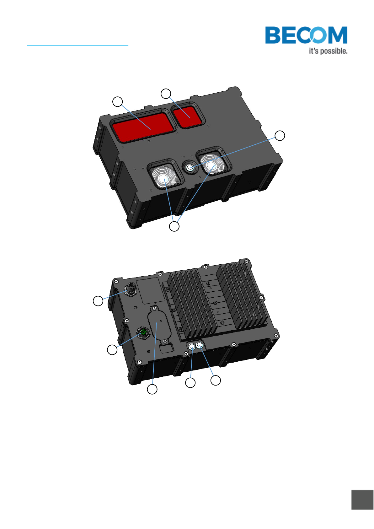
2TOREO-P650 Components
a
b
c
d
Figure 2-1 TOREO-P650 components (frontside)
h
f
e
g
i
Figure 2-2 TOREO-P650 components (backside)
a. Illumination window
b. ToF sensor window
c. RGB sensors
d. Status LED

© BECOM Systems 2021
9| 25
Hardware User Manual - TOREO-P650
Last change: 6 September 2021/Version 1
e. IP67 compliant M12 connector for power supply and I/Os
f. IP67 compliant M12 connector for gigabit Ethernet
g. Service opening
h. Ethernet activity LED
i. Ethernet link status LED

© BECOM Systems 2021
10 | 25
Hardware User Manual - TOREO-P650
Last change: 6 September 2021/Version 1
3Mechanical Description
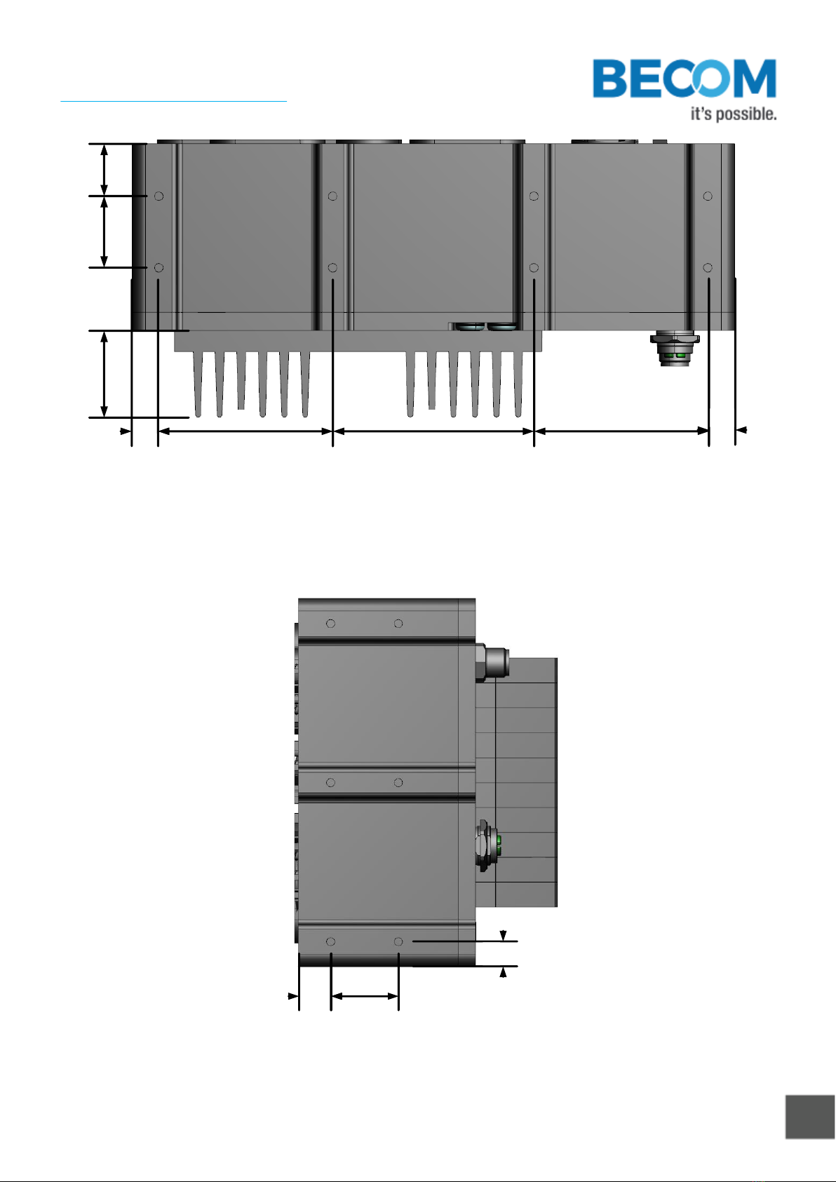
3.1 Dimensions
All dimensions are in mm, tolerance +/-0,2mm.
3.1.1 Front view
230,0
148,0
Figure 3-1: Front view dimensions
3.1.2 Long side view
Mounting hole size: M4
© BECOM Systems 2021
11 | 25
Hardware User Manual - TOREO-P650
Last change: 6 September 2021/Version 1
10,0
66,5 76,5 66,5 10,0
27,2 20
33,0
Figure 3-2: Long side view with mounting holes dimensions
3.1.3 Short side view
Mounting hole size: M4
13,0 27,2
10,0
Figure 3-3: Short side view

© BECOM Systems 2021
12 | 25
Hardware User Manual - TOREO-P650
Last change: 6 September 2021/Version 1
3.1.4 Mount Spacing
Caution
Case may become hot!
The user is responsible to take care for an appropriate cooling.
To prevent the TOREO-P650 from overheating, it is recommended, to keep away nearby objects. This guarantees a
constant airflow for proper cooling. This bounding box may be violated, when other cooling techniques are
provided.
30,0
Figure 3-4: Bounding box
© BECOM Systems 2021
13 | 25
Hardware User Manual - TOREO-P650
Last change: 6 September 2021/Version 1
4Interface Description
4.1 Signal naming
Signal names are usually written in capital letters. They are noted in positive logic (positive asserted). If the signal
is negative asserted an “n” will be added as prefix to the signal name.
Type:
The type describes the electrical characteristics of the signal. The following types are available:
•I Input
•O Output
•DN Negative Differential I/O
•DP Positive Differential I/O
•P Power supply
•3.3V TTL TTL compatible signal with 3.3V high level and 0V low level.
•50V tolerant Accepts input voltage levels up to 50V (2.5V high voltage threshold)
4.2 Connector Description
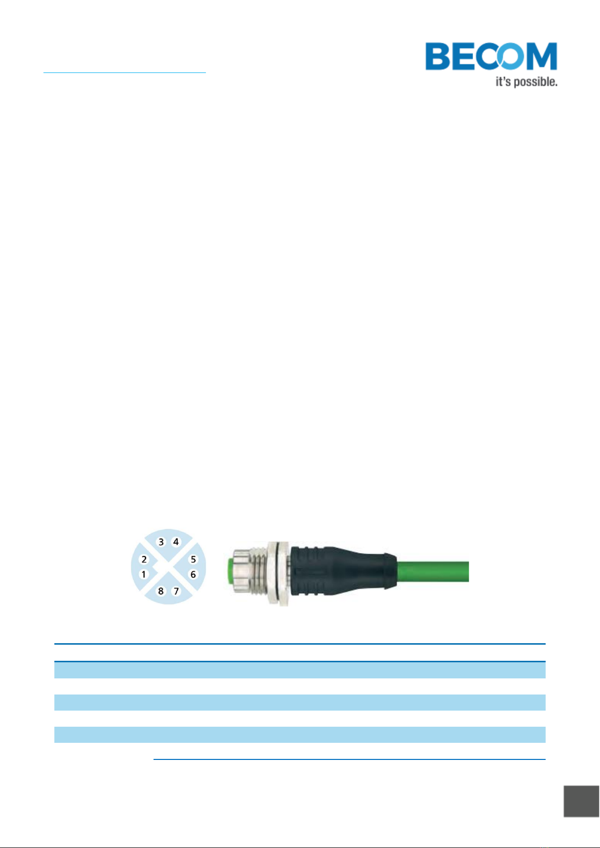
The TOREO-P650 has two IP67 compliant connectors: An eight pole X-coded M12 connector used for gigabit
ethernet communication, and a twelve pole M12 connector for power supply, and IOs.
Figure 4-1 M12 ethernet connector pinout
Pin No.
Name
Description
1
A -
Gigabit Ethernet Lane A negative
2
A +
Gigabit Ethernet Lane A positive
3
C -
Gigabit Ethernet Lane C negative
4
C +
Gigabit Ethernet Lane C positive
5
D -
Gigabit Ethernet Lane D negative
6
D +
Gigabit Ethernet Lane D positive
© BECOM Systems 2021
14 | 25
Hardware User Manual - TOREO-P650
Last change: 6 September 2021/Version 1
Pin No.
Name
Description
7
B -
Gigabit Ethernet Lane B negative
8
B +
Gigabit Ethernet Lane B positive
Table 4.1: M12 ethernet connector description
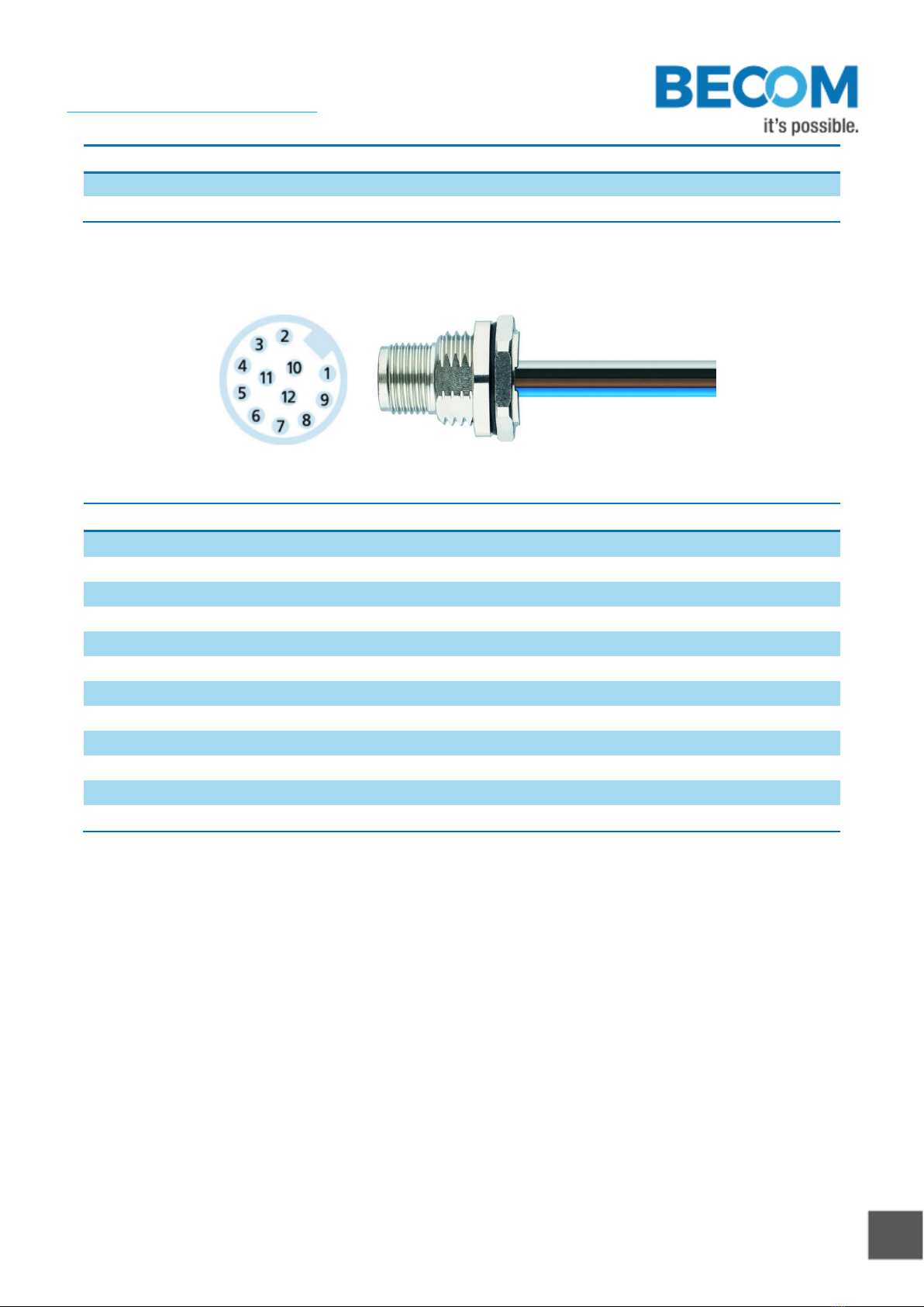
Figure 4-2 M12 power and IO connector Pinout
Pin No.
Name
IO-Type
Description
1
Vin
PWR
Positive Power Supply
2
Vin
PWR
Positive Power Supply
3
Vin
PWR
Positive Power Supply
4
TRIGGER
I
External trigger input / Recovery boot selection
5
nRESET
I
Camera reset input
6
OUT1
O
Solid state relay output 1
7
DGND
PWR
Reference ground for reset and trigger signals
8
OUT2
O
Solid state relay output 2
9
OUT_COM
O
Solid state relay common
10
GND
PWR
Power Ground
11
GND
PWR
Power Ground
12
GND
PWR
Power Ground
Table 4.2: M12 power and IO connector description
© BECOM Systems 2021
15 | 25
Hardware User Manual - TOREO-P650
Last change: 6 September 2021/Version 1
4.3 Digital Inputs and Outputs
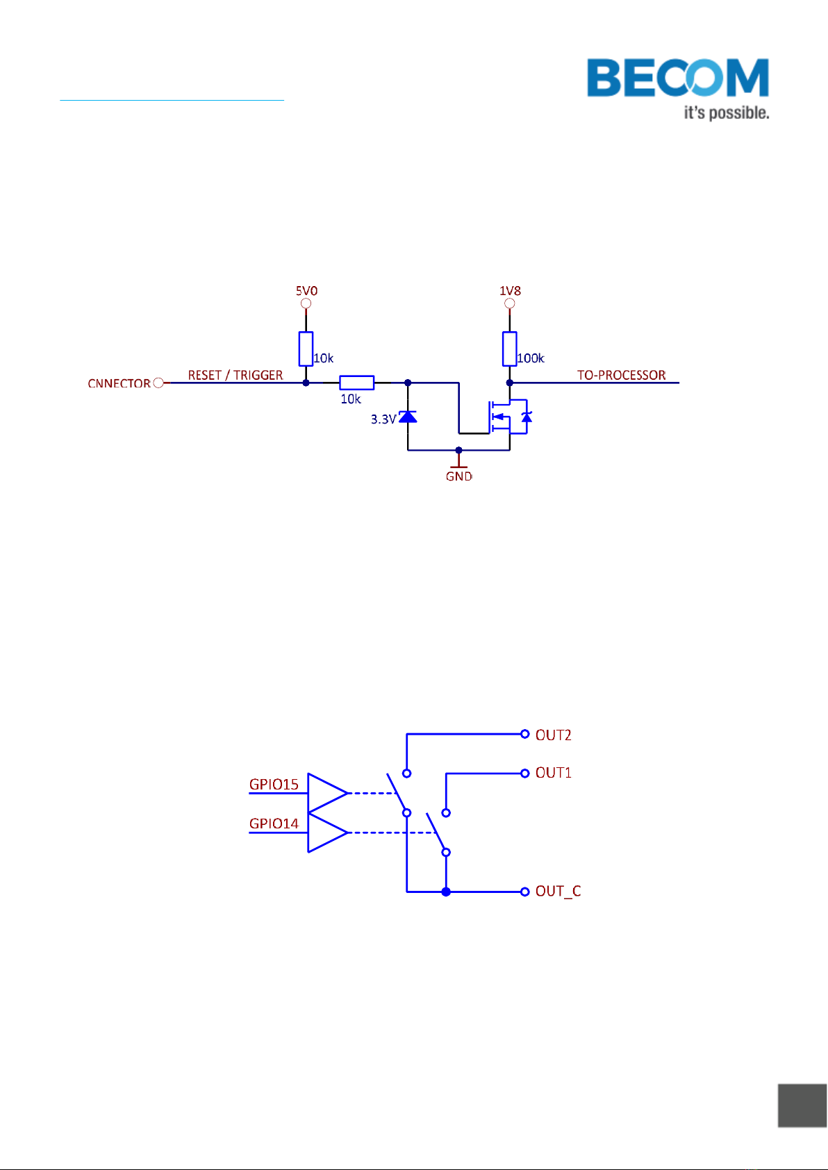
4.3.1 Input Stage
The implementation of the input stages for both digital inputs (reset and trigger) are shown in Figure 4-3.
Figure 4-3 Input Stage
The internal 10 kΩpull-up resistor allows to assert the signals by just shorting the pin to the corresponding
reference ground. But also applying a voltage (limited to 36 V) to the pin is acceptable. The on/off threshold is
1.05 V.
4.3.2 Output Stage
The implementation of the output stages is shown in Figure 4-4.
Figure 4-4 Output Stage
The GPIOs 14 and 15 are routed to a dual solid-state relay (SSR) with one common pin. All three pins are
electrically isolated from the others on the M12 connector. The maximum current through each SSR is limited to
200 mA, the maximum allowed clamp voltage is 50 V.

© BECOM Systems 2021
16 | 25
Hardware User Manual - TOREO-P650
Last change: 6 September 2021/Version 1
4.4 Power supply
The operational voltage range is 20 V to 30 V. To prevent internal components from being damaged, the power
supply protection circuit turns off the power supply, if it is not within the specified boundaries.
1) Note
Use inherently limited power sources only!
2) Note
The power protection circuit delays the camera supply by approx. 5 s after the external supply
is turned on.

© BECOM Systems 2021
17 | 25
Hardware User Manual - TOREO-P650
Last change: 6 September 2021/Version 1
5Electrical Specification
5.1 Absolute maximum rating
Stresses above the absolute maximum ratings listed in Table 5.1 may cause permanent damage to the device.
These are stress ratings only and functional operation of the device at these conditions is not implied. Exposure to
maximum rating conditions for extended periods may affect device reliability.
Symbol
Parameter
Conditions
Min
Max
Unit
VIN
DC supply voltage
-40
40
V
VIRST
Reset Input
-0.3
36
V
VITRG
Trigger Input
-0.3
36
V
TA
Ambient temperature
-40
60
°C
Table 5.1: Absolute maximum ratings
5.2 Operating conditions
Symbol
Parameter
Conditions
Min
Max
Unit
VIN
DC supply voltage
20
30
V
IIN_INT
Input supply current during integration
Vin = 24 V
6.55
A
IIN_IDL
Input supply between integration phases
Vin = 24 V
0.4
A
PINT
Peak Input Power during integration
Vin = 24 V
157.2
W
VIH
Reset and trigger input high level
1.2
30
V
VIL
Reset and trigger input low level
1.2
30
V
ISR
Solid state relay input current
0
200
mA
RSR_ON
Solid state relay on resistance
10
Ω
Table 5.2: Operating conditions

© BECOM Systems 2021
18 | 25
Hardware User Manual - TOREO-P650
Last change: 6 September 2021/Version 1
6Software
6.1 Firmware
For a description of the firmware related interfaces, protocol descriptions, register settings, etc. please refer to
the Software User Manual.
6.2 Demo Application
For the first evaluation of the camera and to evaluate different settings and configurations a .NET demo
application for Microsoft Windows is provided: BLT-ToF-Suite. The demo application can be downloaded from our
support web site http://systems.becom-group.com/support.
6.3 Getting Started Software Development Example
To facilitate the integration of the Argos module in your own application a getting started example will be
available on our download site. Please refer to our support site http://systems.becom-group.com/support.

© BECOM Systems 2021
19 | 25
Hardware User Manual - TOREO-P650
Last change: 6 September 2021/Version 1
7Appendix
7.1 Operating Conditions
7.1.1 Input current
The average input current depends on the selected frame-rate (fps) and the integration time (tINT). The following
figure shows typical values. The values on the x axis shows the FITP which has been calculated with the following
equation:
TBD
Figure 7-1: Input current @24V depending on frame-rate integration time product
7.1.2 Temperature at the case
The following figure shows the expected case temperature @ 25°C ambient temperature depending on the
frame-rate integration time product (FITP). The FITP has been calculated as follow:
TBD
Figure 7-2: Expected cooling plate temperature depending on frame-rate integration time product
The temperature on the casing can be reduced by mounting an additional heat sink on the cooling plate.
Caution
The user is responsible to take care for an appropriate cooling if the Argos camera is mounted
into a case.
Caution
Be careful to not stress the device beyond the limits, otherwise you may damage the device.

© BECOM Systems 2021
20 | 25
Hardware User Manual - TOREO-P650
Last change: 6 September 2021/Version 1
7.2 Optical Characteristics
Symbol
Parameter
Min
Typical
Max
Unit
#LDs
Amount of VCSEL laser diodes
16
ΛCENTROID
Centroid-Wavelength of Illumination
850
nm
Δλ
Spectral Bandwidth
30
nm
Ie
Radiant intensity
TBD
W/sr
FoV-ToFH
Horizontal Field of View
60
Deg
FoV-ToFV
Vertical Field of View
TBD
Deg
FoV-RGBH
Horizontal Field of View
TBD
Deg
FoV-RGBV
Vertical Field of View
TBD
Deg
RESToF
Spatial resolution ToF
640 x 480
Pixels
RESRGB
Spatial resolution RGB
13M
Pixel
Table 7-1: Sensor Characteristics
7.3 Performance
7.3.1 Measurement Conditions
All the following measurements have been acquired at the following constant environmental conditions.
Parameter
Value
Temperature
23 °C
Humidity
35 %
Ambient light
500 Lux
Table 7-2: Environmental Specification
The camera parameters for the ToF sensor are as follow:
Parameter
Value
Modulation Frequency
60 MHz
Frame-rate
20 fps
Integration time
0,6ms
Target Reflectivity
24%
Table 7-3: Camera Parameters
7.3.2 Precision
The following graph shows the standard deviation over 100 samples.
TBD
Other manuals for TOREO-P650
1
Table of contents
Other Becom Accessories manuals


