9487 Dielman Rock Island Ind Dr, St. Louis, MO 63132 www.becs.com
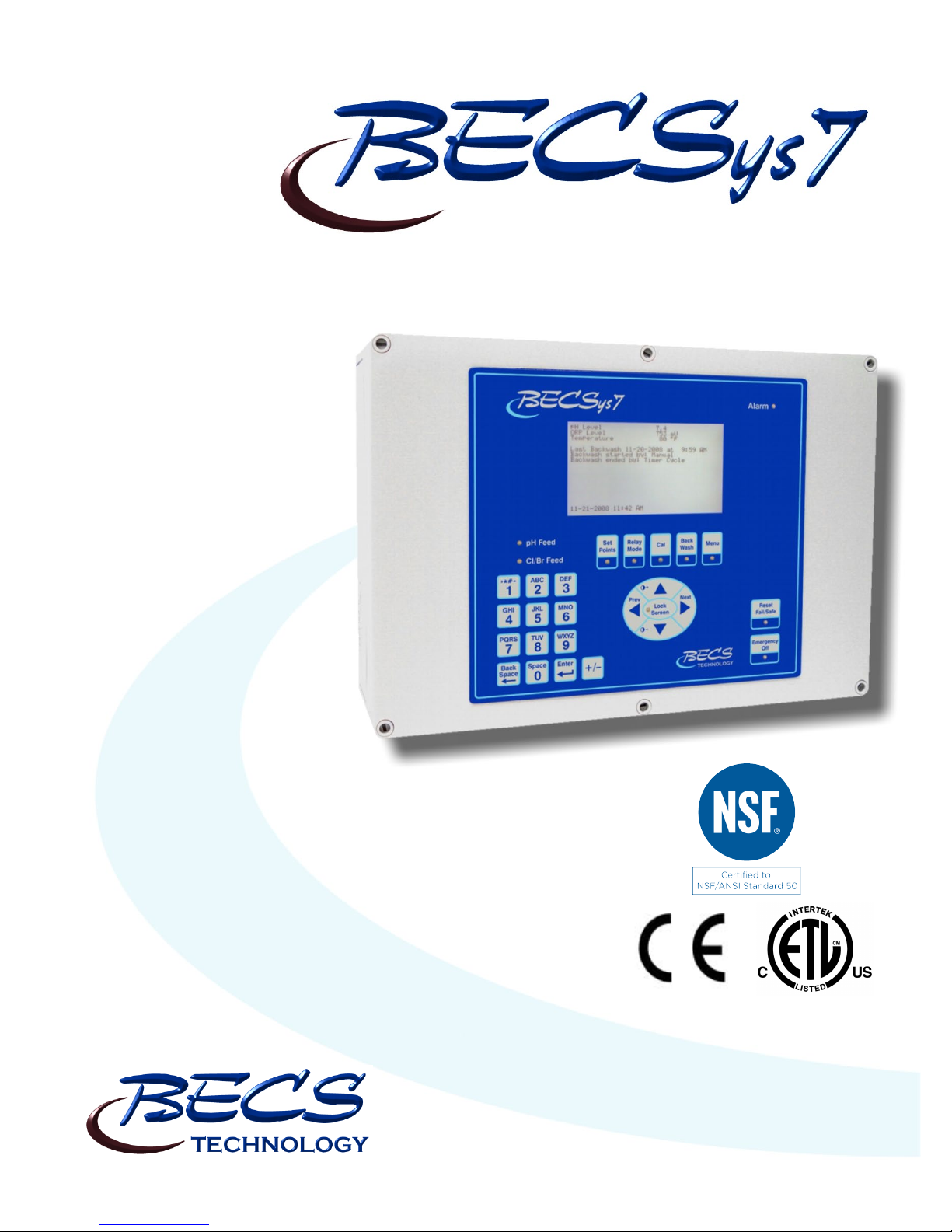
Operation and Maintenance Manual Rev: C17
TABLE OF CONTENTS
Warnings......................................................................... 1
General Guidelines ......................................................... 1
Firmware Version........................................................... 1
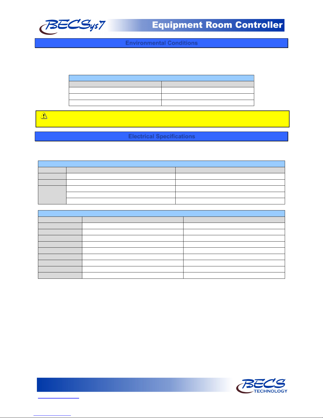
Environmental Conditions.............................................. 2
Electrical Specifications ................................................. 2
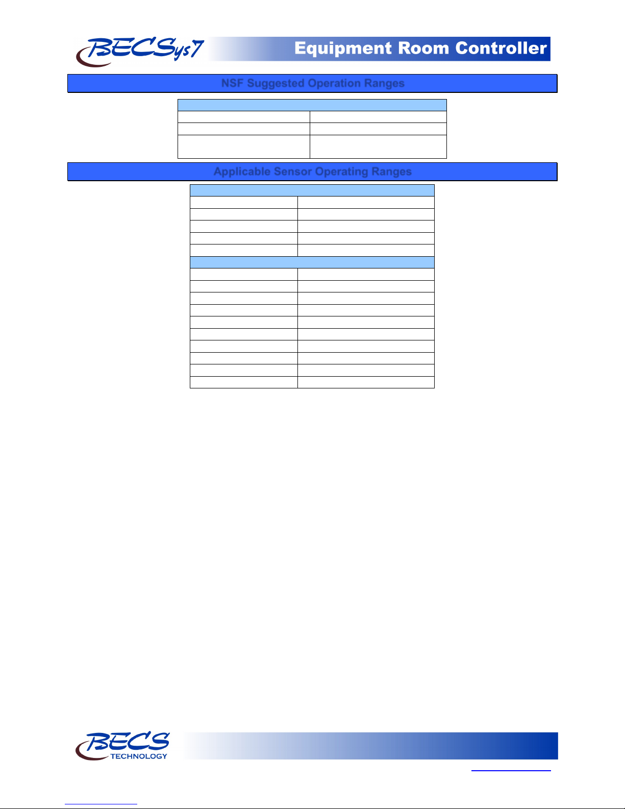
NSF Suggested Operation Ranges.................................. 3
Applicable Sensor Operating Ranges ............................. 3
Section A: Programming the Controller........................ 4
A – 1: Adjusting the Display Contrast....................... 4
A – 2: Security Settings............................................. 4
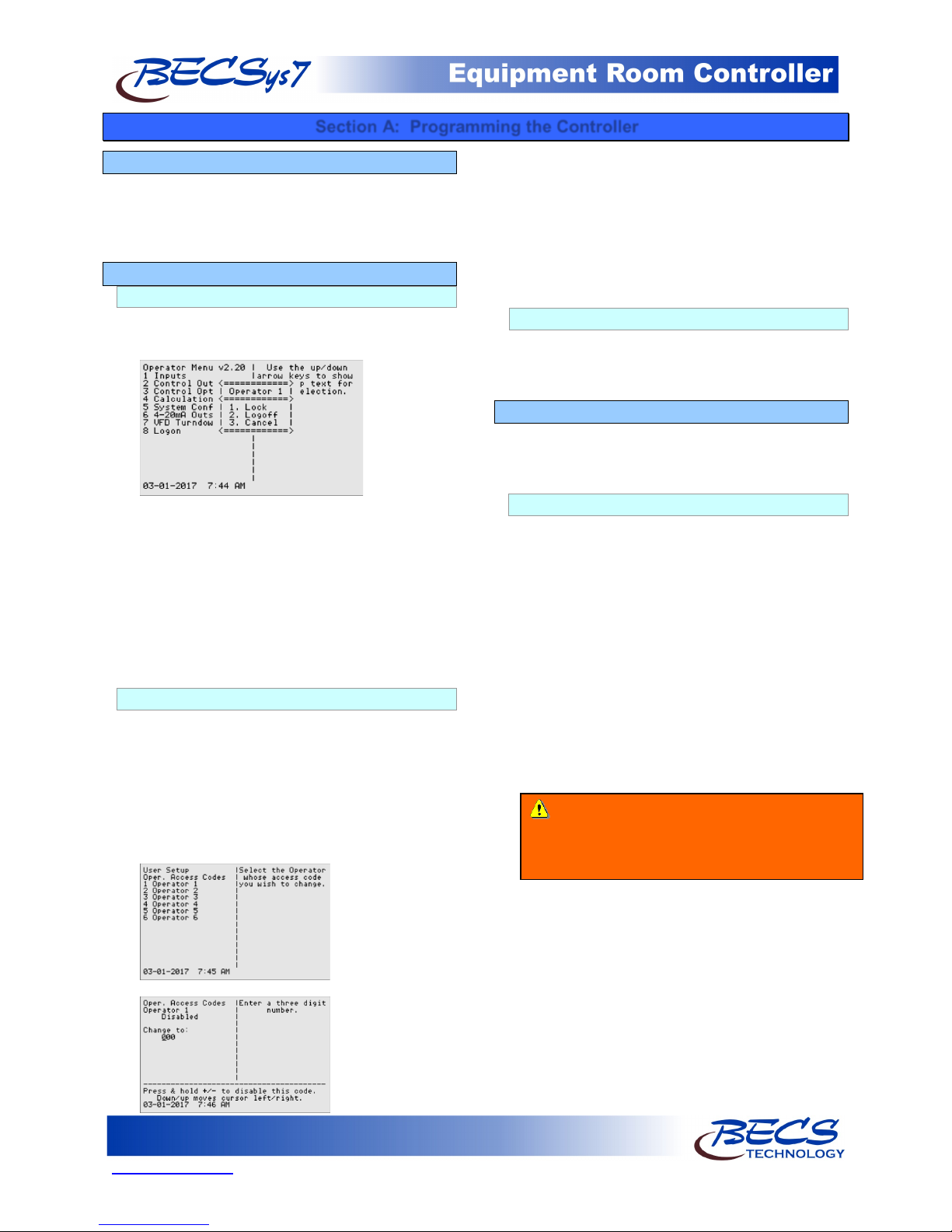
A – 2.1: Access Codes and levels.......................... 4
A – 2.2: Setting Access Codes............................... 4
A – 3: Navigating the menus ..................................... 4
A – 3.1: Common status messages ........................ 4
A – 3.2: The Menu Screens ................................... 5
A – 3.3: The Lock Screen Key .............................. 6
A – 4: Inputs .............................................................. 6
A – 4.1: pH Setup.................................................. 6
A – 4.2: ORP Setup ............................................... 6
A – 4.3: Cl Inputs Setup ........................................ 7
A – 4.3.1: Free Cl Setup ..................................... 7
A – 4.3.2: Total Cl Setup.................................... 8
A – 4.3.3: Combined Cl...................................... 8
A – 4.4: Temperature Setup................................... 8
A – 4.5: Conductivity/TDS Setup.......................... 8
A – 4.6: Flow Rate Setup....................................... 8
A – 4.7: Combined Flow Rate............................... 8
A – 4.8: pH & Chlorine Inventory Setups ............. 8
A – 4.9: Turbidity.................................................. 9
A – 4.10: Surge Pit Level ...................................... 9
A – 4.11: Pressure & Vacuum Setup..................... 9
A – 4.11.1: Filter Influent Pressure.................... 9
A – 4.11.2: Filter Effluent Pressure ................... 9
A – 4.11.3: Filter Differential Pressure.............. 9
A – 4.11.4: Pump Effluent Pressure................... 9
A – 4.11.5: Strainer Vacuum........................... 10
A – 4.11.6: Total Dynamic Head..................... 10
A – 4.12: Backwash Pit Level ............................. 10
A – 5: Control Outputs ............................................ 11
A – 5.1: pH Control............................................. 11
A – 5.2: Chlorine Control.................................... 12
A – 5.3: Chlorine Booster Control....................... 14
A – 5.4: Super Chlorination................................. 14
A – 5.5: Dechlorination ....................................... 15
A – 5.6: Ozone Control........................................ 15
A – 5.7: Heater..................................................... 16
A – 5.8: Chiller.................................................... 16
A – 5.9: Autofill................................................... 16
A – 5.10: Bleed Valve ......................................... 17
A – 5.11: Filter Backwash ................................... 17
A – 5.12: Sensor Wash ........................................ 18
A – 5.13: Enzyme................................................ 19
A – 5.14: Polymer................................................ 19
A – 5.15: UV Turndown.......................................19
A – 5.16: Recirculation Pump ..............................19
A – 5.16.1: VFD Control...................................19
A – 5.16.1.1: Scheduled Turndowns .............20
A – 5.16.1.2: Manual Turndowns..................20
A – 6: Control Options.............................................21
A – 6.1: Flow Restored Feed Delay .....................21
A – 6.2: Power Saver............................................21
A – 6.3: pH Lockout.............................................21
A – 7: Calculations...................................................22
A – 7.1: Enter Parameters.....................................22
A – 7.2: LSI Setup................................................22
A – 8: System Configuration....................................22
A – 8.1: System Info.............................................22
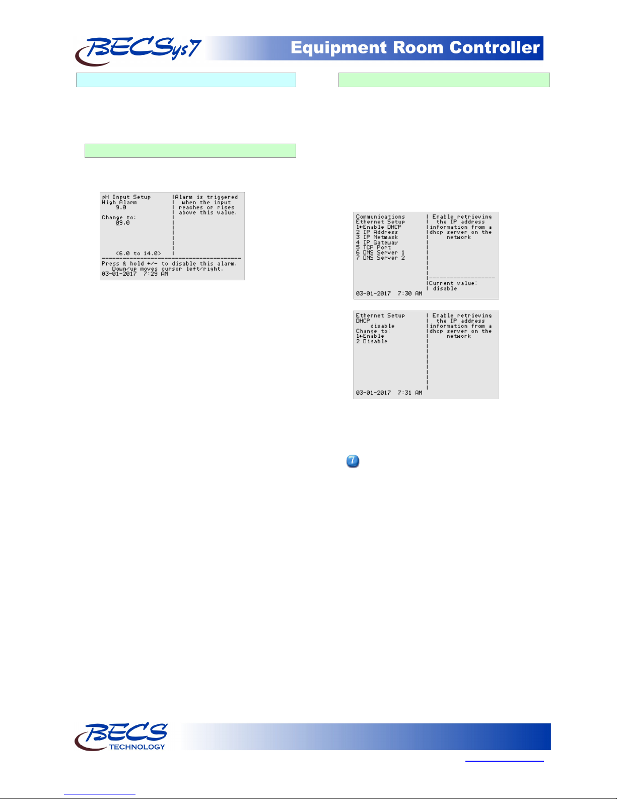
A – 8.2: Communication ......................................22
A – 8.2.1: EZConnect.......................................22
A – 8.2.2: Ethernet Setup .................................22
A – 8.2.3: SMTP Setup.....................................22
A – 8.2.4: Call Out Setup .................................23
A – 8.3: Date, Time & Units ................................23
A – 8.4: User Setup ..............................................23
A – 8.5: Display Options......................................24
A – 9: VFD Turndowns............................................24
A – 10: 4-20mA Outs...............................................24
A – 11: Access Menu ...............................................24
Section B: The Normal Display ...................................25
B – 1: Inputs and Feeds............................................25
B – 2: Alarms & Status messages.............................25
Section C: Using the Face Panel Quick Keys...............26
C – 1: The Set Points Key ........................................26
C – 2: The Relay Mode Key.....................................26
C – 3: The Cal Key (calibration)..............................27
C – 4: The Backwash Key........................................27
C – 5: The Reset Fail / Safe Key..............................28
C – 6: The Emergency Off Key................................28
Section D: BECSys for Windows.................................29
D – 1: System Requirements....................................29
D – 2: Installation.....................................................29
Section E: Maintenance................................................30
E – 1: Potentiometric Sensors (pH and ORP)...........30
E – 2: Free Chlorine Sensor (membrane).................30
E – 3: Free Chlorine Sensor (CP-1)..........................31
E – 3.1: Long Term Storage.................................31
E – 3: Total Chlorine Sensor ....................................31
E – 4: Conductivity Sensor.......................................32
Section F: Feed Charts .................................................33
F – 1: Spa Feed Charts .............................................33
F – 2: Pool Feed Charts............................................34
Section G: Replacement / Maintenance Parts...............35
Section H: Warranty.....................................................37