9487 Dielman Rock Island Ind Dr, St. Louis, MO 63132 www.becs.com
Operation and Maintenance Manual
Rev:
K12
T
TA
AB
BL
LE
E
O
OF
F
C
CO
ON
NT
TE
EN
NT
TS
S
Warnings............................................................................. 1
General Guidelines ............................................................. 2
Firmware Version ............................................................... 2
Environmental Conditions.................................................. 2
Electrical Specifications...................................................... 2
NSF Suggested Operation Ranges...................................... 3
Applicable Sensor Operation Ranges ................................. 3
Section A: Programming the Controller ............................ 4
A – 1: Controller Options .............................................. 4
A – 2: The Program Menu............................................. 4
A – 2.1: Entering the Program Menu......................... 4
A – 2.2: Selecting Language...................................... 4
A – 2.3: pH High Alarm Point................................... 4
A – 2.4: pH Low Alarm Point.................................... 4
A – 2.5: ORP High Alarm Point................................ 4
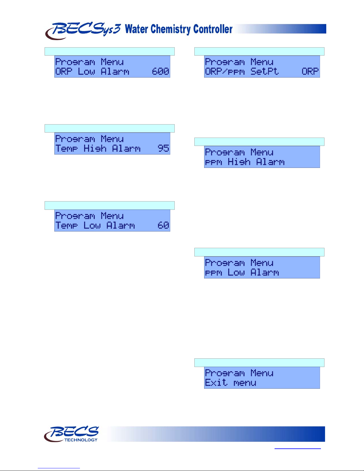
A – 2.6: ORP Low Alarm Point................................. 5
A – 2.7: Temperature High Alarm Point.................... 5
A – 2.8: Temperature Low Alarm Point .................... 5
A – 2.9: ORP/ppm Set point ...................................... 5
A – 2.10: ppm High Alarm ........................................ 5
A – 2.11: ppm Low Alarm......................................... 5
A – 2.12: Exiting the Menu........................................ 5
Section B: Normal Operation............................................. 6
B – 1: Set points............................................................. 6
B – 1.1: Displaying the Set points.............................. 6
B – 1.2: Modifying the Set points.............................. 6
B – 1.2.1: pH Set Point .......................................... 6
B – 1.2.2: Chlorine Set Point ................................. 6
B – 1.2.2.1: ORP Control................................... 6
B – 1.2.2.2: ppm Control (Calculated)............... 6
B – 1.2.2.3: ppm Control (Probe)....................... 6
B – 1.2.3: Booster Trigger Point............................ 6
B – 1.2.4: Booster End Point.................................. 6
B – 2: Single Point Calibration...................................... 7
B – 2.1: Single Point Calibration - pH....................... 7
B – 2.2: Single Point Calibration - Temp................... 7
B – 2.3: Single Point Calibration – ppm.................... 7
B – 2.3.1: Calculated ppm...................................... 7
B – 2.3.2: ppm Probe ............................................. 7
B – 2.4: Probe Error................................................... 7
B – 3: Alarms................................................................. 7
B – 3.1: pH High/Low alarms.................................... 7
B – 3.2: ORP High/Low alarms................................. 7
B – 3.3: ppm High/Low alarms.................................. 7
B – 3.4: Temperature High/Low alarms .................... 7
B – 3.5: No Flow Alarm............................................. 8
B – 3.6: Flow Restored Delay.................................... 8
B – 3.7: Cl/Br Lockout............................................... 8
B – 3.8: pH Failsafe................................................... 8
B – 3.9: Cl/Br Failsafe ............................................... 8
B – 3.10: Booster FAILSAFE.................................... 8
B – 4: Resetting a Failsafe Alarm.................................. 8
Section C: Using the BECSysRCM3................................. 9
C – 1: Monitoring a Controller.......................................9
C – 2: Downloading Data Logs......................................9
C – 2.1: Using a Flash Drive....................................10
C – 2.1.1: Importing Data Logs............................11
C – 3: Viewing Data Logs............................................11
Section D: Troubleshooting..............................................12
D – 1: BECSys3 ...........................................................12
D – 1.1: Probe Error.................................................12
D – 2: BECSysRCM3...................................................12
D – 2.1: Problems Using A Flash Drive...................12
D – 2.2: Text Message Call-Out Test.......................12
Section E: Maintenance....................................................13
E – 1: Potentiometric Sensors (pH and ORP)...............13
E – 1.1: Electrode Cleaning:.....................................13
E – 1.2: Long-Term Storage:....................................13
E – 2: CCS140 Free Chlorine Sensor...........................13
E – 2.1: Cleaning......................................................13
E – 2.2: Long-Term Storage.....................................13
E – 2.3: Filling electrolyte........................................13
Section F: Feed Charts .....................................................14
F – 1: Spa Feed Charts .................................................14
F – 2: Pool Feed Charts................................................15
Section G: Installation Diagrams......................................16
G – 1: Pressure Filter Installation.................................16
G – 2: Vacuum Filter Installation.................................16
Section H: Replacement Parts..........................................17
Section I: Warranty ..........................................................18