BECS BECSys3 115VAC User manual

Installation and Technical Manual


9487 Dielman Rock Island Ind Dr, St. Louis, MO 63132 www.becs.com
Installation and Technical Manual Rev: H10
T
TA
AB
BL
LE
E
O
OF
F
C
CO
ON
NT
TE
EN
NT
TS
S
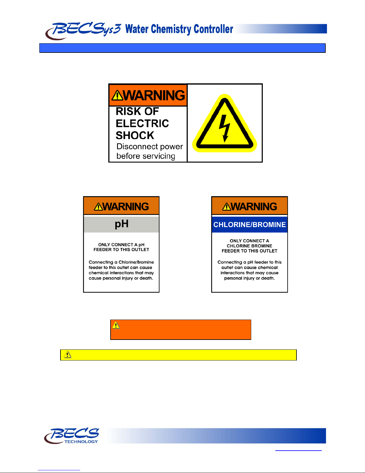
Warnings............................................................................. 1
Unpacking........................................................................... 2
General Guidelines ............................................................. 2
Firmware Version ............................................................... 2
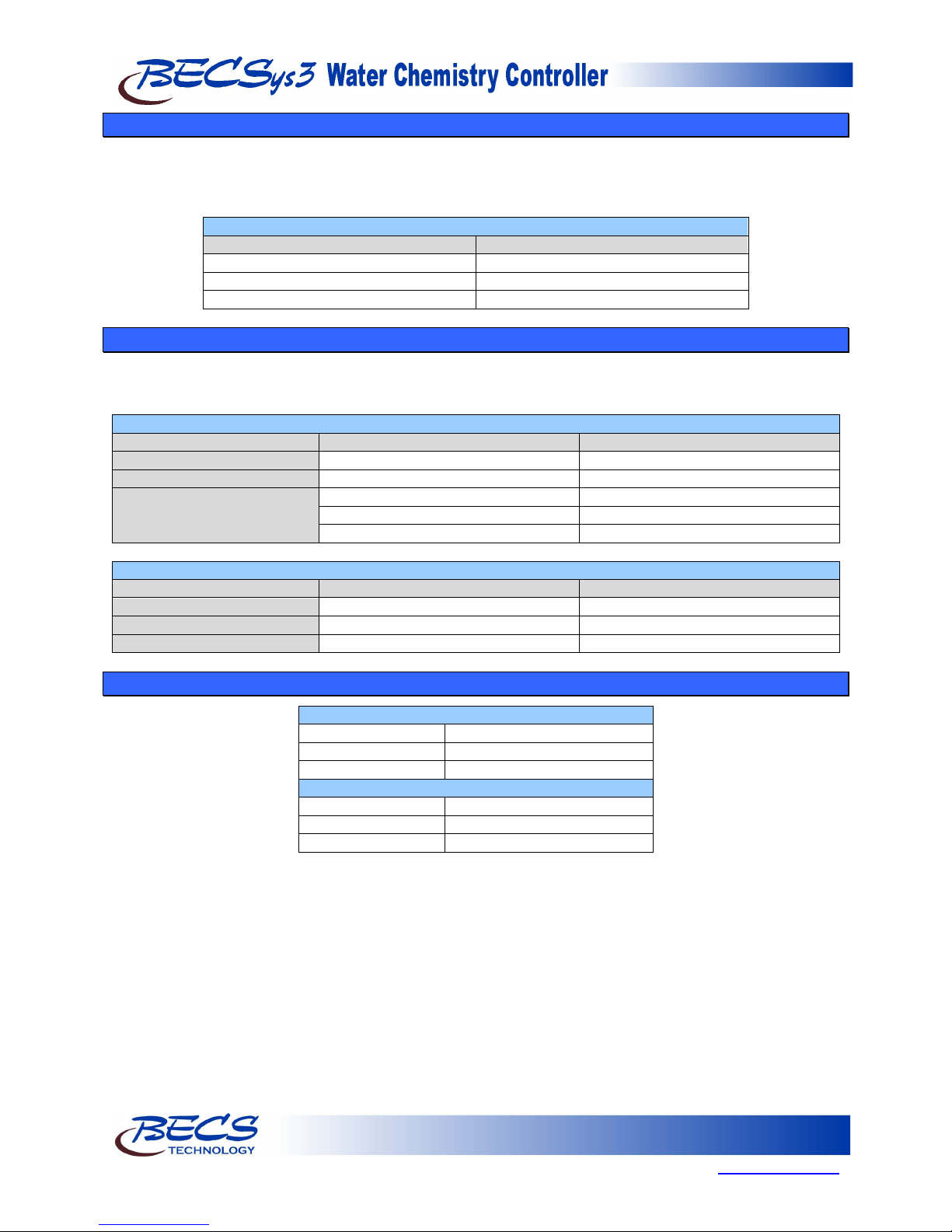
Environmental Conditions .................................................. 3
Electrical Specifications...................................................... 3
Applicable Sensor Operating Ranges.................................. 3
Section A: Mounting the BECSys3 Controller.................. 4
A – 1: Mounting the Controller...................................... 4
A – 2: Wrapping the Fittings.......................................... 4
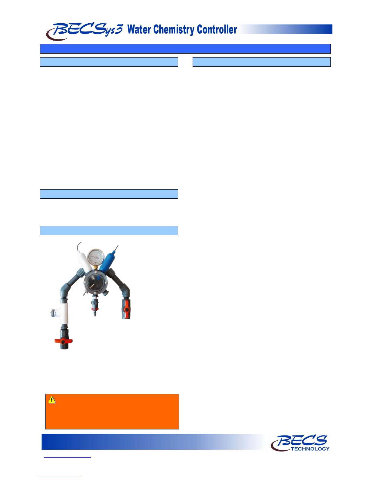
A – 3: Assembling the Flow cell.................................... 4
A – 4: Plumbing the Sample Stream.............................. 4
A – 5: Free Chlorine Sensor........................................... 5
A – 5.1: CCS140........................................................ 5
A – 5.2: ECL6............................................................ 5
A – 6: Sensor Preparations............................................. 6
A – 6.1: Sensors......................................................... 6
A – 7: Opening the Sample Stream Valve ..................... 6
A – 8: Plugging in the Sensors....................................... 6
Section B: Wiring the BECSys3 Controller....................... 7
B – 1: Wiring the Unit ................................................... 7
B – 2: Opening the Cover .............................................. 7
B – 3: Removing the Safety Shield................................ 7
B – 4: Disconnecting the Ribbon Cable......................... 8
B – 5: Wiring Directly to the Unit ................................. 8
B – 6: Wiring Power ...................................................... 8
B – 7: Supplying Power To The Relays......................... 8
B – 8: Wiring Relay 1.................................................... 9
B – 8.1: Line Powered ............................................... 9
B – 8.2: Common Powered........................................ 9
B – 9: Wiring Relay 2.................................................... 9
B – 9.1: Line Powered ............................................... 9
B – 9.2 Common Powered.......................................... 9
B – 10: Wiring Relay 3 ................................................ 10
B – 10.1: Line Powered ........................................... 10
B – 10.2: Common Powered.................................... 10
B – 11: Wiring a Flow Switch ..................................... 10
B – 11.1: Paddlewheel Flow Switch........................ 10
B – 11.2: Reed Flow Switch .................................... 11
B – 12: Wiring a Timer................................................ 11
B – 13: Wiring the Temperature Sensor ...................... 11
B – 14: Wiring a Free Chlorine Sensor........................ 11
B – 14.1: CCS140.................................................... 11
B – 14.2: ECL6........................................................ 11
B – 15: RS485 Network............................................... 12
B – 15.1: BECSys RCM .......................................... 12
B – 16: Fuses................................................................ 12
Section C: Dip Switch Settings........................................ 13
C – 1: Choosing pH Feed Direction............................. 13
C – 2: Choosing On/Off Control or TBP ..................... 13
C – 3: Relay 3 Functions.............................................. 13
C – 3.1: Probe Wash ................................................ 13
C – 3.2: Alarm Relay................................................13
C – 3.3: Dual pH Control .........................................14
C – 3.4: Cl/Br Booster..............................................14
C – 4: Temperature.......................................................14
C – 5: Replacing the Cover ..........................................14
Section D: Programming the Controller...........................15
D – 1: The Program Menu............................................15
D – 1.1: Entering the Program Menu .......................15
D – 1.2: Selecting Language ....................................15
D – 1.3: pH High Alarm Point..................................15
D – 1.4: pH Low Alarm Point ..................................15
D – 1.5: ORP High Alarm Point...............................15
D – 1.6: ORP Low Alarm Point ...............................15
D – 1.7: Temperature High Alarm Point..................16
D – 1.8: Temperature Low Alarm Point...................16
D – 1.9: ORP/ppm Set point.....................................16
D – 1.10: ppm High Alarm.......................................16
D – 1.11: ppm Low Alarm .......................................16
D – 1.12: Exiting the Menu......................................16
D – 2: The System Settings Menu................................17
D – 2.1: Entering the System Settings Menu............17
D – 2.2: ORP Span...................................................17
D – 2.3: pH Span......................................................17
D – 2.4: Time Base...................................................17
D – 2.5: pH Calibration (2 Point) .............................18
D – 2.6: ORP Calibration (2 Point) ..........................18
D – 2.7: Feed Delay..................................................18
D – 2.8: Enable ppm Set point Selection..................19
D – 2.9: Failsafe Timers...........................................19
D – 2.9.1: Booster Failsafe...................................19
D – 2.9.2: pH Failsafe ..........................................19
D – 2.9.3: Chlorine/Bromine Failsafe ..................19
D – 2.10: pH Dead-zone...........................................20
D – 2.11: Relay Test.................................................20
D – 2.12: ppm Probe Calibration..............................20
D – 2.12.1: CCS140 .............................................20
D – 2.12.2: ECL6 .................................................20
D – 2.13: Temperature Enable..................................20
D – 2.14: ORP Enable..............................................20
D – 2.15: Access Codes............................................21
D – 2.15.1: Operator Access Code.......................21
D – 2.15.2: Rep Access Code...............................21
D – 2.15.3: Recovering Lost Access Codes .........21
D – 2.16: Exiting The Menu.....................................21
Section E: Normal Operation ...........................................22
E – 1: Set points ...........................................................22
E – 1.1: Displaying the Set points ............................22
E – 1.2: Modifying the Set points.............................22
E – 1.2.1: pH Set Point.........................................22
E – 1.2.2: Chlorine Set Point................................22
E – 1.2.2.1: ORP Control..................................22
E – 1.2.2.2: ppm Control (Calculated)..............22

www.becs.com 9487 Dielman Rock Island Ind Dr, St. Louis, MO 63132
Installation and Technical Manual Rev: H10
E – 1.2.2.3: ppm Control (Probe)..................... 22
E – 1.2.3: Booster Trigger Point .......................... 22
E – 1.2.4: Booster End Point................................ 22
E – 2: Single Point Calibration .................................... 23
E – 2.1: Single Point Calibration - pH ..................... 23
E – 2.2: Single Point Calibration - Temp................. 23
E – 2.3: Single Point Calibration – ppm .................. 23
E – 2.3.1: Calculated ppm.................................... 23
E – 2.3.2: ppm Probe............................................ 23
E – 2.4: Probe Error................................................. 23
E – 3: Alarms............................................................... 23
E – 3.1: pH High/Low alarms.................................. 23
E – 3.2: ORP High/Low alarms ............................... 23
E – 3.3: ppm High/Low alarms................................ 23
E – 3.4: Temperature High/Low alarms................... 23
E – 3.5: No Flow Alarm........................................... 24
E – 3.6: Flow Restored Delay.................................. 24
E – 3.7: Cl/Br Lockout............................................. 24
E – 3.8: pH Failsafe ................................................. 24
E – 3.9: Cl/Br Failsafe ............................................. 24
E – 3.10: Booster FAILSAFE.................................. 24
E – 4: Resetting a Failsafe Alarm ................................ 24
Section F: Troubleshooting.............................................. 25
F – 1: Calibration Error................................................ 25
F – 2: Probe Error ........................................................ 25
Section G: Upgrading Firmware...................................... 25
Section H: Maintenance................................................... 26
H – 1: Potentiometric Sensors (pH and ORP).............. 26
H – 1.1: Electrode Cleaning:.................................... 26
H – 1.2: Long-Term Storage:................................... 26
H – 2: CCS140 Free Chlorine Sensor.......................... 26
H – 2.1: Cleaning..................................................... 26
H – 2.2: Long-Term Storage.................................... 26
H – 2.3: Filling electrolyte....................................... 26
Section I: Feed Charts...................................................... 27
I – 1: Spa Feed Charts.................................................. 27
I – 2: Pool Feed Charts................................................. 28
Section J: Installation Diagrams ...................................... 29
J – 1: Pressure Filter Installation.................................. 29
J – 2: Vacuum Filter Installation.................................. 29
Section K: Replacement Parts.......................................... 30
Section L: Warranty......................................................... 31

Page 1
9487 Dielman Rock Island Ind Dr, St. Louis, MO 63132 www.becs.com
Installation and Technical Manual Rev: H10
W
Wa
ar
rn
ni
in
ng
gs
s
Pay particular attention to the following warnings encountered in the pages of the
BECSys3 Installation and Technical Manual:
Warning: Various other warning boxes may be
found throughout the manual text.
Caution: Various other caution boxes may be found throughout the manual text.

Page 2
www.becs.com 9487 Dielman Rock Island Ind Dr, St. Louis, MO 63132
Installation and Technical Manual Rev: H10
U
Un
np
pa
ac
ck
ki
in
ng
g
Your Shipping package should contain these items:
A. The BECSys3 Controller
B. pH Sensor
D. Flow Cell Kit
E. Rotary or Reed flow switch
F. This manual (not shown)
G. Optional Sensors (not shown)
A B C D
G
Ge
en
ne
er
ra
al
l
G
Gu
ui
id
de
el
li
in
ne
es
s
Proper installation and use of the BECSys controller depends on the specific needs of the application. Read the manual
completely before starting the installation and ensure all guidelines and recommendations are followed. All components
should be mounted and the flow cell plumbing installed and pressure tested before wiring the controller. Ensure
compliance with all applicable plumbing and electrical codes during the installation as well.
F
Fi
ir
rm
mw
wa
ar
re
e
V
Ve
er
rs
si
io
on
n
This manual was written for firmware v2.06. If you received newer firmware but did not receive a copy of the manual
covering that version of firmware, please contact your distributor.
Warning: The Sensors are very fragile and must be handled with care. The tips of the probes must be kept
wet at all times, requiring the wetting caps to remain in place until they are ready to be installed. The probes
must be stored in temperatures above freezing.
Rotary
Reed
or
Caution: The BECSys controller should not be installed where it is accessible to the public.

Page 3
9487 Dielman Rock Island Ind Dr, St. Louis, MO 63132 www.becs.com
Installation and Technical Manual Rev: H10
E
En
nv
vi
ir
ro
on
nm
me
en
nt
ta
al
l
C
Co
on
nd
di
it
ti
io
on
ns
s
The BECSys3 is housed in a NEMA 4X (IP65) enclosure. It should not be used in explosive environments. The
BECSys3 should be mounted so that adequate ventilation is provided around the enclosure, preventing general
environmental specifications from being exceeded (see table below).
Environmental Specifications
Specification
Rating
Storage Temperature
-30 to 60 Deg C
Ambient Operating Temperature
-18 to 40 Deg C
Ambient Humidity
95% non condensing maximum humidity
E
El
le
ec
ct
tr
ri
ic
ca
al
l
S
Sp
pe
ec
ci
if
fi
ic
ca
at
ti
io
on
ns
s
The BECSys3 may be ordered in either an 115VAC model or a 230VAC model. Following are the electrical
specifications for each model:
Controller Ratings
115VAC Model
230VAC Model
Voltage:
115VAC 60Hz
230VAC 50Hz
Phase:
Single
Single
Current:
9.25 Amps Full Load
4.625 Amps Full Load
(¼ Amp – Controller)
(⅛ Amp – Controller)
(9 Amps – Relay Outputs, 3A X 3)
(4.5 Amps – Relay Outputs, 1.5A X 3)
Relay Output Ratings
115VAC Model
230VAC Model
Relay 1 (K1)
115VAC (max) – 3 Amps
250VAC (max) – 1.5 Amps
Relay 2 (K2)
115VAC (max) – 3 Amps
250VAC (max) – 1.5 Amps
Relay 3 (K3)
115VAC (max) – 3 Amps
250VAC (max) – 1.5 Amps
A
Ap
pp
pl
li
ic
ca
ab
bl
le
e
S
Se
en
ns
so
or
r
O
Op
pe
er
ra
at
ti
in
ng
g
R
Ra
an
ng
ge
es
s
Standard Sensors
pH
0.0 to 14.0 pH
Reed Flow Switch
Switch Point (On): 2.0 gpm
Rotary Flow Switch
Switch Point (On): 1.5 gpm
Optional Sensors
Temperature
32°F to 212°F (0°C to 100°C)
ORP
-1500mV to 1500mV
Amperometric ppm
0 ppm to 20 ppm

Page 4
www.becs.com 9487 Dielman Rock Island Ind Dr, St. Louis, MO 63132
Installation and Technical Manual Rev: H10
S
Se
ec
ct
ti
io
on
n
A
A:
:
M
Mo
ou
un
nt
ti
in
ng
g
t
th
he
e
B
BE
EC
CS
Sy
ys
s3
3
C
Co
on
nt
tr
ro
ol
ll
le
er
r
A – 1: Mounting the Controller
The BECSys3 Controller and flow cell are mounted
separately. The BECSys3 enclosure should be
mounted to the wall with four anchor bolts, one
installed in each corner of the enclosure base. To
mount the BECSys3 properly, please use the
included mounting template and hardware. Drill the
holes for the anchors using a 3/16” drill bit. Install
the anchors in the wall. Remove the lid from the
unit and place the included screws in the four
corners of the box. Attach the screws into the
anchors. The BECSys3 and flow cell should be
mounted in a location that is free from chemical
fumes and excessive heat, isolated from electrical
interference, and near a power source protected by a
ground fault interrupter. The BECSys3 has a
NEMA4 weather resistant enclosure but should still
be protected if mounted outdoors.
A – 2: Wrapping the Fittings
When assembling the flow cell, first open the bag of
flow cell fittings and wrap each fitting two times
around clockwise with Teflon tape.
A – 3: Assembling the Flow cell
Assemble the flow cell as shown below:
When installing the pH or ORP (if included) sensors,
remove the wetting cap, and then remove any
existing Teflon tape from the sensor threads. Re-
wrap the threads with new Teflon tape. Rinse the
sensor tip in de-ionized water and install as shown.
A – 4: Plumbing the Sample Stream
Install the sample stream; ½-inch tubing is
recommended for sample stream pickup and return.
Make sure that you tap the supply off the
discharge side of the recirculation pump,
upstream
of the chemical injection points. The
sample should be filtered water. Connect the sample
stream pickup line to the flow cell and run the
sample stream return line from the flow cell to the
suction side of the main recirculation pump. Install
½-inch ball valves to allow isolation of the sample
lines.
Warning: These sensors should be hand-
tightened only. Tools are not necessary for
installing the pH or ORP sensor and will
damage the sensor housing.

Page 5
9487 Dielman Rock Island Ind Dr, St. Louis, MO 63132 www.becs.com
Installation and Technical Manual Rev: H10
A – 5: Free Chlorine Sensor
The BECSys3 can be ordered to accept two different
Free Chlorine Sensors: the CCS140 or the ECL6.
A – 5.1: CCS140
The CCS140 Free Chlorine Sensor can be
connected to the BECSys3 using the appropriate
option board. The CCS140 Free Chlorine Sensor
is mounted in a flow cell which includes a flow and
psi restrictor assembly as shown below:
The CCS140 Free Chlorine Sensor requires a
constant flow rate and a constant pressure. This
helps ensure that the ppm level will remain stable.
Here is the recommended method for plumbing
the free chlorine sensor flow cell:
Admission pressure must be above the regulated
pressure (15 psi is the limit on the sensor). Run
the sample stream through a flow restrictor valve
(to maintain flow rate, minimum flow rate
requirement is 8 gph). Take the stream through
the flow cell. Discharge the sample stream to a
free outlet (for example into a surge tank).
The CCS140 Free Chlorine Sensor is supplied with
a yellow protective cap. This cap has an inner
sponge that is used to keep the sensor membrane
hydrated. This cap should be saved for long-term
storage.
The sensor can remain in the flow cell for short-
term interruptions in measurement. To prevent
membrane dehydration, the flow cell must not
drain off. If this is not ensured, then remove the
sensor from the flow cell and slide the yellow
protective cap, moistened at the inner sponge,
onto the measuring end of the sensor.
The voltage applied by the controller to the
CCS140 Free Chlorine Sensor polarizes the surface
of the gold cathode. The polarization period (30
minutes) must elapse before calibration is
performed based on the results acquired through
the use of a DPD test kit.
See Section H - 2.3 for filling the electrolyte.
A – 5.2: ECL6
The ECL6 Free Chlorine Sensor can be connected
to the BECSys3 using the appropriate option
board.
Caution: Amperometric chlorine sensors
require the use of a temperature sensor and
a properly calibrated pH sensor. Refer to
the instruction pamphlet included with the
sensor at the time of installation.
Warning: Negative pressure will damage the
sensor membrane.

Page 6
www.becs.com 9487 Dielman Rock Island Ind Dr, St. Louis, MO 63132
Installation and Technical Manual Rev: H10
A – 6: Sensor Preparations
NOTE: As soon as you install the sensors,
immediately move on to the next step to insure that
they always stay wet.
A – 6.1: Sensors
The pH and ORP (if included) sensors are shipped
with a wetting cap covering the measuring end.
This cap contains a solution of pH 4 buffer
saturated with potassium chloride (KCl). Gently
remove the wetting cap by unscrewing the sensor
and sliding the cap off of the sensor body.
It is a good idea to save the wetting cap and
the box that the sensor came in for future
long-term storage.
During shipping, the air space inside the pH glass
may have moved into the bulb. Grasp the sensor
near the cable end and gently swing it through an
arc to force the internal electrolyte into the pH
bulb. Rinse the measuring ends of potentiometric
sensors with de-ionized or distilled water before
installation into a flow cell.
A – 7: Opening the Sample Stream Valve
Open the sample stream valve and check for leaks.
Note the reading on the compound pressure gauge
and make sure that it shows a positive and steady
pressure. The sample stream should be about 2-20
psi at the flow cell. If this is not the case, then adjust
the valves or relocate the point at which the sample
stream is connected to the recirculation system.
Negative pressure will destroy the sensors. Once
you have a positive and steady pressure, open the wet
test valve and make sure that it generates a vigorous
stream.
A – 8: Plugging in the Sensors
Remove the protective covers from the BNCs. Plug
the pH sensor into the coded BNC jack and the
ORP (if included) sensor into the coded BNC jack
on the bottom of the BECSys3 controller by twisting
them a quarter of a turn. Allow the sensors to rinse
in the sample water while you do the wiring (Section
B).

Page 7
9487 Dielman Rock Island Ind Dr, St. Louis, MO 63132 www.becs.com
Installation and Technical Manual Rev: H10
S
Se
ec
ct
ti
io
on
n
B
B:
:
W
Wi
ir
ri
in
ng
g
t
th
he
e
B
BE
EC
CS
Sy
ys
s3
3
C
Co
on
nt
tr
ro
ol
ll
le
er
r
B – 1: Wiring the Unit
There are several ways that you can wire the relays and
power to the unit. The easiest is to use the cords
already installed in the unit. Plug the AC Cord into a
GFCI outlet (only for low voltage 110VAC-120VAC
applications) and connect the chemical feeders to the
female power cords (pigtails). The pigtails are labeled
with the below warning tags. Be sure to connect the
correct pigtail to the correct chemical feeder. You
must still remove the cover to install the Flow Switch,
and any other optional components.
The second way is to discard the pre-installed cords
and wire the unit directly.
B – 2: Opening the Cover
In order to wire the unit directly or attach the Flow
Switch (and any optional components), you must
open the cover. Remove the cover by loosening the
four screws at the corners with a screwdriver as
shown. NOTE: The screws do not need to be
totally removed, but only loosened. Once the
screws are loosened, carefully lift the top cover off of
the unit. The cover will still be connected to the
base by the ribbon cable. Set the moisture absorbent
packet found inside aside for now.
B – 3: Removing the Safety Shield
To remove the shield, remove the four screws using
a Philips screwdriver. Gently lift the cover straight
up and set it to the side.

Page 8
www.becs.com 9487 Dielman Rock Island Ind Dr, St. Louis, MO 63132
Installation and Technical Manual Rev: H10
B – 4: Disconnecting the Ribbon Cable
We recommend that you disconnect the ribbon cable
by spreading the two holders at the end of the cable
attached to the cover as shown, unplugging the cable
and removing the cover.
NOTE: Be sure to store the cover in a safe, dry
place while you wire and set up the unit.
B – 5: Wiring Directly to the Unit
To wire the unit directly, you must remove the pigtails
already installed. You may use the ½-inch holes in the
casing to enable you to easily run wires to Terminal
Block 1 (TB1) inside the base of the unit.
NOTE: There are Terminal Blocks labeled TB1
and TB2 in both the cover and base of the
unit and they serve different functions.
Use the ½-inch cord grips provided and whatever
holes are convenient, but when you are all finished
wiring the unit, be sure to plug any unused holes with
a ½-inch NEMA 4x plug.
B – 6: Wiring Power
The main power input should be wired to TB1. The
black wire goes into the position labeled Line, the
white wire goes into the position labeled Neutral, and
the green wire goes into the position labeled Earth
Ground.
NOTE: The black and white wires are colored
brown and blue outside North America.
B – 7: Supplying Power To The Relays
All three of the relays may be configured to be
powered from either the L (Line) connection which
the controller itself is powered from, or their
individual C (Common) connections. As shipped
from the factory, all three relays are configured to be
powered from the L (Line) power connection. If
you wish to use the C (Common) input instead
(commonly used to interlock feeds with the
recirculation pump), you will need to move the black
hat jumpers located above TB2 to their upper
position for the desired relays.
NOTE: The relays inside the controller are solid-
state and can only switch AC signals. If
you need to switch DC power, an
external Mechanical Relay must be used.
Warning: Make sure power is disconnected
while you wire the unit
Warning: Unless specified at time of order,
controllers are configured for 115VAC and
should not be used at 230VAC. Always contact
BECS Technology, Inc. before attempting to
reconfigure a controller’s input supply voltage.

Page 9
9487 Dielman Rock Island Ind Dr, St. Louis, MO 63132 www.becs.com
Installation and Technical Manual Rev: H10
B – 8: Wiring Relay 1
Relay 1 controls pH. You can configure the relay to
be powered from the same Line voltage as the
controller or from its own separate voltage input.
B – 8.1: Line Powered
Make sure the hat jumper is in the lower position
“L”. The black wire goes into the position labeled
pH Feed, the white wire goes into the Neutral
position next to that, and the green wire goes into
Earth Ground position next to that. Nothing
should be connected to the pH COM terminal.
NOTE: The black and white wires are colored
brown and blue outside North America.
B – 8.2: Common Powered
Connect the incoming power to the pH COM
terminal (the red wire shown below) and move the
hat jumper for the pH relay to the upper position
“C”. The black wire goes into the position labeled
pH Feed. Leave the Neutral and Earth Ground
terminals unconnected inside the controller. The
Neutral and Earth Grounds from the feeder must
be connected to the Neutral and Earth Ground of
the power source supplying this relay.
B – 9: Wiring Relay 2
Relay 2 controls ORP. You can configure the relay
to be powered from the same Line voltage as the
controller or from its own separate voltage input.
B – 9.1: Line Powered
Make sure the hat jumper is in the lower position
“L”. The black wire goes into the position labeled
Cl/Br Feed, the white wire goes into the Neutral
position next to that, and the green wire goes into
the Earth Ground position next to that. Nothing
should be connected to the Cl/Br COM terminal.
NOTE: The black and white wires are colored
brown and blue outside North America.
B – 9.2 Common Powered
Connect the incoming power to the Cl/Br COM
terminal (the red wire shown below) and move the
hat jumper for the Cl/Br relay to the upper
position “C”. The black wire goes into the
position labeled Cl/Br Feed. Leave the Neutral
and Earth Ground terminals unconnected inside
the controller. The Neutral and Earth Grounds
from the feeder must be connected to the Neutral
and Earth Ground of the power source supplying
this relay.

Page 10
www.becs.com 9487 Dielman Rock Island Ind Dr, St. Louis, MO 63132
Installation and Technical Manual Rev: H10
B – 10: Wiring Relay 3
Relay 3 may be used for Dual pH control, Alarm,
Cl/Br Booster, or Sensor Wash (Refer to Section C
on how to configure this). You can configure the
relay to be powered from the same Line voltage as the
controller or from its own separate voltage input.
B – 10.1: Line Powered
Make sure the hat jumper is in the lower position
“L”. The black wire goes into the position labeled
Auxiliary, the white wire goes into the Neutral
position next to that, and the green wire goes into
Earth Ground position next to that. Nothing
should be connected to the AUX COM terminal.
NOTE: The black and white wires are colored
brown and blue outside North America.
B – 10.2: Common Powered
Connect the incoming power to the AUX COM
terminal (the red wire shown below) and move the
hat jumper for the Aux relay to the upper position
“C”. The black wire goes into the position labeled
Auxiliary. Leave the Neutral and Earth Ground
terminals unconnected inside the controller. The
Neutral and Earth Grounds from the feeder/device
must be connected to the Neutral and Earth
Ground of the power source supplying this relay.
B – 11: Wiring a Flow Switch
A Flow Switch must be used in the operation of a
BECSys3 Controller.
A paddlewheel flow switch or reed flow switch is
incorporated into the flow cell to disable chemical
feed in the event of loss of flow.
B – 11.1: Paddlewheel Flow Switch
Connect the wires to CN5 in the cover of the unit.
The black wire goes to Ground, the white wire
goes to Flow, and the red wire goes to +12V.
With the paddlewheel flow switch, whenever the
wheel spins, the green “flow” light on the flow
switch will be on.
Warning: NEVER BYPASS FLOW
SWITCH CONNECTIONS
The Flow Switch is a critical safety device which
prevents uncontrolled chemical feed.
Uncontrolled feeding of chemicals can result in
injury or death.
Warning: Failure to incorporate a Flow
Switch and Flowcell into the sample
Stream of your BECSys chemical controller
can result in injury or death to swimmers in or
around the pool if the recirculation pump
should fail or shut down.
Warning: A check valve must be installed with
the paddlewheel flow switch to prevent backflow
when the system is shut down. If a check valve is
not installed, backflow could give the controller a
false reading of flow and continue to pump
chemicals into the pool.

Page 11
9487 Dielman Rock Island Ind Dr, St. Louis, MO 63132 www.becs.com
Installation and Technical Manual Rev: H10
B – 11.2: Reed Flow Switch
The reed flow switch is a (2) two-wire switch.
Connect the wires to CN5 in the cover of the unit.
The black wire goes to the terminal labeled Flow,
and the red wire goes to the terminal labeled + 12.
NOTE: Unlike the paddlewheel flow switch, the
reed flow switch is a directional switch.
Make sure it is installed with the flow
arrow in the proper direction. No check
valve is required with the reed flow switch.
B – 12: Wiring a Timer
One advantage of the BECSys3 Controller is that the
unit can be used with a timer to control the feeder and
still not lose power to the sensor. Most controllers
work with a timer by cutting all power, which then
means that the sensor goes through an erratic period
(up to two minutes) every time power is restored.
With BECS units, the sensor continues to function
even when the timer cuts power to the feeder so there
is never a loss in accuracy.
If you have decided to use a timer to interrupt the
chemical feed, wire the timer in parallel with the flow
lead of the flow switch.
Timer
Flow Switch
B – 13: Wiring the Temperature Sensor
The optional temperature sensor is wired to CN5 in
the cover of the unit. The white wire goes to the
terminal labeled "+", and the black wire goes to the
terminal labeled "-".
B – 14: Wiring a Free Chlorine Sensor
B – 14.1: CCS140
The CCS140 Free Chlorine Sensor is wired to the
option board inside the controller. If you ordered
your controller with the option board, it is located
on the lower left side of the lid. There is a three
position pluggable terminal block where the wires
will be connected. Connect the red "A" wire to
the A terminal, the "K" white tip with transparent
wire to the K terminal, and the thick unlabeled
wire to the ground terminal.
B – 14.2: ECL6
The ECL6 Free Chlorine Sensor is wired to the
option board inside the controller. If you ordered
your controller with the option board, it is located
on the lower left side of the lid. There is a two
position pluggable terminal block where the wires
will be connected. The red wire goes to the
position labeled “red” and the black wire goes to
the position labeled “black”.

Page 12
www.becs.com 9487 Dielman Rock Island Ind Dr, St. Louis, MO 63132
Installation and Technical Manual Rev: H10
B – 15: RS485 Network
B – 15.1: BECSys RCM
If you have ordered a BECSys RCM, or the site has
a BECSys RCM already installed, you may connect
your BECSys3 to it. The BECSys RCM provides
data logging and remote access of up to 32
BECSys3 controllers per site.
Recommended wire: 22 gauge shielded twisted pair
(1 pair: 2 conductors + shield).
For outdoor use, use NEC type PLTC.
For indoor use, use NEC type CMG general, CMR
riser (through floors), or CMP plenum as required
by the local wiring code.
Connect the wires to CN4 in the cover of the unit.
There are two RS485 terminal blocks to allow daisy
chaining of units. It doesn’t matter which
connector you use – whichever is easiest. For each
unit, wire as follows:
From BECSys3
To BECSys RCM
A
A
B
B
SH
Shield
Refer to the BECSys RCM manual (included with
your BECSys RCM) for more information on how
to configure the network.
B – 16: Fuses
115VAC Model (F4):
¼ Amp 250V Time Lag Fuse (¼” x 1¼”)
BECS Part Number: 8140086
230VAC Model (F4):
¼ Amp 250V Time Lag Fuse (¼” x 1¼”)
BECS Part Number: 8140086
Relay Fuses (F1 – F3):
3 Amp 250V Time Lag Fuse (¼” x 1¼”)
BECS Part Number: 9140088
RS485 Fuse (F1 CPU Board):
¼ Amp 250V Time Lag Microfuse (5.08mm)
BECS Part Number: 8140059

Page 13
9487 Dielman Rock Island Ind Dr, St. Louis, MO 63132 www.becs.com
Installation and Technical Manual Rev: H10
S
Se
ec
ct
ti
io
on
n
C
C:
:
D
Di
ip
p
S
Sw
wi
it
tc
ch
h
S
Se
et
tt
ti
in
ng
gs
s
The BECSys3 controller comes preprogrammed for
pH feed down (acid or CO2), Time Based Proportional
feed mode, Probe Wash, and temperature shown in °F.
These factory settings are appropriate for most
systems. If you would like to change these settings,
you must change the internal dipswitches.
To change the dipswitches, first unplug the BECSys3
power cord and open the cover of the unit (as
explained in Section B - 2).
The photograph shows the dipswitch bank (SW5) in
the cover of the unit.
The following chart indicates the positions and
functions of the switches.
Dip Switch
OFF
ON
1
pH Feed Down
pH Feed Up
2
pH TBP Control
pH On/Off Control
3
ORP TBP Control
ORP On/Off Control
4
NOT USED
5
NOT USED
6
Relay 3 Function*
7
Relay 3 Function*
8
Temperature °C Temperature °F
* See Section C – 3
C – 1: Choosing pH Feed Direction
Relay 1 controls pH. It can be set to feed down
(acid) for use with chemicals such as carbon dioxide
or muriatic acid, or to feed up (base) for use with
chemicals such as caustic soda or soda ash. (If you
are using Dual pH then Relay#1 is set as Feed Up
and Relay#3 is set as Feed Down).
C – 2: Choosing On/Off Control or TBP
In general, if you are using a motor driven chemical
feeder then you should choose the On/Off option.
If you are using a solenoid driven or pulsed
diaphragm chemical feeder (such as Pulsatron, most
LMI models or most Prominent Models), you should
choose the TBP (Time-Based Proportional) option.
This feature helps to hold a set point and to
minimize over-shoot by making a standard feeder
mimic the action of more sophisticated modulating
feeders.
If you choose the On/Off option and are feeding up
then the controller will activate the chemical feeder
whenever the pH or ORP falls below the set point
and continue to feed until the pH or ORP rises
above the set point plus hysteresis at which point it
will stop.
If you choose the TBP option the controller will
activate the chemical feeder whenever the pH or
ORP falls below the set point and will feed for a
fraction of the Time Base depending on the amount
of deviation from set point. The balance of the Time
Base, the feeder will be paused. The smaller the
deviation, the less time the feeder is ON. The feeder
will continue this feed and pause cycle until the
BECSys3 achieves the set point plus hysteresis.
C – 3: Relay 3 Functions
Relay 3 can be used for several different functions.
To select the function of Relay 3 move switches 6
and 7 to the positions shown in the following chart:
Dip Switch 6
Dip Switch 7
Function
Off
Off
Probe Wash
Off
On
Alarm
On
Off
Dual pH
On
On
Cl/Br Booster
NOTE: You will only have an Alarm Relay when
the dip switches are set accordingly. The
Alarm LED will still flash when the
controller is in Alarm.
C – 3.1: Probe Wash
Setting Dip Switches 6 and 7 to the off position
configures Relay 3 for Probe Wash. The Probe
Wash will begin 12 hours from power-up, run for
approximately 2 minutes, and then come on again
every 24 hours after that running for 2 minutes.
C – 3.2: Alarm Relay
Setting Dip Switch 6 to the off position and Dip
Switch 7 to the on position configures Relay 3 for
Alarm. The Alarm Relay will turn on any time
there is an alarm state (No Flow, pH High, etc).
Alarm points are set in the Programming Section
of this manual (Section D).

Page 14
www.becs.com 9487 Dielman Rock Island Ind Dr, St. Louis, MO 63132
Installation and Technical Manual Rev: H10
C – 3.3: Dual pH Control
Setting Dip Switch 6 to the on position and Dip
Switch 7 to the off position configures Relay 3 for
dual pH control (pH feed down).
C – 3.4: Cl/Br Booster
Setting Dip Switches 6 and 7 to the on position
configures Relay 3 for a sanitizer booster. When
the ORP level drops to the Cl/Br Booster Trigger
point, Relay 3 will activate an alternate sanitizer
feed until the ORP reaches the Cl/Br Booster End
point.
C – 4: Temperature
With Dip Switch 8 On, temperature is displayed in
Fahrenheit. With the Dip Switch Off, temperature is
displayed in Celsius.
C – 5: Replacing the Cover
Now it is time to put the cover back on the unit. But
before you do, give your wiring one last check and
make sure that you reconnect the ribbon cable (as
shown). Line up the small holes in the cable end
with the pins attached to the cover and gently press
the cable into place. Make sure the two holders
attached to the cover close back over the cable end
to hold it firmly in place.
Replace the safety shield using the screws that were
removed. Be sure to align the holes with the fuse
holders. You may have to adjust the fuse holders
slightly to align the shield properly. Finally, place the
cover back on the unit and tighten the four screws at
the corners to secure it in place.

Page 15
9487 Dielman Rock Island Ind Dr, St. Louis, MO 63132 www.becs.com
Installation and Technical Manual Rev: H10
S
Se
ec
ct
ti
io
on
n
D
D:
:
P
Pr
ro
og
gr
ra
am
mm
mi
in
ng
g
t
th
he
e
C
Co
on
nt
tr
ro
ol
ll
le
er
r
D – 1: The Program Menu
D – 1.1: Entering the Program Menu
To enter the program menu, press and hold both
the Cal and Up key for three seconds. At the end
of three seconds, one of two things will happen.
If the Operator and Rep access codes have been
set, the unit will prompt you for an access code.
Use the Arrow keys to change the current digit,
and press the Set Points key to go to the next
digit. Press the Enter key when you have
finished entering your code. Once the access
code has been entered, the controller will either
display the first menu item or display "Access
denied" if the code you entered is invalid.
When the LCD screen clears, release the keys
and “Program Menu” should appear at the top
of the display.
Once in the program menu, use the Arrow keys to
scroll to the setting you wish to change. Press the
Enter key to select the setting, and then use the
Arrow keys to modify the value. Press the Enter
key again to enter the new value and return to the
menu. To exit the program menu, scroll to the
“Exit menu” option and press the Enter key.
NOTE: After five minutes of no programming
activity, the Time-Out feature will
automatically exit the programming
menu.
D – 1.2: Selecting Language
The BECSys3 can be programmed to display in
three different languages. Pressing the Enter key
will display “Modify Value” and the current
selected language. Use the Arrow keys to select
between ENG (English), ESP (Spanish), and FRA
(French), and press the Enter key to select the
language you would like to use for the display.
D – 1.3: pH High Alarm Point
Pressing the Down Arrow displays pH High
Alarm followed by the current pH high alarm
point. To change this setting, press the Enter key,
use the Arrow keys to input the value you would
like, and then press the Enter key again to save the
new value.
D – 1.4: pH Low Alarm Point
Pressing the Down arrow displays pH Low Alarm
followed by the current pH low alarm point. To
change this setting, press the Enter key, use the
Arrow keys to input the value you would like, and
then press the Enter key again to save the new
value.
D – 1.5: ORP High Alarm Point
Pressing the Down arrow displays ORP High
Alarm followed by the current ORP high alarm
point. To change this setting, press the Enter key,
use the Arrow keys to input the value you would
like, and then press the Enter key again to save the
new value.
D – 1.6: ORP Low Alarm Point
Pressing the Down arrow displays ORP Low
Alarm followed by the current ORP low alarm
point. To change this setting, press the Enter key,
use the Arrow keys to input the value you would
like, and then press the Enter key again to save the
new value.

Page 16
www.becs.com 9487 Dielman Rock Island Ind Dr, St. Louis, MO 63132
Installation and Technical Manual Rev: H10
D – 1.7: Temperature High Alarm Point
Pressing the Down arrow displays Temp High
Alarm followed by the current temperature high
alarm point. To change this setting, press the
Enter key, use the Arrow keys to input the value
you would like, and then press the Enter key again
to save the new value.
D – 1.8: Temperature Low Alarm Point
Pressing the Down arrow displays Temp Low
Alarm followed by the current temperature low
alarm point. To change this setting, press the
Enter key, use the Arrow keys to input the value
you would like, and then press the Enter key again
to save the new value.
D – 1.9: ORP/ppm Set point
This option is only shown if the controller is configured for
ppm control. Pressing the Down arrow displays
ORP/ppm SP followed by the current setting.
This option selects whether to use an ORP set
point or a ppm set point for the main Cl/Br feed
control. It is set to ORP by default. To change
this setting, press the Enter key, use the Arrow
keys to change between ORP and ppm, and then
press the Enter key again to save the new value.
D – 1.10: ppm High Alarm
This option is only shown if the controller is configured for
ppm control. Pressing the Down arrow displays
ppm High Alarm. If the controller is configured
with a ppm probe, the current ppm high alarm
point will be displayed on the screen.If the
controller is using calculated ppm, the current ppm
high alarm point will be displayed using the LEDs.
To change this setting, press the Enter key, use the
Arrow keys to input the value you would like, and
then press the Enter key again to save the new
value.
D – 1.11: ppm Low Alarm
This option is only shown if the controller is configured for
ppm control. Pressing the Down arrow displays
ppm Low Alarm. If the controller is configured
with a ppm probe, the current ppm low alarm
point will be displayed on the screen. If the
controller is using calculated ppm, the current ppm
low alarm point will be displayed using the LEDs.
To change this setting, press the Enter key, use the
Arrow keys to input the value you would like, and
then press the Enter key again to save the new
value.
D – 1.12: Exiting the Menu
Pressing the down arrow displays Exit menu.
Pressing the Enter key exits the menu.
Other manuals for BECSys3 115VAC
1
Table of contents
Other BECS Controllers manuals