Luoman Lillevilla 50 User manual

Lillevilla 50
3800 mm x 3800 mm
Vordach 1350 mm
Tiefe Terrasse 1500 mm
Wandstärke 45 mm
3800 mm x 3800 mm
Canopy 1350 mm
Veranda depth 1500 mm
Wall thickness 45 mm
3800 mm x 3800 mm
Auvent 1350 mm
Terrasse 1500 mm
Epaisseur des murs 45 mm
D GB F
Wandbohlen Polarfichte
Sockelmass
Hausaussenmass
(inkI. Dach + Terrasse)
Dachfläche
Firsthöhe
1Tür (Echtglas) breitxhoch
2Fenster (Echtglas) breitxhoch
Seitenwandhöhe
umbauter Raum Haus
umbauter Raum Haus inkl. Terrasse
Gewicht
Nordic region spruce wall boards
Dimensions of pedestal
Dimensions of base
(including roof overhang)
Area of roof
Height of ridge
1glazed door widthxheight
2glazed windows widthxheight
Height of side walls
Internal area
Weight
Madrier en sapin scandinave
Dimensions au sol
Dimensions extérieures
(y compris du toit + terrasse)
Surface du toit
Hauteur du faîtage
1porte vitrée largeur x hauteur
2fenêtres vitrées largeur x hauteur
Hauteur des murs latéraux
Volume
Poids
45 mm x 135 mm
3800 mm x 3800 mm
ca. 4400 mm x 5640 mm
ca. 24,1 m2
ca. 2815 mm
ca. 820 mm x 1740 mm
ca. 822 mm x 1126 mm
ca. 2090 mm
ca. 37,26 m3
ca. 51,26 m3
ca. 1350 kg
Lillevilla 50 1
111104
Grundriß und
Fundamentplan
Ground plan and
foundation plan
Schéma et
Plan de fondation
1234567
Anordnung
der
Fundament-
kanthölzer
1 2
Sehr geehrter Kunde,
im Falle einer Reklamation
möchten wir Sie bitten die
Garantienummer des Hauses
Ihrem Händler mitzuteilen.
Der Garantienummer ist im
Türfalz oder Türrahmen ange-
bracht sowie auf dem Auf-
kleber auf der Verpackung.
Ohne diese Garantienummer
ist eine Reklamationsbearbei-
tung nicht möglich!
Dear Customer, in a case of a
claim, please inform your dealer
about the specific guarantee
number of your cabin. You can
find this guarantee number on
your package and also on your
door or door-frame, marked by
the hinge in the upper third part
of the door or the frame.
Unfortunately, without this gua-
rantee number we cannot
handle your claim!
Cher client, en cas de réclamation,
nous vous prions de bien vouloir
communiquer le numéro de garantie
du chalet à votre revendeur. Le
numéro de garantie est indiqué sur
votre colis et également le tiers
supérieur de la porte ou du cadre
de la porte à côté de la charnière.
Il nous sera malheureusement
impossible de traiter une réclama-
tion si le numéro de garantie n'est
pas fourni!

Dear summerhouse owner,
Thank you for choosing a Luoman log cabin! Your cabin was manufactured with the greatest care
and expertise from good quality, well-dried, fine-grained spruce at our modern plant in Finland.
The material we use is purely natural, and being solid wood is vigorous and active. Despite technical
drying methods it is, nonetheless, impossible to completely prevent some degree of warping, the
formation of resin and cracks, especially on the outside surfaces. The varying knot formations are
also typical of Spruce. These variations are all part of the beauty of wood.
Any rough edges and unevenness caused by the planer etc. on the back of the profiled planks and
floorboards is due to production techniques and and is not actually a defect in the quality.
The timber we use (which is, of course, from sustainable forests) is absolutely untreated, except for the
Teknogrund®treated parts. The untreated parts will turn greyish over the years, something which you
might choose to avoid by applying a coat of stain(blue-stain inhibitor is recommended) or paint – please,
take notice of the recommendations of the varnish or paint manufacturer. It is not advisable to paint the
wall timbers before assembling them – this is best done when the cabin has been erected and the weather
is fine. However, if you wish to paint odd parts in different colours, this should be done before the cabin
is assembled.
Incidentally: adequate ventilation and avoiding waterlogging are still the best ways
of protecting wood against rot.
We wish you every success and lots of fun with the construction of your log cabin . . .
Now you can get started...
Cher Client,
Nous vous remercions d'avoir choisi un chalet de jardin Luoman. Votre chalet en sapin
de qualité parfaitement sec, a été fabriqué avec le plus grand soin dans notre atelier moderne
de Finlande.
Notre matériau est naturel, c'est pourquoi le bois massif "vit et travaille" en fonction des intempéries bien
qu'il ait subi un séchage: une déformation des madriers, une coulée de résine
ou une formation de fendillement notamment sur les parois frontales ne sont pas totalement exclues;
De même une différenciation dans l'aspect du bois est typique du sapin!
Une éventuelle flache et la trace du rabot etc. sur l'arrière des lames de plancher et de toit sont dues à des
raisons techniques et ne sont pas un défaut de qualité ou de fabrication et ne sauraient faire l'objet d'une
réclamation.
Notre bois (provenant de gestion forestière durable) n'est absolument pas traité à l'exception des poutres
traitées avec Teknogrund®. Au fur et à mesure des années, il prendra un aspect grisâtre. Pour ralentir ce
phénomème, vous pouvez appliquer une lasure teintée (en premier lieu, une couche de barrage est
conseillée) ou une peinture protectrice – Tenez compte des instructions de traitement fournies par votre
fabricant de peinture . Il est conseillé de ne pas peindre les madriers avant de les avoir montés – réservez
ce travail une fois le chalet achevé et par temps sec. Si, par contre, vous souhaitez d’autres couleurs pour
certaines pièces, il convient de les peindre avant l'assemblage.
A noter: bien aérer et éviter que l'humidité ne stagne restent la meilleure protection contre la moisissure.
Nous vous souhaitons bonne réussite et beaucoup de plaisir en construisant votre chalet...
Maintenant, c'est à vous...
Lillevilla 50
2111104
GB
F

Lillevilla 50 3
111104
DLieber Bauherr,
wir danken Ihnen für Ihre Wahl eines Luoman Gartenhauses! Ihr Haus wurde in unserem modernen
Werk in Finnland mit Sorgfalt und Fachkenntnis aus guter, bestens getrockneter, feinjähriger Fichte gefertigt.
Unser Werkstoff ist reine Natur, deswegen „lebt und arbeitet“ das Massivholz bei den unterschiedlichen
Witterungseinflüßen, trotz technischer Trocknung, doch immer: Verzug von Bohlen, Austritt von Harz
sowie Rissbildung, besonders an den Stirnseiten, ist nie ganz auszuschließen; auch ist das unterschiedliche
Astbild typisch für Fichte!
Die vorkommende Baumkante und der Hobelauslauf etc. auf der Rückseite der Profilbretter sowie der
Fußbodendielen hat produktionstechnische Gründe und ist kein qualitativer oder konstruktiver Mangel
und kein Reklamationsgrund.
Unser Holz (natürlich ausschließlich aus finnischen Wäldern mit nachhaltiger Waldbewirtschaftung) ist,
bis auf die imprägnierten Teile, völlig unbehandelt. So wird es im Laufe der Jahre vergrauen, was Sie
durch die Behandlung mit einer pigmentierten Lasur (vorab Bläuesperrgrund!) oder aber mit deckendem
Anstrich verhindern können – beachten sie bitte die Verarbeitungshinweise Ihres Farbherstellers.
Die Wandbohlen nicht vor Aufbau streichen – dies geht am besten am fertigen Gebäude bei trockener
Witterung. Als Grundierung muss Bläuesperrgrund, den Verarbeitungshinweisen des Herstellers entsprechend
in ausreichendem Umfang aufgebracht werden.
Das Haus sollte umgehend nach Erhalt aufgebaut werden. Bevor Sie mit dem Aufbau beginnen, vergewissern
Sie sich bitte rechtzeitig, daß alle Teile vollständig und unbeschädigt sind. Wir sind nicht haftbar für Kosten
und Schäden, die aufgrund nicht rechtzeitiger Überprüfung, auch der Vollständigkeit, auftreten!
Übrigens: gute Belüftung und die Vermeidung von Staunässe ist immer noch
der allerbeste Schutz von Holz vor Fäulnis.
Wir wünschen Ihnen beim Aufbau gutes Gelingen und viel Spaß...
Nun kann’s losgehen...

1
Lillevilla 50
4111104

Fundament Foundations
Gehwegplatten oder Verbundpflaster auf
(frostfreiem) Kiesbett eignen sich gut, ideal
ist aber (auch für die Belüftung) ein frost-
sicheres Beton – Streifenfundament oder
Punktfundament, auf das die Fundament-
hölzer gelegt und befestigt werden – letzt-
lich ist Ihr ‘Lillevilla 50’ schon ein ‘richtiges’ Haus.
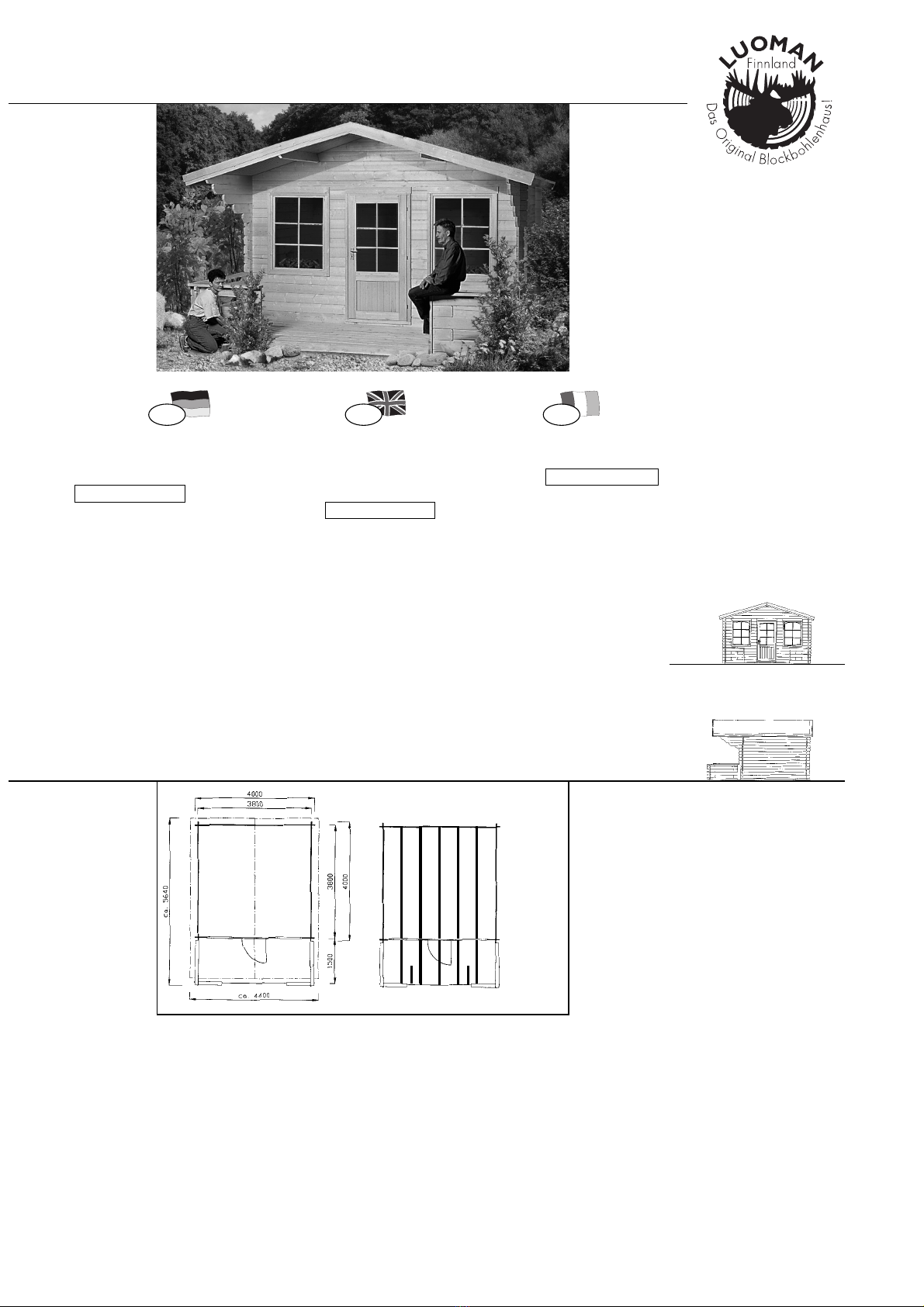
In der Übersichtszeichnung finden Sie die Maße
Ihres Hauses – so können Sie Ihr Fundament vor-
bereiten – die 7 Fundamentkanthölzer fürs
Gebäude (3,80m lang) werden längs angeord-
net, die 7 Stück T14, 1,50m lang folgen parallel
für die Terrasse, die 2 Stück T15, 0,50m lang unter-
stützen die Eckpfosten des Terrassengeländers und
die erste Diele am Eingang – Explosions-
zeichnung + Zeichnung 8 Terrasse.
1.
Lillevilla 50
Das A&O für die Stabilität, Funktion und
Haltbarkeit Ihres Hauses ist ein gutes
Fundament. Nur ein absolut waagerecht
ausnivelliertes und tragfähiges Fundament
(auch für die Terrasse) gewährleistet
einwandfreie Passung der Blockbohlen,
Türen, Fenster sowie gute Stabilität.
Flagstones or paving bricks on top of
a (frost-free) bed of gravel are suitable,
but frost-resisting concrete (either over
the whole area or in the form of piers)
is also ideal as a base for the floor-
joists (and is also good for ventilation).
After all, your "Lillevilla 50" is a "real" house.
In the general drawing you will find the dimensions
of your cabin – to allow you to prepare your foo-
tings – the 7 pedestal beams for the cabin (3.80 m
in length) are laid lengthwise; the 7 T4s, 1.50
m in length, follow parallel for the veranda, the 2
T15s, 0.50 m in length, support the corner posts
of the veranda's balustrade and the first floorboard
at the entrance. See close-up diagram and
diagram 8 showing the veranda.
The key to stability, functionality and
endurance is a good foundation for your
summer house. Only absolutely level,
strong footings (for the veranda as well)
ensure a perfect fit for the timbers,
the doors and the window while
guaranteeing stability.
Fondation
Vorsortierung Pre-sorting 2.
Trier
Des dalles de ciment ou des pavés com-
posites sur du gravier (antigel) sont pos-
sibles; L’idéal serait aussi (pour des raisons
d'aération) un béton résistant au gel – du
béton strié ou piqueté, sur lequel les
poutres de fondation sont posées et fixées
– car votre chalet "Lillevilla 50" est comme une
"vraie" maison. Le plan de disposition d'ensemble
vous donne les dimensions de votre chalet pour
préparer la fondation. Les 7 poutres de fondation
(3,80 m de long) pour le bâtiment sont disposées
dans le sens de la longueur. Les 7 pièces
T14, 1,50 m de long, suivent en parrallèle pour la
terrasse, les 2 pièces T15, 0,50 m de long,
soutiennent les piliers d’angles de la terrasse et la
première planche à l'entrée – Voir le schéma 2
+ schéma 8 Terrasse.
Pour être assuré d'avoir un chalet stable,
fonctionnel et durable, il convient d'avoir
une fondation solide. Seule une fondation
absolument plane, nivellée et solide (pour
la terrasse aussi) garantit que les madriers,
portes et fenêtres seront bien montés et que
la construction sera bien stable.
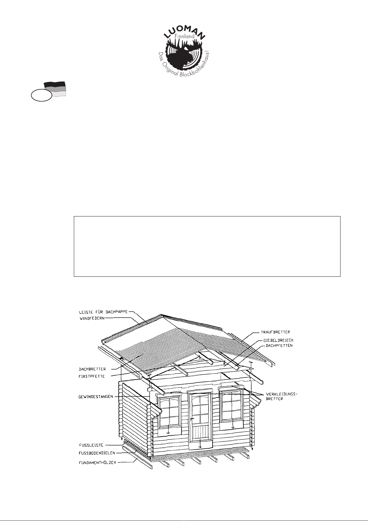
Hierzu bedienen Sie sich bitte der Explosions-
zeichnung und Zeichnung 1,die Ihnen alle
Teile der 4 Wände zeigt und Ihnen einen
Überblick über den gesamten Aufbau gibt –
die Terrasse vorab gesondert legen.Die ein-
gedruckten Bezeichnungen erlauben eine ein-
fache Prüfung und Zuordnung anhand der
Maße auf den Teilelisten – hier haben wir noch
einmal alle Teile mit Bemaßungen (ca.) auf-
geführt. Beachten Sie, daß die BOHLEN
der VORDER- und RÜCKWAND durch-
gehende BOHRUNGEN für’s Zuganker-
system haben – deswegen nicht mit den
SEITENWANDbohlen vermischen!
Lassen Sie sich bitte nicht durch die auf
den ersten Blick etwas verwirrende Vielzahl
von Teilen beim Öffnen des Bundes schrecken
– vorsortiert ist alles viel einfacher!
Pre-sorting - you don't need to worry about
the number of parts when you open the pack-
age – everything becomes much easier once
you have sorted the pieces into their
appropriate categories!
Prenez les schémas 1 + 2 qui montrent tou-
tes les pièces des 4 murs et donnent une vue
d'ensemble de la construction. Mettez de côté
ce qui concerne la terrasse. Les schémas vous
permettrons de procéder à la comparaison des
pièces et de les classer par dimensions – tou-
tes les pièces sont listées avec leurs dimensions
approximatives.
Attention: les madriers des murs AVANT
ET ARRIÈRE sont munis de TROUS
PERCÉS tout le long pour le dispositif
d'ancrage – ne les mélangez pas avec
les madriers des PAROIS LATERALES!
Ne vous laissez pas impressionner
par le nombre de pièces en ouvrant le
colis – Une fois trié et ordonné, tout
est plus facile!
5
111104
Please refer to the close-up diagram and dia-
gram 1 for assistance. This shows all the parts
belonging to the 4 walls and gives you a guide to
assembling the entire structure. Lay the parts for
the veranda separately to begin with. The refe-
rences on diagram 1 allow you to compare
them with the list of parts and allocate
them according to their dimensions – all the parts
are listed here once more, together with their appro-
ximate measurements. Please ensure that the
planks for the front and rear walls have
drill holes all along for the tension rod
system – for this reason, do not mingle
them with the planks for the side walls!
D GB F
2

Wandaufbau... Erecting the walls...
3.1
Lillevilla 50
Ordnen Sie die Teile, nach
kompletten Wänden sortiert, mit 1-2 m
Abstand (als Arbeitsraum) um das
Fundament an Zeichnung 2.
Before you start assembling the walls, lay the
7 treated floor-joists (3.80m) lengt-
hwise, and about the same distance
apart on top of the footings.
Even though the joists are Teknogrund®treated
it is a good idea to insert a layer of bituminous
felt or foil between the wall timbers and the
joists to prevent rising dampness.
Please see diagrams 1+8 for assembling the
walls and the veranda. First lock the bot-
tom wall planks (2 full-width wall
boards A1 and B1 for the front and
rear walls, and 2 half-width boards C1
for the side walls) together. Make sure
that the front plank A1 has been cut away
to allow the door to be fitted.
(A rubber mallet is of help everywhere in the
assembly process. To avoid damage, never
bang the timbers directly with the head
of the mallet – we have enclosed wooden
blocks (marked with an "X") to be placed on
the planks for protection purposes – the ends
of the timbers protruding at the corners require
particular care, to prevent the wood from
splitting). However, if they happen to split or
crack it has no negative constructional effects
and cracks can be glued later.
Please clean any splinters from the drill
holes to ensure that tongues and grooves and
the tension rods are a perfect fit!
Arrange all the parts for each wall on
either side of the foundations, leaving
1–2 m working space. See diagram 2.
Montage des murs...
Avant de commencer à monter les murs, posez
sur votre fondation les 7 poutres
traitées de 3,80 m à intervalles régu-
liers dans le sens longitudinal.
Les poutres sont traitées avec un produit appelé
Teknogrund®, pourtant il est recommandé par
sécurité de mettre une couche de feuille bitumée
entre les madriers et les poutres de fondation
pour empêcher que l'humidité ne remonte.
Pour le montage des murs et de la terrasse,
reportez-vous au schéma 1+8. Assemblez
d'abord les madriers inférieurs (2 mad-
riers A1 et B1 entiers pour les murs
avant et arrière ainsi que 2 demi-mad-
riers C1 pour les murs latéraux).
Attention: le madrier avant A1 a une décou-
pe pour la porte.
Pour tout le montage, utilisez un maillet en caou-
tchouc. Ne tapez jamais directement sur
les languettes pour éviter de les endomma-
ger – Nous avons joint à la livraison des cales
de bois (marquage "X") que vous intercalerez
pour éviter les marques du maillet. Faites atten-
tion aussi aux extrêmités et angles des madriers
pour éviter que le bois ne se fende!
Enlevez les débris des perçages pour que les
madriers s'adaptent parfaitement aux rainures
+ languettes ainsi qu'à l'ancrage!
Cherchez les pièces qui forment
un mur complet et disposez-les
à 1-2 m autour de la fondation.
Voir schéma 2.
Diese erste Bohlenlage in den Eckfügungen auf
den Fundamentbalken verschrauben oder ver-
nageln (vorbohren!) Zeichnung 4.
Screw or nail this first row of timbers at the
corner joints (drilling the holes first!). See
diagram 4.
This "frame" shows the size of the cabin,
to make it easier to space the joists the
same angle – at this stage it is important
to make sure that the walls are exactly at
right angles to each other!
Fixez à l'aide des vis et clous (en ayant
préalablement percé des trous!) ce premier
étage de madriers dans les encoignures sur les
poutres de fondation. Voir schéma 4.
Ce "cadre" vous donne une idée de la
grandeur du chalet et il est plus facile de
placer avec exactitude les poutres de
fondation – Faites attention que les angles
des murs soient bien à angle droit!
6111104
D GB F
Bevor Sie mit dem Wandaufbau beginnen,
legen Sie die 7Stück imprägnierte
Fundamentbalken (3,80m) in etwa glei-
chen Abständen zueinander längs auf
Ihr Fundament.
Die Balken sind zwar imprägniert, Sie sollten
aber dennoch zur Sicherheit eine Lage Bitumen-
pappe oder Folie zwischen Wandbohlen und
Fundamentbalken legen, um das Aufsteigen
von Feuchtigkeit zu verhindern.
Den Aufbau der Wände und der Terrasse ent-
nehmen Sie bitte der Zeichnung 1+8.
Stecken Sie zuerst die unteren Wand-
bohlen (2 ganze Wandbohlen A1 und
B1 für Vorder- und Rückwand sowie 2
halbe Bohlen C1 für die Seitenwände)
zusammen. Beachten Sie, daß die Vorder-
wandbohle A1 einen Ausschnitt für die
Tür hat.
Hier hilft, wie bei der gesamten Montage, der
Einsatz eines Gummihammers. Schlagen Sie
jedoch nie direkt auf die Feder, um
Beschädigungen zu vermeiden – wir haben
Ihnen Holzklötzchen (mit ‘X’ markiert) mitge-
liefert, die Sie bitte auf die Feder stecken, um
so einen Schlagschutz zu erhalten – auch die
über die Ecken hinausstehenden Bohlenenden
erfordern besonders sorgfältige Arbeit, um ein
Absplittern zu vermeiden. Sollten die Enden
doch einmal absplittern, so können Sie diese
leicht am fertigen Gebäude mit etwas Leim auf-
stecken – dies hat keine konstruktiven Nachteile.
Bitte reinigen Sie die Bohrungen von
Splittern für einwandfreie Passung der Bohlen
in Nut + Feder sowie der Zuganker!
Dieser ‘Rahmen’ gibt Ihnen die Größe
des Hauses vor und so können Sie die
Fundamentbalken leicht exakt ausrichten
– hierbei unbedingt auf Rechtwinkligkeit
der Wände achten!

Dies ergibt eine Tropfkante und schützt vor
Nässe – auf jeden Fall aber auf eine ausrei-
chende Kante nach innen als Auflage
der Fußbodendielen achten Zeichnung 3.
Lillevilla 50
Und noch etwas: Die Seitenwände
sollten 3-4 mm über die
Fundamentbalken überstehen:
- this forms an overhang and keeps dampness
at bay – make absolutely certain that there is
an adequate ledge on the inside to
take the floorboards. See diagram 3.
Another point: the side walls ought to
protrude 3–4 mm over the floor-joists:
Ce rebord joue le rôle de gouttière et protège
de l'humidité – faites attention à ce qu'il y ait
un dépassement suffisant vers l'intérieur
pour servir d'appui au plancher.
Voir schéma 3.
A noter: les murs latéraux
devraient dépasser de 3 à 4 mm les
poutres de fondation;
7
111104
D GB F
... + Tür + Fenster ...+ door + window
Bereits jetzt schieben Sie die komplett
mit Rahmen montierte Tür vorsichtig
(ohne zu Verkanten, deswegen die
Wände nicht höher bauen...) in den
Wandausschnitt hinein.
Die Schwelle des Türrahmens soll unten fest
zum Aufliegen kommen.
Richten Sie den Rahmen der Tür (und somit die
ganze Tür) schon jetzt waagerecht und recht-
winklig durch leichte Schläge mit dem
Gummihammer aus (bitte ein Schlagholz unbe-
dingt dazwischen legen) und prüfen Sie nach
Montage der Türgriffe die Gängigkeit.
Die Wände werden weitergebaut bis
zur 5. Vorderwandbohle – jetzt mit den
kürzeren Bohlen A3 / A4 weiterbauen und
bereits nach 2 Bohlen die fertig im Rahmen
montierten Fenster vorsichtig einschieben.
Fenster + Türrahmen nicht an den
Wandbohlen befestigen.
Bauen Sie nun nach der Zeichnung 1
die Wände Bohlenlage um Bohlenlage
bis zur 3. oder 4. Vorderwandbohle
weiter hoch.
At this point, the door – complete with
door frame – has to be inserted
carefully in the space provided (avoid
jamming it, which is why the walls
must not be any higher …).
The bottom of the doorsill should be absolutely
level with the base.
Now adjust the door frame (and accordingly
the whole door), by gently tapping it with the
rubber mallet (using wooden blocks), until it is
level and squarely placed. Once the door hand-
les have been fitted, check to see whether the
door can be opened and closed easily.
The walls are assembled up to the 5th
front timber – now continue with the shorter
planks A3/A4 and 2 planks later carefully ins-
ert the ready-assembled windows in their frames.
Note! Please make sure to install the window
hinges up. Also remember that the window
may fall off the hinges if opened too much.
Window and door frame should not be
fixed to the wall planks.
Continue erecting the walls, one layer of
planks at a time, according to diagram 1
until the 3rd or 4th front timber
has been reached.
...porte + fenêtre
Maintenant installez la porte complète
avec son cadre (sans forcer, c'est pour-
quoi les murs ne doivent pas être
montés plus hauts...) dans la découpe
prévue à cet effet.
Il ne doit pas y avoir de jour sous le seuil du
cadre porte.
Contrôlez, en vous servant du maillet (ne pas
oublier la cale de montage), que le cadre de
la porte (donc toute la porte) soit bien à niveau
et d’équerre, montez les poignées puis assu-
rez-vous que la porte s'ouvre et se ferme sans
frottement.
Continuez à monter les murs avant jus-
qu'au 5ème madrier – Continuez ensuite
avec les madriers plus courts A3/A4 puis
après 2 madriers, insérez en faisant atten-
tion les fenêtres prémontées.
Attention! Veiller à installer les gonds de la
fenêtre dans le bon sens et s'assurer que l'ou-
verture n'est pas trop grande afin que la fenêtre
ne sorte pas de ses gonds.
Ne fixez pas la fenêtre et le cadre de
la porte sur les madriers.
Continuez à monter les parois selon le
schéma 1 jusqu'à ce que le 3ème ou 4ème
madrier de la paroi avant soit en place.
...Wandaufbau... Erecting the walls... Montage des murs...
34
3.2

...Wandaufbau ...Erecting the walls
Die Vorderwand wird durch die Bohle A5
geschlossen (3 Aussparungen für Fenster und
Tür).
Abschließend die Giebel vorsichtig auf-
setzen um ein Absplittern der Bohlenenden
zu vermeiden. Giebel vor Herabfallen sichern!
3.3
Lillevilla 50
Beachten Sie,
daß das Vordach mit den stufenförmig
länger werdenden Bohlen C 3, C4, C5,
C6, C7 gestützt wird, deswegen hier beim
Seitenwandaufbau besonders die
Zeichnung 1 beachten!
The front wall is completed using the plank A5,
which has 3 openings for the windows and the
door.
Finally, mount the gable carefully to
prevent the ends from splintering.
MAKE SURE
that the roof overhang is supported by the
planks C3, C4, C5, C6, C7 – which get
progressively longer – so pay special
attention to diagram 1 for
the construction of the side walls.
...Montage des murs
Außerdem! Moreover!
3.4N'oubliez pas!
Le mur avant se termine en posant le madrier
A5 qui a trois découpes pour la porte et les
fenêtres.
Installez ensuite les pignons en faisant très
attention de ne pas fendre les extrêmités.
Dann die Wände weiterbauen und auch,
wie bei der Tür, die Fenster im Rahmen schon
jetzt gängig ausrichten.
Continue erecting the walls, adjusting the
windows at this point, in the same way as the
door, to make sure they open and close properly.
Continuez à monter les murs et, tout
comme pour la porte, ajuster les fenêtres et véri-
fier qu'elles s'ouvrent et se ferment sans frotte-
ment.
FAITES ATTENTION
à ce que l'auvent soit soutenu par les
madriers C3, C4, C5, C6 et C7 par ordre
croissant. Pour le montage des murs,
suivez donc bien le schéma 1!
Ferner werden Sie bemerken, daß ein
Spalt (Ausgleichsspielraum) über der
Tür und den Fenstern bleibt.
Dieser Spalt ist sehr wichtig für eine
Blockhauskonstruktion – Ihr Blockhaus wird
sich im Laufe der Jahreszeiten und unterschied-
lichen Witterungen immer etwas ‘setzen’ (bis zu
3-4 cm) – hierzu muß dieser ‘Ausgleich-
spielraum’ über den Elementen frei blei-
ben, sonst ‘hebt sich das Haus geradezu aus-
einander’ – bei nasser Witterung wiederum quellen
die Bohlen etwas – dieser Schlitz wird abschließend
mit Abdeckbrettchen verdeckt, die am Rahmen
(nicht an den Bohlen!) befestigt werden, um
das ‘Arbeiten’ nicht zu behindern – aus diesem
Grunde sollten Sie auch z.B. beim Einbau von
Regalen beachten, die Träger nicht an mehreren
Wandbohlen übereinander zu verschrauben! Bei
den Fenstern werden die langen Abdeckbrettchen
(1010mm) außen angebracht; die Kurzen (980mm) innen.
Ferner werden Sie feststellen,
daß die Wände mehr oder weniger stark
beim Aufbau nach oben ‘auseinanderstre-
ben’ – auch dies ist konstruktionsbedingt
und nicht weiter schlimm, da die
Konstruktion nach oben dann ja durch
die fertig montierten Giebel, sowie
durch die Pfetten und die Dachfläche
geschlossen wird und das Zugankersystem
endgültige Stabilität garantiert.
You will also notice that there is still a
gap (compensatory allowance) over
the door and the window.
This gap is very important for a log
cabin structure – your summer house will
"settle" (up to 3–4 cm) during the course of the
different seasons and varying weather
conditions. To allow for this, there has to be
some allowance above these fittings,
otherwise the house will "lift itself apart". When
the weather is wet, on the other hand, the woo-
den planks swells slightly – this gap is covered
on the interior and the exterior by the enclosed
facing panels, which are fixed to the frame (not
to the timbers!), so as not to hinder the wood's
"activity". For this reason, you should also be
careful, for example, when putting up shelves,
that the brackets are not screwed to several
timbers, one above the other!
You will notice that the walls tend to lean
outwards towards the top, when being
erected - this is to be expected. The
structure is secured at the top by means
of the ready-assembled gables, the purlins
and the roof-boards, which ties the
structure together.
Vous remarquez aussi qu'il reste un
interstice (un jeu de compensation) au
dessus de la porte et des fenêtres.
Cet interstice est très important pour la
construction d'un chalet en madriers –
en effet, au fil des saisons et des intempéries,
elle aura tendance à "se tasser" (jusqu'à 3 ou
4 cm) – cet espace libre au-dessus de la
porte et de la fenêtre doit rester, sinon
le chalet risque de "se soulever" – par temps
pluvieux p.ex. les madriers gonflent un peu.
Cette fente est ensuite masquée en apposant
des couvre-joints fixés sur le cadre (et non sur
les madriers) pour laisser le bois travailler. Pour
cette même raison, si vous montez p. ex. des
tagères, faites attention à ne pas fixer un même
support sur plusieurs madriers!
En montant les murs, vous constaterez
qu'ils ont tendance à "remonter" – ceci
une caractéistique de la construction et
n'a rien d'alarmant puisque cette
construction sera achevée en haut par
les pignons prémontés, les pannes et la
toiture et que le dispositif d'ancrage lui
conférera la stabilité définitive.
8111104
D GB F

Wichtig! Important!
Wie gesagt, ist es bei dem reinen Naturmaterial
Holz auch bei sorgfältigster Bearbeitung tech-
nisch nicht möglich, 100% ‘totes’ Material zu
produzieren:
Durch die ständig wechselnden Temperaturen
und Luftfeuchtigkeiten übers Jahr, verbunden
mit Regen, Wind und Sonne wird Holz immer
etwas ‘arbeiten’, dies ist bedingt durch das
Quellen und Trocknen der Holzzellen.
Hier können sich auch die Bohlen
immer etwas verdrehen – auch dies
hat, wenn sie (auch mit Anstrengung)
zusammenzufügen sind, keinen Einfluß
auf Stabilität und Funktion der
Konstruktion. Auch ist leichter, wech-
selnder Verzug des Massivholz Tür-
blattes nie ganz zu vermeiden – eine
100%ige Passung kann bei Massivholz
nicht gewährleistet werden.
Das Quellen und Trocknen der Holzzellen
bewirkt auch das beschriebene ‘Sacken’ der
Wände – deshalb wird die fertig im Rahmen
montierte Tür und auch die Fenster lose in die
Wand eingesetzt – nur so kann das Holz ‘arbei-
ten’ ohne daß die Konstruktion Schaden neh-
men könnte.
Dies wird sich nach einer Saison Sommer /
Winter so einpendeln, daß Sie dann auch bei
Bedarf die Rahmen mit den unteren Wand-
bohlen an zwei, drei Punkten leicht verschrau-
ben können.
Allerdings läßt es sich leider nicht umgehen,
daß Sie, besonders in der Anfangszeit und bei
extremer Witterungsfolge, die Gängigkeit der
Tür und auch der Fenster regelmäßig prüfen
und nachstellen.
Dies sollte durch Ausrichten des kompletten
Rahmens durch leichte Schläge mit dem
Gummihammer erfolgen (Schlagholz dazwi-
schen legen, bitte) oder auch durch herein- und
herausschrauben der Scharnierbänder.
Lillevilla 50
Noch ein paar Worte zum Holz sowie der
Passung der Tür und der Fenster:
As we have already mentioned, it is technically
impossible to produce absolutely inert material
in the case of wood, even with the most sophi-
sticated production methods, since it is a purely
natural material.
Due to the constantly changing temperatures
and air moisture content during the course of
the year, combined with rain, wind and sun-
shine, wood will always shrink and swell
alternately, as the pores absorb moisture and
dry out again.
It is possible that the timbers may warp
a little, but this has no influence on the
structure, nor can a slight warping of
the solid wood door be avoided
altogether.
The swelling and drying of the pores in the
wood also leads to the "sinking" of the walls
described above – this is why the door and
the windows in their respective frames are
inserted loosely in the walls – this being the
best way to ensure that the wood's "activity"
does not cause any damage to the structure.
As a general rule, this phenomenon will level
out after one summer/winter season, so you
can then screw the frames to the lowest wall
timber at two or three points if you wish to.
However, there is no way of avoiding the
necessity of checking. You should in any case
check the door and the windows at regular
intervals, especially at the beginning and
under extreme weather conditions, and adju-
sting them as required.
This should be done by adjusting the whole
frame using gentle taps of the rubber mallet
(please use wooden blocks in between) or
by tightening or loosening the hinges.
A few words about wood and fitting the
door and the windows:
Important!
Comme nous l'avons déjà précisé, le bois est
un matériau naturel.
Les variations permanentes des températures
et des degrés d'humidité au cours de l'année,
auxquelles s'ajoutent la pluie, le vent et le soleil,
font que le bois "travaille´" toujours un peu, ce
qui a pour effet un gonflage et une rétraction
des cellules du bois.
Les madriers peuvent donc se déformer
– mais, même si on doit forcer pour les
assembler, cela n'a aucune influence
sur la stabilité et leur fonction dans la
construction. De même, il est probable
que la porte en bois massif se déforme
légèrement.
Le gonflage et le séchage des cellules de bois
font que les murs "se tassent". C'est pourquoi
la porte prémontée dans son cadre et aussi
les fenêtres sont assemblées sans fixation
dans les murs – pour que le bois puisse "tra-
vailler" sans endommager la construction.
Une saison passée été/hiver, la situation va
se régulariser et si nécessaire vous pourrez
mettre deux ou trois vis dans les cadres et
madriers inférieurs.
A noter aussi qu'il est inévitable que, surtout
dans les premiers temps et en cas d’ intempé-
ries, vous deviez régulièrement contrôler et
réajuster la porte et les fenêtres.
Pour ce faire, tapez légèrement sur tout le
cadre avec un maillet (veuillez utiliser la cale
de bois) ou encore en serrant et desserrant
les vis des charnières.
Remarques sur le bois et l'ajustement
de la porte et des fenêtres:
9
111104
D GB F
4.

3
Fussboden Floor
5.
Lillevilla 50
Die Fußbodendielen haben Nut
und Feder – die Unterseite erkennen Sie
an den Fasen und 2 Trockennuten.
Please note that, in the same way as the
profiled boards for the roofing, the back
of floorboards may show some une-
venness caused by the planer, which is
quite normal in the timber manufactu-
ring process and no real defect.
Begin laying the floorboards at the front wall
– the groove of the first board to the wall.
Make sure that they lie flat on the joists of
the sidewalls. See diagram 3.
Continue laying the boards, one after the other,
finishing with the plain-edged final board.
Here, the same applies with regard to the natu-
ral warping of the wood (particularly since it
is close to the dampness of the ground), so that
a perfect fit cannot be guaranteed. Please make
sure that the floorboards are not laid too clo-
sely together – this can be achieved by adju-
sting the tongues and grooves of the last 5–10
boards to allow the wood to swell in damp wea-
ther and close the surface, without the risk of
the floor arching upwards, as might happen if
the boards were a tight fit.
Once the surface has been covered evenly, the
floorboards are nailed securely to the floor-joists
and the skirting boards fixed all the way round.
TThe skirting board is an attractive way
of finishing off the wall/floor junction.
The floorboards are tongued and
grooved – the underside is recognisable
because of its chamfers and 2 dry grooves.
Plancher
Notez qu'ici, tout comme pour les plan-
ches de la toiture, le dessous du bois
peut présenter des marques de rabot
ou des flaches. Les raisons sont d'or-
dre purement technique et ne saurai-
ent faire l'objet d'une réclamation.
Commencez par poser les madriers de la paroi
avant – la rainure de la première lame contre
le côté mur. Assurez-vous que la lame repose
bien sur les poutres de fondation des parois
latérales. Voir schéma 3.
Posez les lames une par une et terminez par la
lame ayant les rainures des deux côtés.
Ici aussi, un ajustement parfait et définitif ne
peut avoir lieu du fait que le bois travaille
(surtout sur un sol humide). Ne serrez donc pas
trop les lames – notamment les 5-10 dernières
lames pour que le bois puisse travailler par
temps humide, qu'il puisse se distendre et éviter
ainsi que le plancher ne gondole.
Quand le plancher sera uniformément fermé,
clouez les lames sur les poutres de fondation
puis posez les plinthes tout autour.
Les plinthes ont aussi pour but de
cacher les éventuelles irrégularités et
interstices des murs.
Les lames de plancher ont des rainures et
languettes – vous reconnaissez le dessous
aux biseau et 2 rainures.
10 111104
D GB F
Beachten Sie bitte hier, wie auch bei
den Profilbrettern der Dacheindeckung,
daß auf der Rückseite aus produk-
tionstechnischen Gründen Hobelfehler
sowie Baumkante erlaubt sind und
keinen Reklamationsgrund darstellen.
Beginnen Sie beim Verlegen an der Vorder-
wand – die Nut des ersten Brettes zeigt zur
Wand. Beachten Sie hier, daß eine gute
Auflage auf den Fundamentkanthölzern der
Seitenwände gewährleistet ist Zeichnung 3.
Diele für Diele weiterverlegen. Dielenfläche in
Nut und Feder ausgleichen und mit der paral-
lel besäumten Enddiele schließen.
Auch hier gilt, daß durch das natürliche
Arbeiten des Holzes (gerade im feuchten
Bodenbereich) eine 100%ige Passung nicht
gewährleistet werden kann. Es sollte darauf
geachtet werden, daß die Dielen nicht zu
stramm ineinander verarbeitet werden – dies
erreichen Sie durch Ausgleichen der letzten
8 - 10 Dielen in Nut und Feder, so kann das
Holz bei Feuchtigkeit ‘arbeiten‘ und die Fläche
geschlossen werden, ohne daß die Gefahr
besteht, daß sich die Bodenfläche bei zu stram-
mer Verlegung wölben könnte.
Ist die Fläche gut ausgeglichen geschlossen,
werden die Dielen mit den Fundamentbalken
vernagelt und anschließend die Fußleisten
umlaufend angebracht.
Die Fußleisten helfen auch, gegebe-
nenfalls aufgetretene Unregelmäßig-
keiten und Spalte an den Wänden zu
verdecken.

Dachfläche...
Nun noch einmal die Rechtwinkligkeit der
gesamten Konstruktion sowie die Gängigkeit
der Tür und die Flucht der Giebel mit der Vorder-
und Rückwand prüfen – ist dies ok, kann mit
der Dacheindeckung begonnen werden.
Hierzu werden die Softlineprofilbretter (Profil
nach innen, Rückseite, erkenntlich an der
einen Trockennut, nach außen) verwendet.
Auch hier sind Hobelausläufe, Baum-
kante etc. auch in den Nuten und
Federn produktionstechnisch bedingt
und kein Reklamationsgrund.
Beginnen Sie mit 2 Profilbrettern, Nut
nach außen zeigend, an der Außen-
kante der Pfetten / obere Dachkante C7;
es folgen die weiteren Profilbretter, flächig
verlegt (nicht zu stramm) – Zeichnung 5.
Achten Sie beim ganzen Dach auf
Parallelität der Traufkanten und gleich-
bleibenden Überstand über die Wände
sowie gleichmäßiger und stabiler
Auflage auf den Pfetten. Alle Profilbretter
gut und fest an Wänden, Giebel und Pfetten
vernageln – die letzten Bretter besäumen Sie
bitte (z.B. mit einer Stichsäge), so daß Sie einen
bündigen Abschluß an der Außenkante Pfetten
/ Dachkante erhalten.
Die gute und stabile Befestigung der
Dachfläche ist wichtig für die Gesamt-
stabilität des Hauses!
Arbeiten Sie sicher! – Die Dachfläche
ist nicht begehbar!
Lillevilla 50
Bevor Sie beginnen, stecken Sie bitte die
Zuganker (4 Gewindestangen)
bündig mit der Giebelfläche durch die
Wandbohrungen! Es geht weiter mit
dem Einsetzen der Firstpfette in die
Ausschnitte der Giebel – diese erkennen
Sie am dachförmigen Profil – es folgen die
weiteren 2 Pfetten, die alle bündig mit
der Giebelfläche eingesetzt werden.
Now check again that the whole structure is
perfectly square, that the door can be opened
and closed properly and that the gable follows
the lines of the front and back wall – if all this
is all right, work can commence on the roof.
Use the softline-profiled boards, with the soft-
line-profile on the inside and the back side
(recongized by one dry groove) on outside, for
this task. Here again, any unevenness
caused by the planer, rough edges etc.
even in the grooves and tongues, are
due to well-tried production techniques
and quite normal.
Begin with the 2 profiled boards, with
the groove pointing outwards, on the
outer edge of the purlins/the top edge
of the roof C7; followed by the other
profiled boards, to form a firm surface (not
too tight) – diagram 5. It is advisable to leave
a space of 1 – 1,5 mm between the
boards because the wood shrinks and expands
according to the weather.
The entire roof should be checked for
parallel eaves, a uniform overhang
over the walls and an even, firm sup-
port in the case of the purlins. All the pro-
filed boards should be nailed securely to the
walls, gables and purlins – please trim the last
boards (for example, using a fretsaw) for a flush
edging on the outer rim of the purlin/roof edge.
A firm, durable anchoring of the roof
is important for the stability of the
cabin as a whole! Take care when you
work! – The roof is not intended for
standing on!
Before you begin, insert the tension rods
(4 threaded rods) flush with the gable
surface through the holes drilled in the
walls! Continue by inserting the
ridge purlin into the cut-out gable
sections –recognisable by their slanting
profile – followed by the 2 other purlins,
which are all put into position flush
with the gable surface.
Toiture
Contrôlez maintenant que toute la construction
soit à angle droit, que la porte s'ouvre et se
ferme correctement, que le pignon soit bien ali-
gné avec les murs avant et arrière – si tel est
le cas, commencez les travaux de couverture
de la toiture.
Pour cela, utilisez les voliges profilées, le pro-
fil softline vers l'intérieur et l'envers avec une
rainure vers l'extérieur. Ici aussi, les traces
de rabot, les flaches, etc. même dans
les rainures et languettes sont dues à
des raisons techniques et ne peuvent
faire l'objet d'une réclamation.
Commencez par poser 2 voliges (rainu-
res vers l'extérieur) sur le bord
extérieur des pannes / bord supérieur
du madrier C7; posez ensuite les autres
voliges, sans trop les serrer – Voir schéma 5.
Toujours parce que le bois "bouge" en fon-
ction de l'humidité, il est bon de laisser un
jeu de 1 – 1,5 mm entre les voliges.
Pour l'ensemble de la toiture, faites atten-
tion à ce que les bords des planches de
rive soient parallèles, que l'avancée soit
régulière et que la pose soit solide sur les
pannes. Clouez les voliges pour les fixer défi-
nitivement aux murs, pignon et pannes – Sciez
les dernières planches (p. ex. avec une scie sau-
teuse), pour obtenir un bord à bord avec le bord
extérieur pannes/bord de la toiture.
Toute la stabilité du chalet repose sur
une toiture montée parfaitement!
Pensez à votre sécurité!
Ne marchez pas sur le toit!
Avant de commencer, passez les 4 tiges
filetées servant d'ancrage dans les trous
percés des madriers et mettez-les bord à
bord avec les pignons. Continuez ensuite
en montant la panne faîtière dans les
encoches des pignons – vous la reconnais-
sez à son profil rappelant la forme du toit
– posez ensuite les 2 pannes suivantes
bord à bord avec la surface du pignon.
11
111104
D GB F
6.1
5
Roofing
Anfang
Start
Début
Abschluss
Finish
Fin
Sägen
sawing direction
Scier

Nun folgen die schmalen Traufkantenbretter
C9, die Sie bündig mit der Dachfläche verna-
geln - auch hier hilft Ihnen die Zeichnung 6b.
Es folgen die breiten Windfedern A7, die Sie
bündig mit der Dachfläche befestigen. Nun kön-
nen Sie bereits mit der Dachpappeindeckung
beginnen.
Schneiden Sie die Bahnen in Dachlänge exakt
rechtwinklig zu und beginnen Sie genau par-
allel zur Traufkante mit der Verlegung – hierbei
unbedingt einen Überstand von 2 - 3 cm als
Tropfkante belassen – dies schützt die
Dachbretter am besten vor Feuchtigkeit
Zeichnung 6c. Die folgenden Bahnen wer-
den von oben einige cm überlappend vernagelt.
Schließlich werden die Enden der Dach-
pappbahnen mit den Leisten A9 hinter den
Windfedern befestigt Zeichnung 6b + 6c.
6.2
Lillevilla 50
Befestigen Sie nun die breiten Traufkanten-
bretter C8 bündig mit der Traufkkante
unter der Dachfläche. Zeichnung 6b.
Now it is the turn of the narrow fascia boards
C9, which you nail flush to the roof – diagram
6b can assist you here as well. Then mount the
wide wind shields A7 – they should be fixed
flush to the roof. Then work can begin on the
roofing fabric.
Cut sheets the length of the roof with exactly
90° corners and start laying the roofing felt par-
allel to the eaves – be sure to allow an over-
hang of 2–3 cm – this is the best way of
protecting the roof planks from dampness. See
diagram 6c. Start at the eaves and finish with
a strip along the apex.
Finally, the ends of the lengths of roofing fabric
are fixed behind the wind shields using the
strips A9. Diagrams 6b + 6c.
Attach the wide fascia boards C8
flush with the eaves beneath
the roof – diagram 6b.
Viennent ensuite les planches de rive C9, à
clouer bord à bord avec la toiture. – Reportez-
vous au schéma 6b. Posez ensuite les plan-
ches de corniche A7, à fixer bord à bord avec
la toiture. Commencez ensuite à poser le feutre
bitumé.
Découpez des bandes à angle droit et posez-
les parallèlement à la planche de rive en
laissant dépasser de 2 à 3 cm pour empêcher
l'humidité de pénétrer. Voir schéma 6c. Posez
les autres bandes en les superposant en haut
de quelques cm puis clouez-les.
Pour terminer, fixez les extrêmités des bandes
de feutre bitumé à l'aide des baguettes A9 der-
rière les planches de corniche. Voir schéma
6b + 6c.
Fixez maintenant les planches de rives C8
bord à bord avec le rebord gouttière sous
la toiture. Voir schéma 6b.
Sie können diesen Ortgang aber auch
individuell auf verschiedene Weisen
ausführen, z. B. indem Sie diese Leisten
unter die Pappe hinter den Windfedern
befestigen und die Dachpappe dann über
die Windfedern führen - Sie sollten nur
vermeiden, daß Wasser die Dachfläche
dauerhaft angreift und so zu Schäden
führen kann.
Die schmalen Windfedern A8 werden, je
nach Ausführung des Ortganges, in beliebi-
ger Höhe zur Zierde vorgesetzt.
You can perform this task even more
individually in different ways, for
instance, by fixing these strips under the
roofing fabric behind the wind shields
and then pulling the roofing fabric over
the wind shields. It is in any case
important to avoid water penetrating the
roof and causing permanent damage.
The narrow wind shields A8 can be moun-
ted at any height for decoration, depending
on the specification of the task.
Vous pouvez aussi choisir de réaliser cet
avant-toit de diverses manières :
p. ex. fixez ces baguettes sous le feutre
bitumé derrière les planches de corniche
puis faites passer le feutre bitumé sur les
planches de corniche. Vous devez seule-
ment empêcher que l'eau pénétre la
toiture ce qui causerait des dommages.
Les planches de corniche plus étroites A8
seront appliquées, en fonction du modèle de
l'avant-toit, à la hauteur souhaitée et serviront
de décoration.
12 111104
...Toiture...Dachfläche ...Roofing
6b
C9 C8
A9
A7
A8
A9 Traufkante ca.
2cm Überstand
eaves – approx.
2 cm overhang
Rebord dépassant
d'env. 2 cm
6c
A7 A8
D GB F

Sturmsicherung Protection against gales
Um die Sturmsicherheit des Hauses zu gewähr-
leisten, verfügt Ihr ‚Lillevilla 50‘ über das
Zugankersystem – dies ist sicherlich die
hochwertigste und stabilste Lösung, die im
Bereich Blockbohlenhäuser möglich ist.
Um diese Sicherheit immer voll zu gewährlei-
sten, ziehen Sie bitte regelmäßig die Muttern
der Zuganker leicht und ohne Gewalt nach
– in den feuchten Jahreszeiten wird das Holz
ggfs. etwas quellen – dann bitte die
Muttern etwas lockern – so können sich
die Wände wieder ‚einspielen‘, ohne von den
Gewindestangen behindert zu werden.
Durch das beschriebene ‚Sacken‘ kann es sein,
daß die Gewindestangen auf dem Boden auf-
stoßen und durch Herausdrücken nach oben das
Dach beschädigen können – dann einfach die
Stangen mit einer Eisensäge entsprechend kür-
zen, damit sie nicht auf dem Boden aufliegen
Zeichnung 7.
Lillevilla 50
Ihr 45 mm Haus ist extrem
stabil – keine Frage, dennoch sind die
Zugkräfte und Belastungen durch
Windböen bei einem Haus sehr stark.
To enhance the gale resistance of your summer
house, the "Lillevilla 50" is equipped with a
tension rod system. This is probably the best
and most stable solution that can be provided
for log cabins.
To ensure this safety to the full at all times, you
should regularly tighten the nuts of the tension
rods, gently and without force – in the damp
months the wood is likely to swell – then
loosen the nuts a little. This allows the walls
to "readjust" without being hindered by the
threaded rods.
In view of the "sinking" described above, it is
possible that the threaded rods touch the gro-
und and could damage the roof when pushed
upwards. Then simply saw a piece off the end
with a metal saw, so that they do not rest on
the ground any more. Diagram 7.
Your 45 mm log cabin isis extremely solid
and stable – there is no doubt about that,
but the burden on any house caused by
the force of gales must be considered.
Stabilité au vent
Pour assurer votre chalet "Lillevilla 50" face au
vent et à la tempête, elle dispose d'un
dispositif d'ancrage – la solution la plus
élaborée et la plus sûre applicable aux chalets
en madriers.
Pour conserver cette résistance au vent,
resserrez légèrement et sans force
régulièrement les écrous du dispositif d'ancrage
– par temps humide, le bois a tendance à
gondoler – desserrez alors les écrous –
pour que les parois puissent se distendre sans
que les tiges filetées les gênent.
Du fait que la construction a tendance à "se
tasser", il peut arriver que les tiges filetées
touchent le sol et en dépassant par en haut
endommagent le toit. Dans ce cas, raccourcissez
simplement les tiges filetées à l'aide d'une scie
à métaux pour qu'elles ne gênent plus. Voir
schéma 7.
Votre chalet de 45 mm est extrêmement
stable – cela ne fait aucun doute. Pourtant
la force des courants d'air et les actions
du vent peuvent être importantes pour
un chalet.
13
111104
D GB F
7.
7
Gewindestangen
threaded rods
tiges filetées
Unterlegscheibe + Mutter
washer and nut
Rondelle + écrou
Unterlegscheibe + Mutter
washer and nut
Rondelle + écrou
Gewindestangen
threaded rods
tiges filetées

Anbau der Terrasse Erecting the veranda
Die 2 kurzen Fundamenthölzer T15
werden unter die Eckpfosten des Terrassen-
eingangs und als Auflage für die erste
Terrassendiele eingebaut.
Die 2 Halbbohlen T5 werden auf die äuße-
ren Lagerhölzer aufgelegt – bitte auch hier
einen leichten Überstand als Tropfkante berück-
sichtigen und auf genügend Auflagefläche nach
innen für den Terrassenbelag achten. Nun die
Fußbodendielen T16 mit gleichem Abstand
(‘Schlitz’ ca. 1cm) zueinander auslegen und
vor dem Vernageln (die erste Diele am Haus
muß geschraubt werden) ausrichten, um glei-
che Abstände zu gewährleisten; die kürzere
Diele T17 wird als Abschluß leicht vor-
stehend zwischen die Eckpfosten ein-
gebaut – achten Sie bitte hierbei auf gute und
sichere Auflage der Diele auf den Fundament-
kanthölzern (T15).
Hier die erste Diele am Haus bitte ab-
nehmbar anschrauben, um einwand-
freien Zugang zu den Muttern der
Zuganker zum Nachziehen zu gewähr-
leisten.
Die Eckpfosten werden zusätzlich mit den
Metallwinkeln auf der Bodenfläche verschraubt
– es folgen die Terrassensitzbretter T10 +
T9 sowie die beiden U-Profilleisten T11
als Abschluß rechts und links des
Eingangs.
Abschließend wird das Terrassengeländer
mit den Brettern T12 am Haus befestigt. Das
verbliebene Glattkantbrett T18 wird als opti-
sche Abdeckung vor die Fundamentbalken gena-
gelt – beachten Sie jedoch bitte immer, daß gute
Belüftung der gesamten Unterkonstruktion
gewährleistet ist – immer noch der beste Schutz
vor Fäulnis (dennoch sind die Dielen Ihres
Hauses optimal imprägniert und aus besonders
haltbarer Kiefer gefertigt!)
8.
Lillevilla 50
Jetzt wird noch die Terrasse angebaut.
Beginnen Sie mit dem Auslegen der
7 Stück Fundamentkanthölzer 1,50 m
lang – diese werden leicht unter die
Vorderwand des Hauses eingeschoben –
die Tiefe der Terrasse wird durch das
Geländer vorgegeben – die Zeichnung 8 –
Terrasse zeigt Ihnen im Detail den Aufbau.
The 2 short foundation beams T15 are
inserted under the corner posts leading to the
entrance of the veranda, to support the first
floorboard.
The 2 half-width planks T5 are placed on
top of the outer flooring joists – here too, please
allow a slight overhang and sufficient space
on the inside to take the flooring of the veranda.
Now lay the floorboards T16, (there should
be a gap of about 1 cm between them) and
arrange them prior to nailing them, so that they
are evenly spaced (the first floorboard next to
the cabin has to be screwed in place). The
final, shorter floorboard T17 protrudes
slightly at the front between the corner
posts – please make sure that this board is
well and firmly supported by the foundation
beams (T15).
The first floorboard next to the cabin
should be screwed in such a way that
it can be removed, in order to gain
access to the nuts of the tension rods
and tighten them when required.
The corner posts are also screwed to the foo-
tings using metal brackets. Then lay the T10 +
T9 veranda planks as well as the two
U-profile strips T11 to finish the right
and left-hand sides of the entrance.
Finally, attach the balustrade to the cabin
using the T12 timbers. The remaining
smooth-edged timber T18 is nailed to the
foundation beam by way of an optical facing
– please ensure that the whole of the base
construction is well ventilated. This is still the
best protection against rot (the floorboards of
your summer house are nevertheless made from
especially durable spruce fir timber, which is
Teknogrund®treated and therefore ideally pre-
served)!
Now it is time to add the veranda.
Begin by laying the 7, 1.50 m long
foundation beams. These are pushed
slightly under the front wall of the
cabin – the depth of the veranda is deter-
mined by the balustrade. Diagram 8
indicates in detail how the veranda
should be constructed.
Montage de la terrasse
Les 2 poutres de fondation plus courtes
T15 sont prévues pour être montées sous les
piliers d’angles de l'entrée de la terrasse et
comme appui pour la première planche de la
terrasse.
Posez les 2 demi madriers T5 sur les poutres
extérieures – ici aussi prévoyez un rebord ser-
vant de gouttière et faites attention à avoir assez
de surface d'appui vers l'intérieur. Posez main-
tenant les lames de plancher T16 à inter-
valles réguliers ("espace" de 1 cm env.) les unes
après les autres. Avant de les clouer (la pre-
mière lame du chalet sera vissée), ajustez-les
pour obtenir des interstices réguliers: la lame
plus courte T17 sera posée en dernier
légèrement avancée entre les piliers
d’angles. Faites attention à ce que les lames
soient bien en appui sur les poutres de fonda-
tion (T15).
Vissez la première lame du chalet pour
qu'elle puisse être retirée et laisser ainsi
le libre accès aux écrous du dispositif
d'ancrage pour les resserrer si néces-
saire.
Ensuite, vissez les piliers d’angles avec les
équerres en métal sur le plancher – vient ensuite
la pose des planches de rampe T10 + T9
ainsi que les deux profilés en U T11
comme finition à droite et à gauche de
l'entrée.
Pour terminer, montez la rampe de la terrasse
avec les planches T12. La planche de finition
restante T18 est clouée devant les poutres de
fondation pour décoration. Faites toujours
attention à ce que toute la construction
inférieure soit bien aérée – il s'agit de la meil-
leure protection contre la moisissure (le plan-
cher de votre chalet est fabriqué avec du pin
particulièrement durable et traité avec
Teknogrund®pour une protection optimale!).
Maintenant installez la terrasse.
Commencez par poser les 7 poutres de
fondation de 1,50 m – les faire entrer
légèrement sous le mur avant du
chalet – La profondeur de la terrasse est
déterminée par la rampe – voir schéma 8
qui vous montre en détail l'agencement
de la terrasse.
14 111104
D GB F
Wichtig!
Ihr Haus ist 'reine Natur' – zudem auch noch der Witterung ausgesetzt – deshalb gehört es bei Ihrem Holzhaus einfach dazu, daß trotz hochmoder-
ner Be- und Verarbeitung der typische Charakter dieses Naturmaterials immer erhalten bleibt: hierzu gehört das stark unterschiedliche Astbild.
Es kann auch mal ein Ausfallast vorkommen oder eine Rauhstelle, leichte Risse, Absplitterungen besonders der Nutwangen und Federn sowie kleine
Verdrehungen (auch bei Türen und Fenstern) sind auch bei technisch getrockneter Ware nie ganz auszuschließen.
Auch für die eine oder andere kleine mechanische oder Transportbeschädigung ist Holz eben etwas anfälliger... wenn also z.B. einmal ein Teil einer
Feder abgebrochen sein sollte oder eine Leiste eingerissen ist – etwas Weißleim und der 'Schaden' ist schnell und unproblematisch behoben!

8
Holzschutz + Pflege
Preserving+treating woodwork
Wir empfehlen offenporige, pigmentierte Holz-
schutzlasur. Eine Behandlung mit Sperrgrund
gibt zusätzlichen Schutz vor Bläueschäden
(beachten Sie die Verarbeitungshinweise Ihres
Farbherstellers). Gute Lüftung ist anson-
sten immer noch der natürlichste Schutz!
Regelmäßige Sichtkontrolle hilft Schäden zu
vermeiden, bevor Sie entstehen. Bitte denken
Sie daran, daß ein Nachregulieren der
Elemente nicht zu vermeiden ist sowie ein leich-
tes Nachziehen und bei feuchter Witterung
ggfs. Lockern der Muttern der Zuganker zur
regelmäßigen Pflege dazugehört.
Lillevilla 50
Wenn Sie Ihr Haus farblich behandeln
wollen, tun Sie dies, wie bereits erwähnt,
bitte erst nach dem Aufbau:
We recommend a micro-porous wood varnish
or paint. Treatment with a coat of preservative
can provide added protection against rot
(please note the manufacturers' instructions for
use). Otherwise, good ventilation is still
the most natural means of protection!
Regular visual checks help to avoid damage
before it occurs. Please remember that fitting
adjustments to the different parts are unavoi-
dable, and regular care includes tightening the
nuts of the tension rods or loosening them again
when the weather is damp.
If you wish to paint your log cabin, please
wait until the house has been erected.
Protection du bois+entretien
Nous recommandons une lasure protectrice
multicellulaire pigmentée. Vous pouvez en plus
badigeonner une protection anti-moisissure. La
protection naturelle restant sans aucun
doute une aération suffisante!
Nous recommandons de procéder régulière-
ment à un contrôle visuel pour prévenir des
dommages. Pensez que vous aurez probable-
ment á réajuster les élements de votre chalet
régulièrement. De même, la maintenance régu-
lière consiste à resserrer les écrous du dispo-
sitif d'ancrage et par temps humide à les des-
serrer.
Si vous souhaitez peindre votre chalet,
procédez comme décrit précédemment:
seulement lorsque la construction
est achevée.
15
111104
D GB F
9.
Wir wünschen Ihnen viel Freude und
Nutzen mit Ihrer Lillevilla 50.
Technische Änderungen vorbehalten
We wish you a lot of pleasure
from your Lillevilla 50.
We reserve the right to amend
the technical specification.
Nous espérons que votre chalet
Lillevilla 50 vous donnera
entière satisfaction.
Sous réserve de modifications techniques.
Teileliste List of parts 10.1
Liste de pièces Lillevilla 50 Terrasse
D GB F
Beschreibung
Beschreibung
Wandbohle
Wandbohle
Wandbohle
Wandbohle
Halbe Wandbohle
Wandbohle
Halbe Wandbohle
Halbe Wandbohle
Handlauf
Handlauf
U-Profil
Verbindungsbrett Haus/Terrasse
Metallwinkel
Fundamenthölzer
Fundamenthölzer
Fußbodendielen
Fußbodendiele
Abdeckleiste
Description
Wall timbers
Wall timbers
Wall timbers
Wall timbers
Half-width wall timbers
Wall timbers
Half-width wall timbers
Balustrade
Balustrade
U-profile
Joint plank cabin/terrace
Metal brackets
Floor-joists
Floor-joists
Floorboards
Floorboard
Facing plank
Description
Madrier
Madrier
Madrier
Madrier
Demi madrier
Madrier
Demi madrier
Demi madrier
Rampe
Rampe
Profilé en U
Panneau raccordementmaison/terr.
Equerre de métal
Poutre de fondation
Poutre de fondation
Lame de plancher
Lame de plancher
Planche de couverture fondation
mm
45 x 135 x 930
45 x 135 x 375
45 x 135 x 250
45 x 135 x 930
45 x 67 x 1500
45 x 135 x 1500
45 x 65 x 375
45 x 65 x 250
34 x 145 x 970
34 x 145 x 1500
34 x 65 x 640
16 x 145 x 650
48 x 98 x 1500
48 x 98 x 500
21 x 95 x 3705
21 x 95 x 2140
21 x 95 x 3800
Anzahl
4
8
8
2
2
4
2
2
2
2
2
4
2
7
2
14
1
Marke
T 1
T 2
T 3
T 4
T 5
T 6
T 7
T 8
T 9
T 10
T 11
T 12
T 13
T 14
T 15
T 16
T 17
T 18
Kontr.
FRONT
DEVANT
SEITEN

Teileliste List of parts
10.
2
Lillevilla 50
Liste de pièces Lillevilla 50 Haus
16 111104
Beschreibung
3800 mm x 3800 mm
Vordach 1350 mm
Wandstärke 45 mm
3800 mm x 3800 mm
Canopy 1350 mm
Wall thickness 45 mm
3800 mm x 3800 mm
Auvent 1350 mm
Epaisseur des murs 45 mm
D GB F
Beschreibung
Fundamenthölzer
Fußbodendielen
Fußbodendiele, Endbrett
Firstpfette
Dachpfetten
Dachprofilbretter
Tür mit Fenster und Schloß
Fenster
Verkleidungsbrett, Fenster
oben, drinnen
Verkleidungsbrett,
Fenster oben, draußen
Fußleiste, Rückwand
Fußleiste, Seitenwände
Fußleiste, Vorderwand
Gewindestangen
Dachpappe
Schrauben, Nägel usw.
Montageholz
Vorderwand A
Wandbohle,
Ausschnitt Tür unten
Wandbohle
Wandbohle
Wandbohle
Wandbohle,
Tür und Fenster oben
Giebeldreieck
Windfeder
Windfeder
Leiste für Dachpappe
Rückwand B
Wandbohle
Giebeldreieck
Windfeder
Windfeder
Leiste für Dachpappe
Seitenwände C
Halbe Wandbohle
Wandbohle
Wandbohle
Wandbohle
Wandbohle
Wandbohle
Wandbohle,
Abschluß oben
Traufbrett
Traufbrett
Description
Floor-joists
Floorboards
Final floorboard
Ridge purlin
Roof purlins
Roofing – profiled planks
Door with window + lock
Window
Facing panels above window,
inside
Facing panel above
window, outside
Skirting board, rear wall
Skirting board, side walls
Skirting board, front wall
Threaded rods
Roof felt
Screws, nails etc.
Wooden blocks for assembly
Front wall A
Wall timber,
cut out for door below
Wall timbers
Wall timbers
Wall timbers
Wall timber, cut out at top
for door and window
Gable triangle
Wind shield
Wind shield
Strip for roof felt
Rear wall B
Wall timbers
Gable triangle
Wind shield
Windshield
Strip for roof felt
Side walls C
Half-width wall timber
Wall timbers
Wall timbers
Wall timbers
Wall timbers
Wall timbers
Final wall timber
for top
Fascia board
Fascia board
Description
Poutre de fondation
Lames de plancher
Lame de plancher finition
Panne faîtière
Panne latérale
Voliges
Porte avec fenêtre et serrure
Fenêtre
Couvre-joint/
haut Fenêtre, intérieur
Couvre-joint/
haut Fenêtre, extérieur
Plinthe, mur arrière
Plinthe, mur latéral
Plinthe, mur avant
Tige filetée
Feutre bitumé pour toiture
Vis, clous, etc.
Cale de montage
Paroi avant A
Madrier
Découpe porte en bas
Madrier
Madrier
Madrier
Madrier
découpe porte et fenêtre
Pignon
Planche de corniche
Planche de corniche
Baguette pour fixation
du feutre bitumé
Paroi arrière B
Madrier
Pignon
Planche de corniche
Planche de corniche
Baguette pour fixation
du feutre bitumé
Parois latérales C
Demi madrier
Madrier
Madrier
Madrier
Madrier
Madrier
Madrier
Finition en haut
Planche de rive
Planche de rive
mm
48 x 98 x 3800
18 x 87 x 3705
18 x 51 x 3705
45 x 135 x 5350
45 x 145 x 5350
17 x 87 x 2250
820 x 1740
822 x 1126
19 x 120 x 980
19 x 120 x 1010
20 x 30 x 3710
20 x 30 x 3670
20 x 30 x 1367
16,5 lfdm, 11 lfdm
45 x 65 x 250
45 x 135 x 4000
45 x 135 x 1550
45 x 135 x 280
45 x 135 x 375
45 x 135 x 4000
45 x 675 x 4000
16 x 145 x 2300
16 x 95 x 2310
16 x 95 x 2300
45 x 135 x 4000
45 x 675 x 4000
16 x 145 x 2300
16 x 95 x 2310
16 x 95 x 2300
45 x 67 x 4000
45 x 135 x 4000
45 x 135 x 4190
45 x 135 x 4480
45 x 135 x 4770
45 x 135 x 5060
45 x 135 x 5350
16 x 95 x 5350
16 x 57 x 5350
Anzahl
7
42
1
1
2
124
1
2
2
2
1
2
2
4
2 Rollen
1 Beutel
2
1
8
18
18
1
1
2
2
2
15
1
2
2
2
1+1
10+10
1+1
1+1
1+1
1+1
1+1
1+1
1+1
Marke
A 1
A 2
A 3
A 4
A 5
A 6
A 7
A 8
A 9
B 1
B 2
B 3
B 4
B 5
C 1
C 2
C 3
C 4
C 5
C 6
C 7
C 8
C 9
Kontr.
Table of contents
Other Luoman Lawn And Garden Equipment manuals
Popular Lawn And Garden Equipment manuals by other brands

Unigreen
Unigreen Trolleys and Barrows Operating and maintenance manual

Becx Machines
Becx Machines WLA60 user manual

Hozelock
Hozelock Green Power Installation & operating instructions

Troy-Bilt
Troy-Bilt TB154E Assembly guide

FLORABEST
FLORABEST 282463 Operation and safety notes

FLORABEST
FLORABEST Coil Assembly and Safety Advice