BEDU POMPEN CT User manual

OPERATING INSTRUCTIONS
*Close coupled peripheral pumps
CT, T, TP

CT,T, TP, Rev24.indd 1 15/01/18 15:46
www.bedu.nl

GB
Page 8 / 64 CT,T, TP, Rev24 - Operating Instructions
THIS INSTRUCTION MANUAL IS THE PROPERTY
OF BEDU POMPEN ANY REPRODUCTION, EVEN
IF PARTIAL, IS FORBIDDEN
1. GENERAL INFORMATION
Before using the product carefully read the information
contained in this instruction manual, the manual should
be kept for future reference.
Italian is the original language of this instruction
manual, this language is the reference language in
case of discrepancies in the translations.
This manual is part of the essential safety requirement
and must be retained until the product is nally de-
commissioned.
The customer, in case of loss, can request a copy
of the manual by contacting Bedu Pompen BV or their
agent, specifying the type of product data shown on
the label of the machine (see 2.3 Marking)
Any changes, alterations or modications made to the
product or part of it, not authorized by the manufacturer,
will revoke the “CE declaration” and warranty.
This appliance should not be operated
by children younger than 8 years,
people with reduced physical, sensory
or mental capacities, or inexperienced
people who are not familiar with the
product, unless they are given close
supervision or instructions on how to
use it safely and are made aware by a
responsible person of the dangers its
use might entail.
Children must not play with the
appliance.
It is the user's responsibility to clean
and maintain the appliance. Children
should never clean or maintain it
unless they are given supervision.
Do not use in ponds, tanks or
swimming pools or where people may
enter or come into contact with the
water.
Read carefully the installation
section which sets forth:
- The maximum permissible
structural working pressure
(chapter 3.1).
- The type and section of the
power cable (chapter 6.5).
- The type of electrical protection
to be installed (chapter 6.5).
1.1. Symbols
To improve the understanding of the manual, below are
indicated the symbols used with the related meaning.
Information and warnings that must be
observed, otherwise there is a risk that the
machine could damage or compromise
personnel safety.
The failure to observe electrical information
and warnings, could damage the machine or
compromise personnel safety.
i
Notes and warnings for the correct management
of the machine and its parts.
Operations that could be performed by the nal
user. After carefully reading of the instructions,
is responsible for maintenance under normal
conditions. They are authorized to affect
standard maintenance operations.
Operations that must be performed by a
qualied electrician. Specialized technician
authorised to affect all electrical operations
including maintenance. They are able to
operate with in the presence of high voltages.
Operations that must be done performed by
a qualied technician. Specialized technician
able to install the device, under normal
conditions, working during “maintenance”,
and allowed to do electrical and mechanical
interventions for maintenance. They must
be capable of executing simple electrical
and mechanical operations related to the
maintenance of the device.
Indicates that it is mandatory to use individual
protection devices.
OFF
Operations that must be done with the device
switched off and disconnected from the power
supply.
ON
Operations that must be done with the device
switched on.
SUMMARY
1. GENERAL INFORMATION.............................8
2. TECHNICAL DESCRIPTION..........................9
3. TECHNICAL FEATURES................................9
4. SAFETY..........................................................9
5. TRANSPORTATION AND HANDLING ......... 10
6. INSTALLATION.............................................10
7. STARTUP AND OPERATION ....................... 11
8. MAINTENANCE............................................ 11
9. DISPOSAL....................................................12
10. SPARE PARTS .............................................12
11. ESIGNATION OF PARTS .............................12
12. TROUBLESHOOTING..................................13
Drawing for dismantling and assembly..................62
Declaration of conformity.......................................64
CT,T, TP, Rev24.indd 8 15/01/18 15:46
www.bedu.nl

GB
CT,T, TP, Rev24 - Operating Instructions Page 9 / 64
1.2. Manufacturer name and address
M
A
3
w
1.3. Authorized operators
The product is intended for use by expert operators
divided into end users and specialized technicians.
(see the symbols above).
i
It’s forbidden, for the end user, carry out
operations which must be done only by
specialized technicians. The manufacturer
declines any liability for damage related to the
non-compliance of this warning.
1.4. Warranty
For the product warranty refer to the general terms and
conditions of sale.
i
The warranty covers only the replacement and
the repair of the defective parts of the goods
(recognized by the manufacturer).
The Warranty will not be considered in the following
cases:
- Whenever the use of the device does not conform
to the instructions and information described in this
manual.
- In case of changes or variations made without
authorization of the manufacturer.
- In case of technical interventions executed by a non-
authorized personnel.
- In case of failing to carry out adequate maintenance.
1.5. Technical assistance
Any further information about the documentation,
technical assistance and spare parts, shall be
requested from: Bedu Pompen BV (paragraph 1.2).
2. TECHNICAL DESCRIPTION
Close-coupled peripheral pumps (regenerative pumps)
with turbine impeller.
CT: version with pump casing in cast iron
T, TP: version with pump casing and lanter bracket in
cast iron.
B-T, B-TP: version with pump casing and lanter bracket
in bronze
(the pumps are supplied fully painted).
2.1. Intended use
For clean liquids: non-explosive and non-ammable,
non-hazardous for health or the environment, non-
aggressive for pump materials, not containing
abrasives, solid or brous particles.
Liquid temperature from - 10 °C to + 90 °C (60°C for
CT).
2.2. Improper use
The device is designed and built only for the purpose
described in paragraph 2.1.
Improper use of the device is forbidden, as is
use under conditions other than those indicated
in these instructions.
Improper use of the product reduces the safety and
the efciency of the device, Bedu shall not be
responsible for failure or accident due to improper use.
2.3. Marking
The following picture is a copy of the name-plate that is
on the external case of the pump.
Example plate pump
Made in Italy
MONTORSO VICENZA
3. TECHNICAL FEATURES
3.1. Technical data
Dimensions and weight (see technical catalogue).
Nominal speed 2900/3450 rpm
Protection IP54
Supply voltage / Frequency:
- up to 240V 1~ 50/60 Hz
- up to 480V 3~ 50/60 Hz
Check that the mains frequency and voltage
correspond to the electrical characteristics shown on
the indicator plate.
The electric data marked on the label are referred to
the nominal power of the motor.
Rated motor powerup to kW: 0,5 2,2 4 7,5
Sound pressure: dB (A) max: 70 75 80 85
Maximum permissible working pressure:
CT 60 m (6 bar)
T 125 m (12,5 bar)
TP 160 m (16 bar)
Max. starts per hour: 40 at regular intervals.
3.2. Operating conditions
Installation in well ventilated location protected from
the weather, with a maximum ambient temperature of
40 °C.
4. SAFETY
4.1. General provisions
Before using the product it is necessary to
know all the safety indications.
Carefully read all operating instructions and the
indications dened for the different steps: from
transportation to disposal.
The specialized technicians must carefully comply
with all applicable standards and laws, including local
regulations of the country where the pump is sold.
The device has been built in conformity with the current
safety laws. The improper use could damage people,
animals and objects.
The manufacturer declines any liability in the event of
damage due to improper use or use under conditions
other than those indicated on the name-plate and in
CT,T, TP, Rev24.indd 9 15/01/18 15:46
Bedu Pompen B.V.
Poort van Midden Gelderland Rood 10
6666 LT HETEREN, The Netherlands

GB
Page 10 / 64 CT,T, TP, Rev24 - Operating Instructions
these instructions.
i
Follow the routine maintenance schedules and
the promptly replace damaged parts, this will
allows the device to work in the best conditions.
Use only original spare parts provided from Bedu
Pompen BV or from an authorized distributor.
Don’t remove or change the labels placed on
the device.
Do not start the device in case of defects or damaged
parts. Maintenance operations, requiring full or partial
disassembly of the device, must be done only
after disconnection from the supply.
4.2. Safety devices
The device has an external case that prevents any
contact with internal parts.
4.3. Residual risks
The appliance, designed for use, when used in-line
with the design and safety rules, doesn’t have residual
risks.
4.4. Information and Safety signals
For this kind of product there will not be any signals
on the product.
4.5. Individual protection devices
During installation, starting and maintenance it is
suggested to the authorized operators to consider
the use of individual protection devices suitable for
described activities.
During ordinary and extraordinary maintenance
interventions, safety gloves are required.
Signal individual protection device
HAND PROTECTION
(gloves for protection against chemical,
thermal and mechanical risks).
5. TRANSPORTATION AND HANDLING
The product is packed to maintain the content intact.
During transportation avoid to stack excessive weights.
Ensure that during the transportation the box cannot
move.
It is not necessary to use any special vehicle to
transport the packaged device.
The transport vehicles must comply, for the weight and
dimensions, with the chosen product (see technical
catalogue dimensions and weights).
5.1. Handling
Handle with care, the packages must not receive
impacts.
Avoid to impact onto the package materials that could
damage the pump.
If the weight exceeds 25 Kg the package must be
handled by two person at the same time.
6. INSTALLATION
6.1. Dimensions
For the dimensions of the device (see technical
catalogue).
6.2. Ambient requirements and installation site
dimensions
The customer has to prepare the installation site in
order to guarantee the right installation and in order to
fulll the device requirements (electrical supply, etc...).
The place where the device will be installed must fulll
the requirements in the paragraph 3.2.
It's Absolutely forbidden to install the machine in an
environment with potentially explosive atmosphere.
6.3. Unpacking
i
Inspect the device in order to check any
damages which may have occurred during
transportation.
Package material, once removed, must be discarded/
recycled according to local laws of the destination
country.
6.4. Installation
The pumps must be installed with the rotor axis in the
horizontal position and with the feet under the pump.
Place the pump as close as possible to the suction
source.
Provide space around the pump for motor ventilation,
to allow for checking of shaft rotation.
6.4.1. Pipes
Ensure the insides of pipes are clean and unobstructed
before connection.
ATTENTION: The pipes connected to the pump
should be secured to rest clamps so that they
do not transmit stress, strain or vibrations to the
pump.
Tighten the pipes or union coupling to the extent
sufcient to ensure a tight seal.
Excessive torque may cause damage to the pump.
When the pipe or union coupling is mounted, keep
the pump casing connection blocked with a second
wrench, making sure the connection is not deformed
by excessive tightening.
The pipe diameters must not be smaller than the pump
connections.
6.4.2. Suction pipe
The suction pipe must be perfectly airtight and be led
upwards in order to avoid air pockets.
With a pump located above the water level (suction
lift operation) t a foot valve with strainer which must
always remain immersed.
If operating with exible hoses use a reinforced spiral
suction hose, in order to avoid the hose narrowing due
to suction vacuum.
With the liquid level on the suction side above the
pump (inow under positive suction head) t an inlet
gate valve.
For suction from a storage tank t an anti-backow
valve. Follow local specications if increasing network
pressure.
Install a strainer on the suction side of the pump to
prevent foreign particles from entering the pump.
CT,T, TP, Rev24.indd 10 15/01/18 15:46

GB
CT,T, TP, Rev24 - Operating Instructions Page 11 / 64
6.4.3. Delivery pipe
Fit a gate valve in the delivery pipe to adjust delivery
and head.
Install a pressure gauge.
With a geodetic head at outlet over 15 m t a check
valve between the pump and the gate valve in order to
protect the pump from water hammering.
6.5. Electrical connection
OFF
Electrical connection must be carried out only
by a qualied electrician in accordance with
local regulations.
Follow all safety standards.
The unit must be properly earthed (grounded).
Connect the earthing (grounding) conductor to the
terminal with the marking.
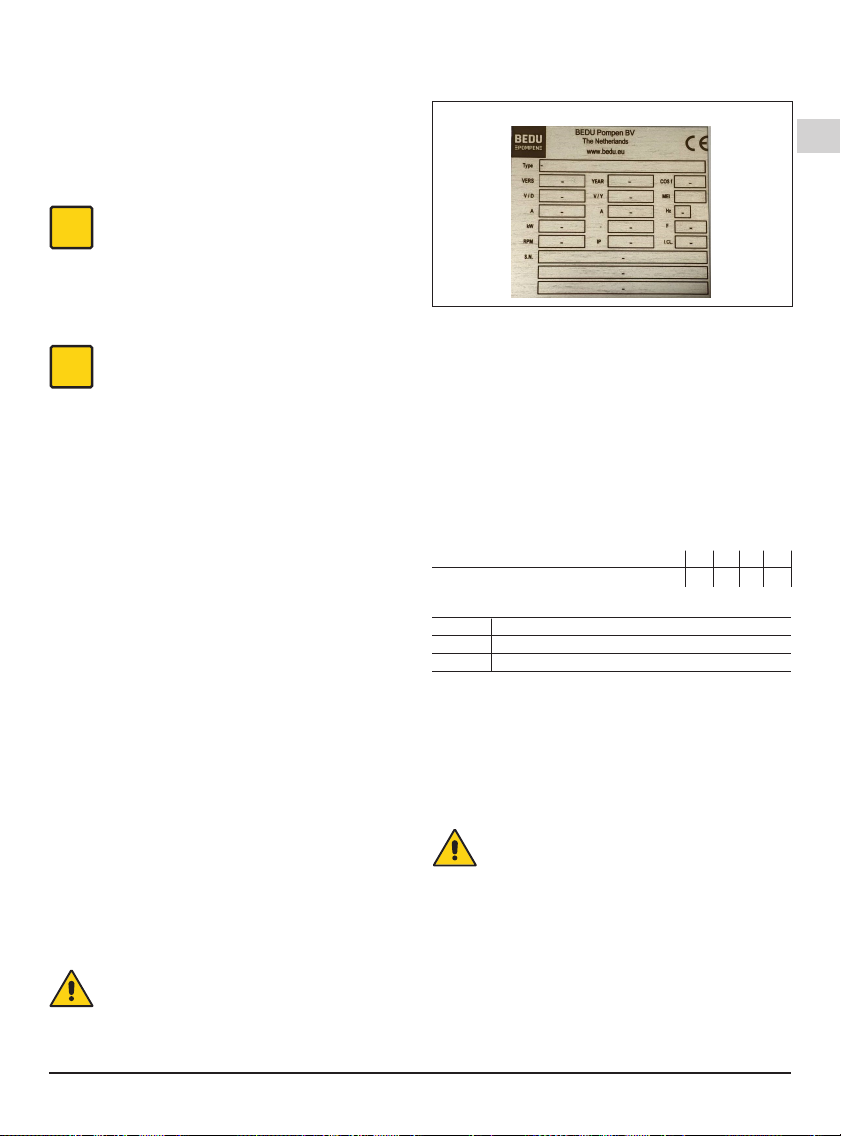
Compare the frequency and mains voltage with
the
name-plate data and connect the supply conductors
to the terminals in accordance with the appropriate
diagram inside the terminal box cover.
ATTENTION: never allow washers or other
metal parts to fall into the internal cable
opening between the terminal box and
stator. If this occurs, dismantle the motor to
recover the object which has fallen inside.
ATTENTION: with motor power rating ≥ 5.5 kW
avoid direct starting. Provide a control panel
with star-delta starting or an other starting
device.
If the terminal box is provided with an inlet gland, use
a exible power supply cord of the H07 RN-Ftype with
section of cable not less than (par. 13.1 TAB 1).
If the terminal box is provided with an inlet bushing,
connect the power supply cord through a conduit.
For use in swimming pools (not when persons are in
the pool), garden ponds and similar places, a residual
current device with IΔN not exceeding 30 mA must be
installed in the supply circuit.
Install a device for disconnection from the mains
(switch) with a contact separation of at least 3 mm in
all poles.
With a three-phase motor install an overload protection
device with curve D appropriate for the rated current
of the pump.
Single-phase CTM, TM, TPM, are supplied with a
capacitor connected to the terminals and (for 220-240
V - 50 Hz) with an incorporated thermal protector.
7. STARTUP AND OPERATION
7.1. Preliminary checks before start-up of the
pump
Do not start-up the device in case of damaged parts.
7.2. First starting
OFF
ATTENTION: never run the pump dry. Start the
pump after lling it completely with liquid.
When the pump is located above the water level
(suction lift operation) or with a positive suction head
which is too low (less than 1 m) to open the non-return
valve, ll the pump through the priming hole.
When the liquid level on the suction side is above
the pump (inow under positive suction head), ll the
pump by opening the suction gate valve slowly and
completely, keeping the delivery gate valve open to
release the air.
Before starting, check that the shaft turns by hand. For
this purpose use the screwdriver notch on the shaft
end on the ventilation side.
Slight initial rotational resistance may be due to
the reduced axial clearance of the impeller of
this type of pump; the impeller will work loose
after a short period of use.
When starting, with a three-phase motor, check
that the direction of rotation is as shown by the
arrows on the lantern bracket.
Otherwise, disconnect electrical power and reverse
the connections of two phases.
Check that the pump works within its
eld of perfor-mance and that the absorbed current
shown on the name-plate is not exceeded. Otherwise
adjust the delivery gate valve or the setting of any
pressure switches.
These pumps must never be run against a closed
valve. Never run the pump for more than ve
minutes with a closed gate valve.
7.3. Switch off of the pump
ON
The appliance must be switch off every time
there are faults. (see troubleshooting).
The product is designed for a continuous duty, the
switch off is performed by disconnecting the power
supply by means the expected disconnecting devices.
(see paragraph “6.5 Electrical connection”).
8. MAINTENANCE
Before any operations it's necessary to disconnect the
power supply.
If required ask to an electrician or to an expert
technician.
Every maintenance operations, cleaning or
reparation executed with the electrical system
under voltage, it could cause serious injuries
to people.
If the supply cord is damaged, it must be
replaced by the manufacturer, its service agent
or similarly qualied persons in order to avoid
a hazard.
In case of extraordinary maintenance, or maintenance
operations that require part-removing, the operator
must be a qualied technician able to read schemes
and drawings.
It is suggest to register all maintenance operation
executed.
i
During maintenance keep particular attention in
order to avoid the introduction of small external
parts, that could compromise the device safety.
CT,T, TP, Rev24.indd 11 15/01/18 15:46

GB
Page 12 / 64 CT,T, TP, Rev24 - Operating Instructions
It is forbidden to execute any operations with
the direct use of hands. Use water-resistant,
anti-cut gloves to disassemble and clean or in
other particular cases.
i
During maintenance operations external
personnel is not allowed.
Maintenance operations that are not described in
this manual must be made only by special personnel
authorized by Bedu Pompen BV
For further technical information regarding the use or
the maintenance of the device, contact Bedu Pompen BV
8.1. Routine maintenance
OFF
Before every maintenance operations
disconnect the power supply and make sure
that the device could not accidentally operate.
When the pump remains inactive it must be
emptied completely if there is a risk of freezing.
Remove the front cover (12.00) or the drain plug
(14.12), if available, to empty the pumps
of the T, TP series. To empty completely the CT pumps,
remove the pump and turn it upside-down.
After a long idle period, before restarting the unit,
check that the impeller is not jammed because of
incrustations, settling solids (deposit formation)
or other causes. If necessary clean with suitable
action.
8.2. Dismantling the system
Close the suction and delivery gate valves and drain
the pump casing before dismantling the pump.
8.3. Dismantling the pump
OFF
Close the suction and delivery gate valves before
dismantling.
For dismantling and re-assembly see construction in
the cross section drawing.
To remove the impeller (28.00) T, TP use the threaded
dismantling holes.
9. DISPOSAL
OFF
The nal disposal of the device must be done by
specialized company.
Make sure the specialized company follows the
classication of the material parts for the separation.
Observe the local regulations and dispose the device
accordingly with the international rules for environment
protection.
10. SPARE PARTS
10.1. Spare-parts request
When ordering spare parts, please quote their
designation, position number in the cross section
drawing and rated data from the pump name plate
(type, date and serial number).
The spare parts request shall be sent to Bedu
Pompen BV by phone, fax, e-mail.
11. ESIGNATION OF PARTS
Nr. Designation
12.00 Casing cover
12.20 Screw
14.00 Pump casing
14.04 Plug (lling)
14.12 Plug (draining)
14.20 O-ring
14.24 Screw
28.00 Impeller
28.20 Impeller key
32.00 Lantern bracket
36.00 Mechanical seal
36.50 Shoulder ring
36.52 Shoulder ring
46.00 Deector
70.00 Lantern bracket
70.18 Screw
73.00 Pump-side bearing
73.12 Circlip
76.00 Motor casing with winding
76.04 Cable gland
76.16 Support
76.35 Cover
76.54 Terminal box, set
78.00 Shaft with rotor packet
81.00 Fan-side bearing
81.08 Circlip
82.00 Motor end shield, fan side
82.04 Compensating spring
82.08 Screw
88.00 Motor fan
90.00 Fan cover
90.04 Screw
92.00 Tie-bolt
94.00 Capacitor
94.02 Capacitor gland
98.00 Terminal box cover
98.04 Screw
98.08 Gasket
99.00 Motor, complete
Changes reserved.
CT,T, TP, Rev24.indd 12 15/01/18 15:46

GB
CT,T, TP, Rev24 - Operating Instructions Page 13 / 64
12. TROUBLESHOOTING
OFF
WARNING: Turn off the power supply before performing any operations.
Do not allow the pump or motor to run when dry even for a short period.
Strictly follow the user instructions and if necessary contact an authorised service centre.
PROBLEM
PROBABLE CAUSES POSSIBLE REMEDIES
1)
The motor does
not start
1a) Unsuitable power supply
1b) Incorrect electrical connections
1c) Engine overload protective device cuts
in.
1d) Blown or defective fuses
1e) Shaft blocked
1f) If the above causes have already
been checked, the engine may be
malfunctioning
1a) Check that the mains frequency and voltage correspond to the
electrical characteristics shown on the indicator plate
1b) Connect the power supply cable to the terminal board correctly. Check
that the thermal overload protection is set correctly (see data on the
engine indicator plate) and make sure that the fuseboard upline of the
engine has been properly connected
1c) Check the power supply and make sure that the pump shaft is turning
freely. Check that the thermal overload protection has been set
correctly (see engine indicator plate)
1d)
Replace the fuses, check the electric power supply and points a) and c)
1e) Remove the cause of blockage as indicated in the “Blocked pump”
instruction booklet
1f) Repair or replace the engine by applying to an authorised service
centre
2)
Pump blocked 2a) Prolonged periods of inactivity with
formation of rust inside the pump
2b) Presence of solid bodies in the pump
rotor
2c) Bearings siezed
2a) Rotation may be started directly from the pump shaft or from the
joint (remember to turn off the electricity supply rst ) or contact an
authorised service centre
2b) If possible, dismantle the pump casing and remove any solid foreign
bodies inside the rotor, if necessary contact an authorised service
centre
2c) If the bearings are damaged replace them or if necessary contact an
authorised service centre
3)
The pump
functions
but no water
comes out
3a) Possible inltration of air from suction
tube connections, drain plugs or lling
of pump or from the gaskets of the
suction pipe
3b) Foot valve blocked or suction pipe not
fully immersed in liquid
3c) Suction lter blocked
3a) Check which part is not tight and seal the connection adequately
3b) Clean or replace the bottom valve and use a suction pipe suitable for
the application
3c) Clean the lter, if necessary, replace it . See point 2a) also.
4)
Insufcient ow 4a) Pipes and accessories with diameter
too small causing excessive loss of
head
4b) Presence of deposits or solid bodies in
the internal passages of the rotor
4c) Rotor deteriorated
4d) Worn rotor and pump case
4e) Excessive viscosity of the liquid
pumped (if other than water)
4f) Incorrect direction of rotation
4g) Suction head excessive in relation to
the suction capacity of pump
4h) Suction pipe too long
4a) Use pipes and accessories suitable for the specic application
4b) Clean the rotor and install a suction lter to prevent other foreign
bodies from entering
4c) Replace the rotor, if necessary, contact an authorised service centre
4d) Replace the rotor and the pump casing
4e) The pump is unsuitable
4f) Invert the electrical connections on the terminal board or control panel
4g) Try to close the feeder gate partially and/or reduce the difference in
level of the pump and the liquid being aspirated
4h) Bring the pump closer to the suction tank so as to use a shorter pipe.
If necessary use a pipe of a wider diameter
5)
Noise and
vibrations
from the pump
5a) Rotating part unbalanced
5b) Worn bearings
5c) Pump and pipes not rmly attached
5d) Flow too strong for the diameter of the
delivery pipe
5e) Functioning in cavitation
5f) Unbalanced power supply
5g) Incorrect alignment of pump-motor unit
5a) Check that no solid bodies are obstructing the rotor
5b) Replace the bearings
5c) Anchor the delivery and suction piping as needed
5d) Use bigger diameters or reduce the pump ow
5e) Reduce the ow by adjusting the feeder gate and/or using pipes with
a bigger internal diameter. See point 4g) too
5f) Check that the mains voltage is right
5g) If necessary, the unit must be re-aligned
6)
Leakage from
the mechanical
seal
6a) The mechanical seal has functioned
when dry or has stuck
6b) Mechanical seal scored by presence
of abrasive parts in the liquid pumped
6c) Mechanical seal unsuitable for the
type of application
6d) Slight initial drip during lling or on rst
start-up
In cases 6a), 6b) and 6c), replace the seal, if necessary contact an
authorised service centre
6a) Make sure that the pump casing (and the suction pipe if the pump is
not self-priming) are full of liquid and that all the air has been expelled.
See point 5 e) too.
6b) Install a suction lter and use a seal suited to the characteristics of the
liquid being pumped.
6c) Choose a seal with characteristics suitable for the specic application
6d)
Wait for the seal to adjust to the rotation of the shaft. If the problem
persists, see points 6a), 6b) or 6c) or contact an authorised service centre.
CT,T, TP, Rev24.indd 13 15/01/18 15:46

62 / 64 CT,T, TP, Rev24
13. Drawing for dismantling and assembly
90.04
76.00
78.0073.00
36.00 92.0046.00
70.1836.50
14.12
12.20
81.00
82.04
94.0276.04
94.0076.54
98.0098.08
14.00 98.0470.00
14.04
82.00
90.00
88.00
3.94.112
28.20
28.00
12.00
14.20
3.94.114
14.00 14.24
12.24 32.0014.12
3.94.113
14.00 32.00
14.24 76.1614.12
14.00
12.00
3.94.059
T 76, TP 80, T 100, TP 100
T 125 TP 132 T 61,65,70
TP 78
CT,T, TP, Rev24.indd 62 15/01/18 15:46

CT,T, TP, Rev24 63 / 64
98.04
46.00
28.00
76.00
14.00
14.04
76.04
94.00
76.54
98.00
76.35
82.00
88.00
82.04
82.08
81.00
81.08
78.00
73.12
73.00
36.00
14.20
36.52
36.50
90.0014.24
3.94.052
13. Drawing for dismantling and assembly
组装与分解图
CT 61
Tab. 1 TAB 1IEC 60335-1
Amm 2
Corrente nominale dell'apparecchio
Rated current of appliance
Bemessungsstrom des Gerätes
设备额定运行电流
Sezione nominale
Nominal cross-sectional area
Nennquerschnitt
导体额定截面积
>3
>6
>10
>16
>25
>32
>40
0,75
1,0
1,5
2,5
4
6
10
≤6
≤10
≤16
≤25
≤32
≤40
≤63
÷
÷
÷
÷
÷
÷
÷
13.1. Minimum cross-sectional area of conductors
CT,T, TP, Rev24.indd 63 15/01/18 15:46

EC – Declaration of Conformity
Manufacturer Details
Tradename
Bedu Pompen BV
Ad
d
res
s
Poort van Midden Gelderland Rood 10, 6666 LT, Heteren, Ne
therlands
Product Details
Product Na
me
Centrifugal pumps
Model (+series) Name
CT, T, TP series
Applicable Standards Details
Directives
2006/42/EC (Machinery Directive)
2014/35/EU (Low Voltage Directive)
2014/30/EU (Electromagnetic compatibility)
Standards
EN-ISO 12100:2010
EN-IEC 60204-1:2006
EN 809+A1/C1
Additional
informati
on
No further details.
Declaration
We hereby declare under our sole responsibility
that the product(s) mentioned above to which this
declaration relates complies with the above
mentioned standards and Directives.
BEDU Pompen BV
Poort van Midden Gelderland Rood 10
6666 LT Heteren
Tel : +31 (0)88 – 4802 900
Fax : +31 (0)88 – 4802 901
Website : www.bedu.eu
Business Unit Manager:
Issued Date
:
01/10/ 2014
Marco Breunissen
Signature of representative(s)


Expert advice
A customer-oriented organization
that adapts to the requirements and
wishes of your organization
Innovative and customized solutions
Breakdownservice, 24 hours a day, 7
days a week
Technical service with extensive test
facilities, working from our own
workplace or at your location
A fast and appropriate solution for
all your issues
Wide range of liquid pumps
Repair, maintenance and revision
made for your process
BEDU POMPEN B.V.
Poort van Midden Gelderland Rood 10
6666 LT HETEREN
Nederland
Telefoon +31 (0)88 4802 900
E-mail info@bedu.eu
WWW.BEDU.EU
BEDU BELGIUM B.V.B.A.
Industriepark-West 75
9100 SINT-NIKLAAS
België
Telefoon +32 (0)3 80 87 980
E-mail [email protected]
WWW.BEDU.BE
This manual suits for next models
13
Table of contents