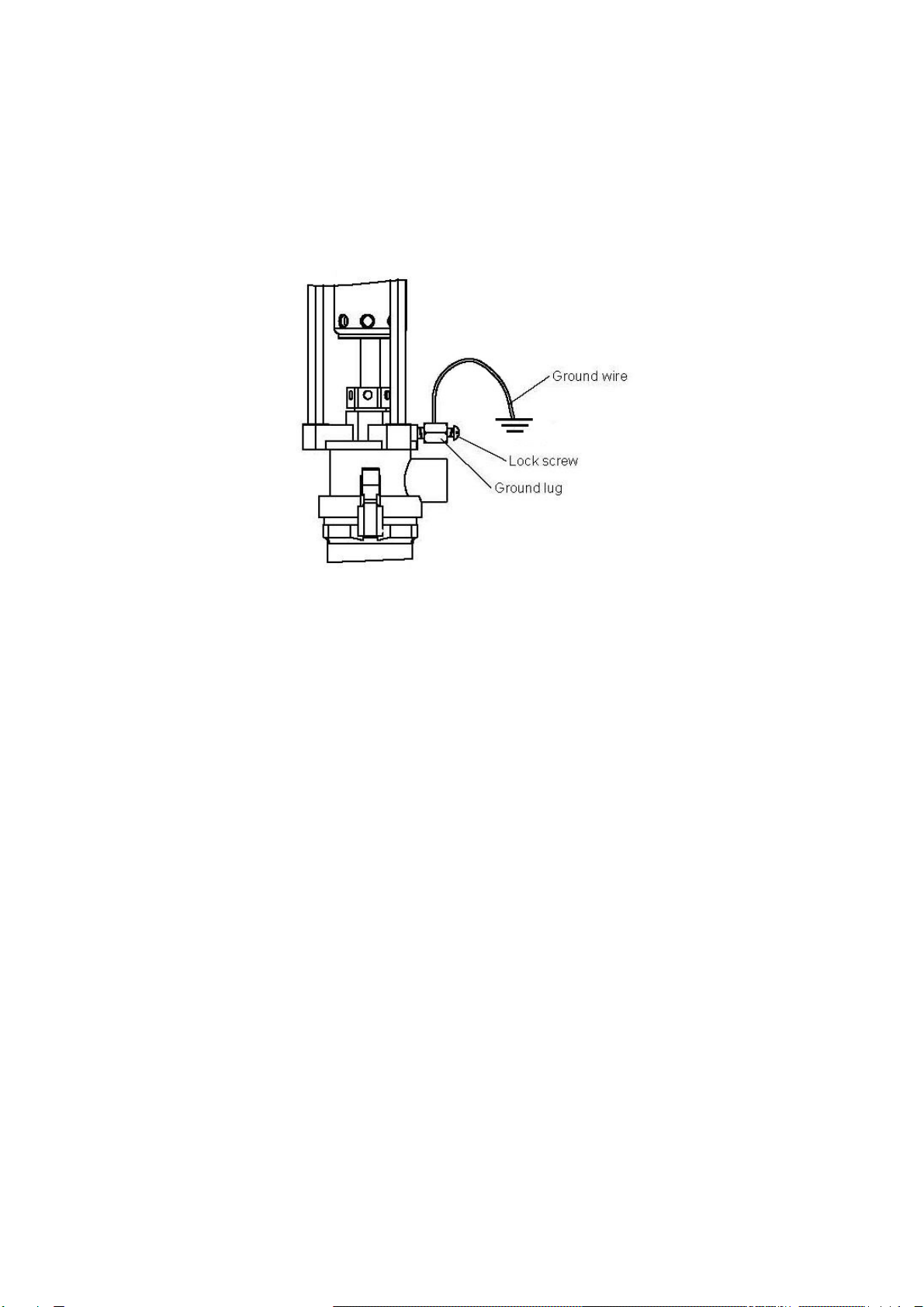
IPM OP 820301 User manual

820301,820302,820303
OP SERIES
2:1 RATIO TRANSFER PUMP
OPERATIONING MANUAL
WITH
PARTS IDENTIFICATION
IPM, INC.
Manufactured by International Pump Manufacturing, Inc®.

2
OP series
2:1 RATIO TRANSFER PUMP
OPERATIONS MANUAL and
PARTS IDENTIFICATION DRAWINGS
This manual contains IMPORTANT WARNINGS and INSTRUCTIONS. Read and retain for future reference.
INTERNATIONAL PUMP MANUFACTURING, INC.
3107 142nd Avenue E Suite 106,
Sumner, WA 98390
U.S.A.
TEL: (253) 863 2222
FAX: (253) 863 2223
Website : www.ipmpumps.com
For Technical Service Call Your Local Distributor
Copyright 2016 by: International Pump Mfg, Inc.
WARNING: The equipment described herein must only be operated or
serviced by properly trained individuals thoroughly familiar with the
operating instructions, mechanics and limitations of the equipment.
Notice: All statements, information and data given herein are believed to be accurate and reliable but are presented without guarantee, warranty
or responsibility of any kind expressed or implied. Statements or suggestions concerning possible use of IPM equipment are made without
representation or warranty that any such use is free of patent infringement, and are not recommendations to infringe any patent. The user should
not assume that all safety measures are indicated or that other measures may not be required. IPM reserves the right to make changes at any
time without notice.

3
TABLE OF CONTENTS
1.0 SAFETY WARNINGS 4
1.1 Pump and component grounding procedures 7
2.0 INSTALLATION 9
2.1 Pump installation/set-up 9
2.2 Disassembly – air motor section 11
3.0 PARTS IDENTIFICATION 14
3.1 Air motor section assembly (700004) 14
3.2 Parts list for 820301,820302,820303 (Air motor section) 15
3.3 Parts list for 820301 (Fluid section) 16
3.4 Parts list for 820302 (Fluid section) 17
3.5 Parts list for 820303 (Fluid section) 18
4.0 REPAIR KITS 19
5.0 TROUBLESHOOTING 20
6.0 TECHNICAL SPECIFICATIONS 21
7.0 PERFORMANCE 22
8.0 WARRANTY AND DISCLAIMER 24

4
1.0 SAFETY WARNINGS
Please read and observe all warnings contained in this operations manual before making any
attempt to operate the equipment.
Misuse of equipment
Misuse of equipment can cause serious bodily injury. Use the equipment only for its intended
purpose and do not attempt to modify it in any way. Care should be taken to prevent over
pressurization of the pump, hose lines and accessories connected to it. Use only IPM designated
parts for re-building or repairing this equipment. Use the pump only with compatible fluids.
Improper use of this equipment could result in fluid being sprayed on the skin or in the eyes of
user, serious bodily injury, property damage, fire or explosion.
Daily maintenance inspection should be made on pumps and equipment and all worn or
damaged parts should be re-placed immediately. Do not use pumps, components or hose lines
as leverage to move equipment to avoid damage and injury. Do not alter this equipment as doing
so could cause it to function incorrectly and/or cause serious injury. Altering this equipment in
any way will also void any and all warranty guarantees from the manufacturer.
Material & fluid compatibility
Always ensure the chemical compatibility of the fluids and solvents used in the fluid section of
these pumps, hoses other components. Check the chemical manufacturer’s data sheets and
specification charts before using fluids or solvents in this pump to ensure compatibility with
pumps, inner hose lining and outer hose covering.
Pressurized hoses
Because the hoses are pressurized they can present a danger should the fluid escape due to
damage, worn parts or general miss-use. Escaping fluid can splash or spray operator, causing
serious bodily injury and/or damage to equipment and property. Ensure that the hoses do not
leak or rupture due to wear, misuse or damage.
Before each use, ensure that the fluid couplings are tight and all clips/pins/plugs are secured.
Inspect the entire length of hose for wear, cuts, abrasions, bulging cover and/or loose
connections. These conditions may cause the hose to fail and result in splashing or spraying of
chemicals on the skin or in the eyes of operator and cause serious injury and/or property
damage.
Warning
To reduce the risk of static sparking or splashing fluid in the eyes or on the skin, follow
the Pressure Relief Procedure before flushing.
For your safety, read the Fire or Explosion Hazard before flushing and follow all the
listed recommendations.

5
Pressure specification
The maximum working pressure of this equipment for fluids and air is 180 psi (12.5 bars). Ensure
all equipment and accessories used with this pump are rated to withstand the maximum working
pressure of this pump. Never exceed the maximum working pressure of the pump, hose lines or
any other components attached to the pump itself.
Procedure for pressure relief
In order to avoid the risk of serious injury to operators from splashing/spraying chemicals, the
following safety procedures should be used. This procedure should be used when shutting down
the pump, performing general maintenance, repairing a pump or other components of the system,
replacing components or when pumping operation is ceased.
1 Close the air valve to the pump.
2 Use the air bleed down valve (see INSTALLATION) to relieve the air pressure in the system.
3 Relieve the fluid pressure by holding a grounded metal pail in contact with the metal part of
the fluid dispense valve and slowly opening the valve.
4 With a container ready to catch the fluid, open the drain valve (see INSTALLATION).
5 It is a good practice to leave the drain valve open until it is time to dispense fluid again.
If you are unsure that the fluid pressure has been relieved due to a blockage in a component or a
hose, carefully relieve the pressure by carefully loosening the hose end coupling to allow the fluid
pressure to escape slowly. After the pressure has been relieved, the fitting can then be removed
and any blockages removed. If the pump is to remain idle for only a short period of time, it is not
necessary to empty the wet cup.
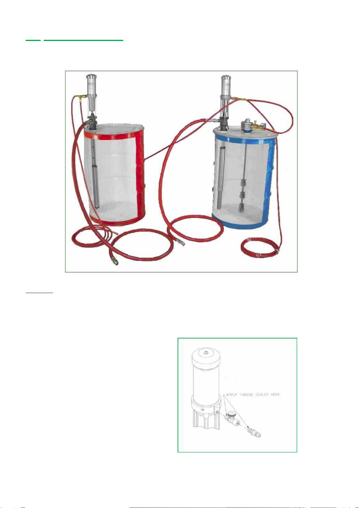
Flush the pump before initiating operation
1 The pump is tested with lightweight DOP oil, which is left in to protect the pump parts. If the
fluid you are pumping may become contaminated by oil, flush oil from pump with a
compatible solvent before use. Follow the flushing instruction below.
2 When pumping fluids that set up or solidify, flush the system with a compatible solvent as
often as necessary to remove build-up of solidified chemicals in the pump or hoses.
3 If the pump is being used to supply a circulating system, allow the solvent to circulate through
the entire system for at least 30 minutes every 48 hours or more often if necessary to prevent
settling and solidification of chemicals.
4 Always fill the wet-cup 1/2 full of throat seal liquid (TSL) or compatible solvent to keep the
fluid from drying on the displacement rod and damaging pump throat packing.
5 Lubricate the throat packing frequently, when you are pumping a non-lubricating fluid or are
shutting down for more than one day.

6
6 IPM transfer pumps incorporates a wet tube, the purpose of which is to prevent the buidup of
chemical and dirt on the pump shaft which would damage the packing as the shaft
reciprocates through them. This wet tube must be full when a pump that has not been
thoroughly flushed and cleaned is stored outside the protected environment of a sealed drum
as well as when the pump is in use. Should a pump be installed in a partially filled drum
where the liquid level is below the top of the wet tube, the tube must be manually filled with
the proper chemical prior to inserting into the drum.
7 Once a pump is committed to a particular chemical, it is good practice to identify which
chemical a particular pump is designated for to eliminate the possibility of mix up and
contamination.
Shut down & care of pump
For overnight shut down, follow the Pressure Relief Procedure (page 5). Always stop the pump
at bottom of the stroke to prevent the fluid from drying on the exposed displacement rod and
damaging the throat packing.
Hazards from fire or explosion
Hazards exist where sparks can ignite vapors or fumes from combustible chemicals or other
hazardous conditions exist such as explosive dust, etc. These sparks can be created from
plugging in or unplugging an electrical supply cord or from the static electricity generated by the
flow of fluid through the pump and hose.
Every part of the equipment must be properly grounded to prevent static electricity from
generating a spark and causing the pump or system to become hazardous. These sparks can
cause a fire, explosion, property and equipment damage and serious bodily injury. Ensure that
the pump and all components and accessories are properly grounded and that electrical supply
cords are not plugged in or unplugged when these hazards exist.
Should any evidence of sparks or static electricity exist, discontinue pump operation immediately.
Investigate the source of the static electricity and correct the grounding problem. Do not use the
system until the grounding problem is repaired.

7
1.1 Pump and component grounding procedures
Always use the following procedures for grounding the pump. Loosen the lock screw to allow
insertion of one end of a minimum size 12 gauge wire into the bore hole of the grounding lug.
Insert wire and tighen the lock screw securely. Secure the other end of the ground to a true earth
ground. Grounding of the pump and all components is necessary to minimize the possibility of
sparks due to static electricity. Grounding must be in compliance with local electrical codes.
Check with the local authorities for requirements in your area and with the type of equipment
being used.
Figure A
Ensure that all the following equipment is grounded correctly:
1. Air compressor: Follow the grounding procedures as recommended by the
compressor manufacturer
2. Air hoses: Always use grounded air houses.
3. Fluid container used
to supply the system: Grounding must be done according to local electrical codes.
4. Pump: Follow the procedures referred to in Figure A (page 6).
5. Fluid Hoses: Always use grounded fluid hoses.
6. Dispensing Valve: The valve must be metal to conduct through the fluid hose to the
pump which must be properly grounded.
7. Dispensing Point: Grounding must be done according to local electrical codes.
8. Solvent Containers
use only metal: Grounding must be done according to local electrical codes.
Conductive pails that are properly grounded.
9. Grounding while
dispensing, cleaning
or relieving pressure:
Maintain conductivity by firmly securing the metal part of the
dispensing valve to the side of a grounded metal container.

8
Hose grounding
It is very important that the hoses used for both air and fluid dispensing be a grounding type and
that ground continuity is maintained at all times during operation. Regular checks of the hose
ground resistance (with a resistance meter using a suitable range) and a comparison to the
manufacture’s specification will ensure that the ground is within specifications. If it is not within
specified limits it should be replaced immediately.
Solvent cleaning
While cleaning the system with solvent, secure the metal part of the dispensing valve in contact
with a grounded metal pail to minimize the possibility of splashing/spraying of chemicals on the
skin, in the eyes and around static sparks. Use low fluid pressure for additional safety.
Hazards from moving parts
Use the pressure Relief Procedure to prevent the pump from starting un-intentionally or
unexpectedly. Be aware of moving parts that present a pinching hazard to fingers or other body
parts. Stay clear of these moving parts at all times when starting or operating the pump.
Safety standards
Safety standards have been established by the United States Government under the
Occupational Safety and Health Act. These standards should be consulted as they apply to the
hazards and type of equipment being used.

9
2.0 INSTALLATION
Typical plural system configuration with drum mixer
Figure A - Set-up picture showing ISO and resin equipment installation with OP232C pump,
OP242CD pump and drum mixer.
2.1 Pump installation / set-up
1. Use thread sealer on the male threads
of the ball valve and quick disconnect
plug. Install in the air inlet as shown.

10
2. Screw the bung adapter onto the
drum opening tightly. Carefully slide
the transfer pump through the adapte
r
and lock it in place with the bung
adapter latch hooks.
3.
A
ttach air line onto quick disconnect fitting to
complete installation. It is recommended to use a
minimum 3/8” hose for the pump air supply.

11
2.2 Disassembly – air motor section
1. Disconnect all air and hydraulic pressure from pump for safety.
2. Place the pump in a vice being careful not to damage equipment. Pipe clamps will serve in
the event you do not have a vice available.
3. Remove the air bleed plug.

12
4. Place a strap wrench around the
lower end of the air cylinder and
carefully unthread.
5. Use a 5/16” steel dowel pins to keep
the piston rod plunger from rotating.
Unthread.
6. Remove the dowel pin from the plunger
top. Air motor assembly can now be
removed from the displacement
plunger.

13
7. Push the piston out through the
suction tube.
8. Inspect and replace the packings as
required paying careful attention to
the packing orientation.
9. Lubricate, install, and assembly the parts in reverse order. Lubrication is recommended for
use on the air cylinder walls and all of the components within the air motor assembly.

14
3.0 PARTS IDENTIFICATION
3.1 Air motor section assembly (700004)
Note: Upper hex nut is a permanent of upper air valve plate (#700003). Do not use a wrench on
hex nut during disassembly, assembly or maintenance of air motor assembly.
NOTE: When replacing
Lower Air Valve (500013)
and the Socket Head Cap
Screws (500014), it is
important that a Liquid
Thread Sealing
Compound be used to
prevent the assembly
from vibrating loose.

15
3.2 Parts list for 820301,820302,820303 (Air motor section)

16
3.3 Parts list for 820301 (Fluid section)

17
3.4 Parts list for 820302 (Fluid section)

18
3.5 Parts list for 820303 (Fluid section)

19
4.0 REPAIR KITS
601018 Air motor section repair kit
Fits: 820301, 820302, 820303
Components include
Part # Description Qty
500006 O-ring 2
500015 Gasket 1
500016 Gasket 3
500017 Wear ring 1
500018 U-cup 1
500019 O-ring 1
500023 O-ring 1
500030 U-cup 1
601035 Fluid section repair kit
Fits: 820301, 820302, 820303
Components include
Part # Description Qty
500033 Seal retainer 1
500034 Packing 2
500035 Seal expander 1
500036 Shaft wiper ring 1
500041 Gasket 1
500042 O-ring 1
500053 Gasket 2
500054 Lower roll pin 1
500055 Upper roll pin 1
500056 Viton O-ring 1
500061 Piston packing cup 1
500063 U-cup 1
500064 Wear ring 1
500066 O-ring 2
500237 O-ring; OP242CD ONLY 1

20
5.0 TROUBLESHOOTING
Problem Causes Recommended
Solutions
Air supply or pressure is
inadequate. Air lines restricted. Increase air pressure.
Check for any restrictions in air line.
Dispensing valve is not open or
clogged. Open and/or clear foot valve.
Pump does not operate. Clogged fluid lines, valves,
hoses or damaged air motor.
Follow pressure relief procedure to
clear obstruction.
Service air motor. Replace parts as
necessary.
Depleted or exhausted fluid
supply. Refill fluid. Prime system or flush it.
Worn or damaged air motor
gasket, packing, seal, etc Service air motor. Replace parts as
necessary.
Non-stop air exhaust. Intake valve or packing worn off. Replace worn parts
Erratic pump operation. Intake valve is not completely
closed. Clear obstruction and service pump.
Replace parts as necessary.
Held open or worn intake valve. Clear obstruction and service pump.
Replace parts as necessary.
Low output on upstroke.
Held open or worn piston valve. Clear obstruction and service pump.
Replace parts as necessary.
Low output on down
stroke. Restriction in air lines or air
pressure low. Increase air pressure or supply.
Closed or clogged valves. Open valve or clear valve.
Fluid supply is insufficient or
exhausted. Refill fluid. Prime system or flush it.
Low output on both
strokes.
Obstructions in fluid lines,
hoses, valves, etc. Follow pressure relief procedure,
then clear obstruction.
This manual suits for next models
3
Table of contents
Other IPM Water Pump manuals
Popular Water Pump manuals by other brands

FLOJET
FLOJET G70C Series Installation & Operation Information

Pentair
Pentair JUNG PUMPEN U 3 K/2 instruction manual

Kessel
Kessel Aqualift S Installation and operating instructions

Davey
Davey XF111SS Installation and operating instructions

PondMAX
PondMAX Ultra CW750 instruction manual

iPA
iPA 9060 Operator's manual

Edwards
Edwards T-Station 300 instruction manual

BUSCH
BUSCH COBRA NC 1000 B instruction manual

Hi-Force
Hi-Force ATDP63 Operating instructions manual

BUSCH
BUSCH COBRA ATEX NC 2000 B VR instruction manual

China Nanfang Pump
China Nanfang Pump SZ Series Operation manual

Gast
Gast ROA Series Operation & maintenance manual