bee 71MS Product guide

G.Bee
GmbH
Kugelhähne
&
Sicherheitsarmaturen
Ball
Valves
&
Safety
Valves
G.Bee
GmbH
■
Pottfach
1161
■
71687
Freibarg
a.N.
■
Germany
Bedienungs-
und
Montageanleitung
für
Flansch
-
Kugelhähne
Typ
71
ME
und
71
MS
mit
Antimonimprägniertem
Kohledichtsystem
PN
16
/
PN
40
1.
Anwendungsbereich
Kugelhahn
mit
vollem
Durchgang,
der
als
Absperrarmatur
im
Anlagenbau
vor
allem
bei
hohen
Temperaturen
Verwendung
findet.
(
z.B.
Wärmeträgeröle
)
PED
2014/68/EU
Kategorie
3
Modul
H
Hinweis:
Die
Armatur
muss
nach
den
Anforderungen
der
EN
19
gekennzeichnet
sein.
Temperaturbereich:
Typ
71MS
-20°C
bis
+
400°C
Typ
71
ME
-50°C
bis
+
300°C
2.
Einbau
/
Montage
Bee
Flansch
-
Kugelhähne
werden
grundsätzlich
in
Offenstellung
geliefert.
Der
Einbau
soll
in
der
Regel
auch
in
Offenstellung
erfolgen.
Vor
der
Montage
müssen
die
Schutzkappen
entfernt
werden.
Die
Montage
muss
fachgerecht
mittels
geeigneter
Schrauben
und
Dichtungswerkstoffe
erfolgen.
Reaktionskräfte-
und
Momente
(
Spannungen
des
Leitungssystems
)
dürfen
die
in
DIN
EN
13774
geforderten
max.
Biegemomente
nicht
überschreiten.
Nach
dem
Einbau
ist
ein
Ausspülen
des
Leitungssystems
erforderlich,
um
Installationsrückstände
zu
entfernen
und
eine
eventuelle
Beschädigung
der
Kugeldichtung
zu
verhindern.
3.
Bedienung
Schließen:
90°
Drehung
des
Bedienungshebels
im
Uhrzeigersinn.
Öffnen:
90°
Drehung
des
Bedienungshebels
gegen
den
Uhrzeigersinn.
Die
Eingefräste
Kerbe
der
Schaltspindel
zeigt
die
Kugelstellung
-
Offen
/
Geschlossen
an.
Der
Kugelhahn
darf
nur
in
Offen-
oder
Geschlossenstellung
betrieben
werden.
Zwischenstellungen
(
Regelfunktion
)
beschädigen
die
Kugeldichtung.
Dies
kann
zur
Undichtheit
der
Absperrfunktion
führen.
4.
Wartung
Bee
Flansch
-
Kugelhähne
sind
wartungsfrei.
5.
Verschleiß
Der
Verschleiß
hängt
maßgebend
vom
Medium,
Schalthäufigkeit,
Temperaturbeanspruchung,...ab
Daher
können
je
nach
Anwendung
unterschiedliche
Verschleißfaktoren
auftreten,
die
sehr
unterschiedliche
Reparaturintervalle
notwendig
machen.
6.
Sonstiges
Bei
unsachgemäßer
Montage
oder/und
Bedienung
erlischt
jeglicher
Gewährleistungsanspruch.
Im
Reparaturfall
darf
der
Kugelhahn
nur
im
Herstellerwerk
geöffnet
werden.
Herstellererklärung:
Dieses Produkt
wurde
gemäß
den
technischen
Richtlinien
und
DIN-EN
Normen
hergestellt.
Die
zur
Herstellung
unserer
Produkte
verwendeten
Werkstoffe
entsprechen
den
Vorschriften
nach
AD
2000.
Wir
erklären
die
Konformität
mit
der
Druckgeräterichtlinie
2014/68/EU
Kategorie
3
Modul
H
Hausanschrift:
Robert-Bosch-Straße
14
71691
Freiberg
a.N.
Germany
Telefon:
+49
(0)
7141-9744-0
Telefax:
449
(0)
7141
-9744-155
E-Mail:
Internet:
www.g-bee.de
USt-WNr.:DE144858516
Bankort:
Kreissparkasse
Ludwigsbura
(BLZ
60450050)
7008816
IBAN
DE52
6045
0050 0007
0088
16
■
SWIFT/BIC:
SOLA
DE
S1
LBG
Volksbank
Ludwigsburg
(BLZ
60490150)
430076002
IBAN
DE30
6049
0150
0430
0760 02 SWIFT:
GENO
DE
S1
LBG
BW-Bank
(BLZ
60050101)
8183235
IBAN
DE88
6005
0101
0008
1832
35
■
SWIFT:
SOLA
DE ST
Postbank
Stuttgart
(BLZ
60010070)
4990-701
IBAN
DE21
6001
0070 0004
9907
01
SWIFT/BIC:
PBNK
DE
FF
Rechtsgültige
Firmierung:
G.Bee
GmbH
Sitz:
Frelberg
am
Neckar,
Robert-Bosch-Straße
14
Amtsgericht
Stuttgart
HRB
300
631
Geschäftsführer:
Dipl.-Ing.
Norbert
Layer

G.Bee
GmbH
Kugelhähne
&
Sicherheitsarmaturen
Ball
Valves
&
Safety
Valves
G.Bee
GmbH
■
Pottfach
1161
-
71687
Freiberg
a.N.
•
Germany
Konformitätserklärung
gemäß
Anhang
4
der
Druckgeräterichtlinie
2014/68/EU
Hersteller:
G.
Bee
GmbH
Robert-Bosch-Straße
14
D-71691
Freiberg
a.
N.
Beschreibung:
Kugelhahn
mit
vollem
Durchgang,
der
als
Absperrarmatur,
im
Rohrleitungsbau,
als
drucktragendes
Ausrüstungsteil
im
Sinne
der
EG-Druckgeräterichtlinie
sowie
im
Anlagenbau
Verwendung
findet.
Dichtsystem
Variante
D:
Antimonimprägnierte
Kohle
98%
Reingraphit
Typbezeichnung:
71
ME
=
Edelstahlausführung
71
MS
=
Stahlausführung
Angewandte
Konformitätsbewertungsverfahren:
Modul
H
(
umfassende
Qualitätssicherung
)
benannte
Stelle
TÜV
Rheinland
(CE-0035)
Angewandte
Regelwerke:
Einteilung
Werkstoffe
Auslegung
Flanschanschluss
Baulänge
Montageflansch
Prüfungen
Kennzeichnung
Regelwerke
AD2000
-
W2,
-W5,
DIN
EN
12516
AD2000-A4,
EN-1092-1
EN
-
558-1
ISO-5211
DIN
EN
12266-1
Leckrate
B
EN
19
PED
2014/68/EU
Wir
erklären,
dass
das
Produkt
mit
der
Richtlinie
2014/68/EU
übereinstimmt
und
oben
genannten
Konformitätsbewertungsverfahren
unterzogen
wurde.
Risikoanalyse:
Die
Kugelhähne
der
Baureihe
71
MS
/
71
ME
sind
auf
Belastungen
ausgelegt,
die
der
beabsichtigten
Verwendung
und anderen nach
vernünftigem
Ermessen
vorhersehbaren
Betriebsbedingungen
angemessen
sind.
Insbesondere
sind
folgende Faktoren
zu
berücksichtigen.
Druckbelastung:
Die
Druckbelastung
muss
in
dem
angegebenen
Druckbereich
liegen.
Gegen
eine
Drucküberschreitung
sowie
Druckschläge
sind
geeignete
Maßnahmen
zu
ergreifen.
Zu
Prüfzwecken
z.B.
Dichtheit
der
Flanschverbindung,
kann
die
Armatur
nach
den
Vorschriften
der
DIN
EN
12266-1
P10,
P11
geprüft
werden.
Die
innere
Dichtheit
kann
mit
1,1xBetriebsdruck
in
Durchflußrichtung
geprüft
werden
(P12).
Kugelhähne,
die
zuvor
einer
Druckprüfung
des
Sitzes
mit
Flüssigkeit
(P12)
und
Drücken
größer
1,1xBetriebsdruck
unterzogen
wurden,
können
bei
niederen
Differenzdrücken
eine
verminderte
Gebrauchstauglichkeit
aufweisen.
Temperaturbelastung:
Die
Temperaturgrenzen
müssen
entsprechend
der
Dichtungsvariante
bzw.
Werkstoffvariante
eingehalten
werden.
Das
Druck
Temperaturdiagramm
ist
zu
berücksichtigen.
Beständigkeit
gegenüber
dem
Medium:
Alle
Werkstoffe
sind
auf
dem
Datenblatt
aufgeführt.
Die
chemische
Verträglichkeit
muss
sichergestellt
sein.
Reaktionskräfte:
Reaktionskräfte
und
-Momente
im
Zusammenhang
mit
Trageelementen,
Rohrleitungen
Befestigungen
usw.
dürfen
folgende
Werte
nicht
überschreiten.
Max.
zulässige
Biegemomente:
DN15
150Nm,
DN20
200Nm,
DN25
500
Nm,
DN32
600Nm,
DN40
800Nm,
DN50
1000
Nm,
DN65
+
DN80
1500
Nm
DN100
2200
Nm
Durch
Auslegung
und
Bau
muss
folgendes
sichergestellt
sein:
Der
Gefahr
einer
Überbeanspruchung
durch
unzulässige
Bewegung
oder
übermäßige
Kräfte
z.B.
an
Armaturen
ist
durch
Unterstützung,
Befestigung,
Ausrichtung
in
geeigneter
Weise
vorzubeugen.
Bei
gasförmigen
Fluiden,
die
Kondensflüssigkeiten
bilden
sind
geeignete
Einrichtungen
zur
Entwässerung
zur
Vermeidung
von
Schäden
durch
Wasserschlag
und
Korrosion
vorzusehen.
Die
Gefahr
von
Ermüdungserscheinungen
durch
Vibration
des
Rohrleitungssystems
ist
gebührend
zu
berücksichtigen.
Freiberg
a.N.
26.01.2017
Michael
Boger
Konstruktion
/
Entwicklung
Untersch
Hausanschrift:
Robert-Bosch-Straße
14
71691
Freiberg
a.N.
Gormany
Telefon:
449
(0)
7141-9744-0
Telefax:
+49
(0)
7141-9744-155
E-Mail:
lnfoeg-bee.de
Internet:
www.g-bee.de
USt-WNr.:
DE144958516
Banken:
Kreissparkasse
Ludwigsburo
(BLZ
60450050)
7008816
IBAN
ÖE52
6045
0050 0007 0088
16
SWIFT/BIC:
SOLADES1
LBG
Volksbank
Ludwigsburg
(BLZ
60490150)
430076002
IBAN
DE30
6049
0150 0430
0760
02
SWIFT:
GENO
DE
S1
LBG
BW-Bank
(BLZ
600
50101)
8183235
IBAN
DE88
6005
0101
0006
1832
35
■
SWIFT:
SOLA
DE ST
Postbank
Stuttgart
(BLZ
60010070)
4990-701
IBAN
DE21
6001
0070
0004 9907
01
SWIFT/BIC:
PBNK
DE
FF
Rechtsgültige
Firmierung:
G.Bee
GmbH
Sttz:
Freiberg
am
Neckar.
Robert-Bosch-Straße
14
Amtsgericht
Stuttgart
HRB
300
631
Geschäftsführer:
Dipl.-Ing.
Norbert
Layer

G.Bee
GmbH
Kugelhähne
&
Sicherheitsarmaturen
Ball
Valves
&
Safety
Valves
tu
G.Bee
GmbH
■
Portfach 1161
•
71687
Freiberg
a.N.
■
Germany
Operating
and
assembly
instructions
for
BEE
flange
ball
valves
series
71
MS
and
71
ME
with
antimon
impregnated
coal
seal
System
PN
16
/
PN
40
1.
Field
of
application
Ball
valve
with
füll
passage
used
as
a
shut-off
valve
for
pressure-bearing
plant
components
mainly
for
high
temperature
applications.
(
p.e.
thermal
oil)
PED
2014/68/EC
cat.
3
module
H.
Note:
The
valve
must
be
marked
in
line
with
the
requirements
of
EN19
Temperature
ränge:
series
71
MS
-20°C
to
+
400°C
series
71
ME
-50°C
to
+
300°C
2.
Installation
/
Assembly
BEE
flange
ball
valves are
basically
supplied
in
the
open
position.
As
a
general
rule
they
should
also
be
installed
in
the
open
position.
The
protective
caps
must
be
removed
prior
to
assembly.
They
should
be
assembled
correctly
using
appropriate
bolts
and
sealing
materials.
Reaction
forces
and
moments
(stresses
of
the
pipe
System)
should
notexceed
the
maximum
moments
of
flexion
laid
down
in
DIN
EN
13774.
Following
installation,
the
pipe
System
must
be
flushed
out
in
order
to
remove
any
residual
matter
and
to
prevent
possible
damage
to
the
ball
seal.
3.
Operation
To
dose:
Turn
the
operating
lever
90°
clockwise.
To
open:
Turn
the
operating
lever
90°
anti-clockwise.
The
notch
in
the
switch
spindle
indicates
the
ball
position
-
Open
/
Closed.
The
ball
valve
may
only
be
operated
in
Open
or
Closed
position.
Intermediate
positions
(control
function)
can
damage
the
ball
seal.
This
can
cause
leakage
in
the
shut-off
function.
4.
Maintenance
BEE
flange
ball
valves
need
no
maintenance.
5.
Wear
The
wear
depends
to
a
considerable
extent
on
the
medium,
frequency
of
switching
actuations,
and
temperature
stress,...
For
this
reason
various
wearing
factors
can
occur
according
to
the
particular
application,
necessitating
very
different
repair
intervals.
6.
Miscellaneous
Incorrect
assembly
and/or
Operation
will
invalidate
the
right
to
make
Claims
under
the
warranty.
In
the
event
of
repair
the
ball
valve
may
only
be
opened
in
the
manufacturer's
plant.
Declaration
of
the
manufacturer
This
product
has
been
manufactured
in
accordance
with
the
technical
guidelines
and DIN
Standards.
The
materials
used
to
manufacture
our
products
comply
with
the
regulations
according
to
AD
2000.
We
hereby
declare
the
conformity
with
the
PED
97/23/EEC
categorie
3
module
H
Hausanschrift:
Robert-Bosch-Straße
14
71691
Freiberg
aN.
Germany
Telefon:
449
(0)
7141-9744-0
Telefax:
+49
(O)
7141-9744-155
E-Mail:
Info0g-bee.de
Internet:
www.g-beo.de
USt-ldNr:
DE144958516
Banken:
Kreissparkasse
Ludwigsburg
(BLZ 60450050) 7008
816
IBAN
DE52
6045
0050
0007
0088
16
■
SWIFT/BIC:
SOLA
DE
S1
LBG
Volksbank
Ludwigsburg
(BLZ
60490150)
430076002
IBAN
DE30
6049
0150
0430
0760 02 SWIFT:
GENO
DE
S1
LBG
BW-Bank
(BLZ
60050101)
8183235
IBAN
DE88
6005
0101
0008
1832
35
SWIFT:
SOLA
DE ST
Postbank
Stuttgart
(BLZ
60010070)
4990-701
IBAN
DE21
8001
0070 0004 9907
01
SWIFT/BIC:
PBNK
DE
FF
Rechtsgültige
Firmierung:
G.Bee
GmbH
Sitz:
Freiberg
am
Neckar,
Robert-Bosch-Straße
14
Amtsgericht
Stuttgart
HRB
300
631
Geschäftsführer:
Dipl.-Ing.
Norbert
Layer

G.Bee
GmbH
Kugelhähne
&
Sicherheitsarmaturen
Ball
Valves
&
Safety
Valves
G.Bee
GmbH
■
Pottfach 1161
71687
Freiberg
»,N.
-
Germany
Declaration
of
conformitv
in
accordance
with
Appendix
4
of
the
Pressure
Equipment
Directive
2014/68/EC
Manufacturer:
G.
Bee
GmbH
Robert-Bosch-Straße
14
D-71691
Freiberg
a.
N.
Description:
Ball
valve
with
füll
passage
used
as a
shut-off
valve
in
pipeline
construction,
as a
pressure-bearing
plant
component
as
defined
by
the
EC
Pressure
Equipment
Directive
2014/68/EC
and
in
plant
engineering.
Seal
System
D:
Antimon
impregnated
coal
ball
seals;
stem
packing
carbon
Applicable
conformity
evaluation
procedure:
Module
H
(füll
quality
assurance)
notified
body
TÜV
Rheinland
(
CE
0035
)
Applicable
rules:
Classification
Materials
Construction
Flange
connection
Length
Assembly
flange
Tightness
test
Elastomers
Marking
Regulations
AD2000
-
W2,
-W5,
DIN
EN
12516
AD2000-A4,
DIN
3840
EN-1092-1
EN
-
558-1
ISO-5211
DIN
EN
12266-1 leakage
rate
B
EN682
EN
19
PED
2014/68/EC
We
hereby
declare
that
the
product
conforms
to
Directive
2014/68/EC
and
has
undergone
the
above-mentioned
conformity
evaluation
procedure.
Risk
analysis:
Ball
valves
of
series
71
MS
/
71
ME
are
designed
for
loads
which
are
appropriate
to
the
intended
use
and
other
foreseeable
operating
conditions
that
are
considered
to
be
reasonable.
The
following
factors
in
particular
must
be
taken
into
consideration.
Pressure
load:
The
pressure
load
must
not
exceed
the
pressure
ränge
specified.
Appropriate
measures
must
be
taken
to
avoid
excess
pressure
or
pressure
impacts.
The
leakage
test
of
the
valve
can
be
done
acc.
to
DIN
EN
12266-1
P10
and
P11.
The
intemal
tightness
can
be
tested
with
1,1xoperating
pressure
(P12)
in
the
direction
of
flow.
In
case
of
testing
pressure
biggerthan
1,1xoperating
pressure
there
might
be
a
tightness
problem
when
using
a
Iower
pressure.
Temperature
stress:
The
temperature
limits
must
be
observed
according
to
the
type
of
seal
or
material.
The
pressure
temperature
Chart
must
be
taken
into
consideration.
Resistance
to
the
medium:
All
the
materials
are
listed
on
the
data
sheet.
Their
chemical
compatibility
must
be
guaranteed.
Stress:
Reaction
forces
and
moments
in
connection
with
supporting
elements,
pipeline
fixings,
etc.,
may
not
exceed
the
following
values:
Maximum
permitted
moments
of
flexion:
DN15
150Nm
DN20
200Nm
DN25
500Nm,
DN32
600Nm
DN40
800Nm
DN50
1000Nm,
DN65+DN80
1500Nm
DN100
2200Nm
Design
and
construction
must
guarantee
the
following:
Appropriate
methods
of
Support,
fixing
and
alignment
must
be
used
to
prevent
the
risk
of
overstressing
by
e.g.,
inadmissible
movement
or
excessive
force
on
valves.
In
the
case
of
gaseous
fluids
that
form
condensate,
suitable
dehydration
facilities
must
be
provided
to
prevent
damage
caused
by
water
shock
and
corrosion.
The
risk
of
fatigue
phenomena
caused
by
Vibration
of
the
pipeline
System
must
be
given
due
consideration.
Freiberg
a.N.
26.01.2017
Michael
Boger
design
and
development
(/
f
r
authorised
si&faature
Hausanschrift:
Robort-Bosch-Straße
14
71691
Freiberg
a.N.
Germany
Telefon:
+49
(0)
7141-9744-0
Telefax:
+49
(0)
7141-9744-155
E-Mail:
Internat:
www.g-bee.de
USt-ldNr.:DE1448S8516
Banken:
Kreissparkasse
Ludwigsburg
(BLZ
60450050)
7006
816
IBAN
DE52
6045 0050
0007
0088
16
■
SWIFT/BIC:
SOLA
DE
S1
LBG
Volksbank
Ludwigsburg
(BLZ
60490150)
430076002
IBAN
DE30
6049
0150
0430
0760 02 SWIFT:
GENO
DE
S1
LBG
BW-Bank
(BLZ
60050101)
8183235
IBAN
DE88
6005
0101
0008
1832
35
•
SWIFT:
SOLA DE ST
Postbank
Stuttgart
(BLZ
60010070)
4990-701
IBAN
DE21
6001
0070
0004 9907
01
■
SWIFT/BIC:
PBNK
DE
FF
Rechtsgültige
Firmiomng:
G.Bee
GmbH
Sitz:
Freiberg
am
Neckar,
Robert-Bosoti-Straße
14
Amtsgericht
Stuttgart
HRB
300
631
Geschäftsführer:
Dlpl.-Ing.
Norbert
Layer
This manual suits for next models
1
Table of contents
Languages:
Other bee Control Unit manuals
Popular Control Unit manuals by other brands
Idex
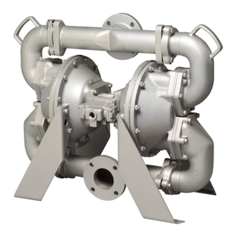
Idex Warren Rupp Sandpiper HDF3-M Service and operating manual

Hikmicro
Hikmicro Mini Series quick start guide
Azbil
Azbil ACTIVAL+ Intelligent Component Series Specifications & instructions

Fluke
Fluke DTX-MFM user manual
Siemens
Siemens A80485-1 quick start guide

Emerson
Emerson 91 Installation and maintenance instructions
Siemens
Siemens Modem Block installation instructions

Stahl
Stahl 9440/22 Series operating instructions
FlexRadio Systems
FlexRadio Systems FLEX-6300 installation guide
Directed
Directed DS4+ installation guide
Kantech
Kantech KT-MOD-OUT16 quick start guide
Carlisle
Carlisle DeVilbiss AG362P Series Service manual
