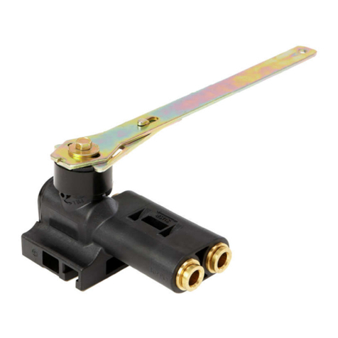
bee 998NG - TAS Product guide

Bedienungs- und Montageanleitung für BEE- Armaturen der Baureihe
998NG - TAS MOP 5 C1
1. Anwendungsbereich
Hinweis:
Die Armatur mit Selbstauslösender thermischer Armaturensicherung ( TAS ) muss gemäß der Anwendung mit
CE-Ident. Nr., nach den Vorschrift der EN 331 und DIN 3586 gekennzeichnet sein.
1.1 Installationsbereich Gase nach G260/1:
EN 331 DIN3586 MOP5 C1 Temperaturklasse -20°C bis +60
DVGW-Reg. Nr. NG-4341BR0017,
1.2 Absperrarmatur gem. der Gasgeräteverordnung EU/2016/426:
CE-Ident.-Nr. CE-0085BR0016
2. Einbau / Montage
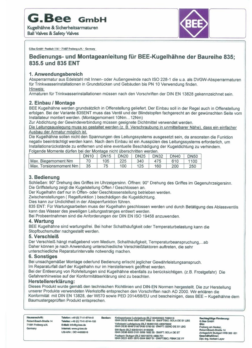
Die Kugelhahn TAS Kombination wird grundsätzlich in Offenstellung geliefert. Der Einbau soll in der Regel
auch in Offenstellung erfolgen. Die Durchflussrichtung ist zu beachten. Die Montage muß fachgerecht nach
Anforderungen der gültigen Installationsrichtlinien (z.B. TRGI) durchgeführt werden. Armaturen mit
ausgelöster TAS dürfen nicht montiert werden. Zur Abdichtung der Gewindeverbindung müssen geeignete
Dichtmittel verwendet werden. (Dichtmittel nach DIN 30660)
Armaturen sollen nicht den Spannungen des Leitungssystems ausgesetzt sein, da ansonsten die Funktion
negativ beeinträchtigt werden kann. Nach dem Einbau ist ein Reinigungsvorgang des Leitungssystems
erforderlich, um Installationsrückstände zu entfernen und eine eventuelle Beschädigung der integrierten TAS
als auch der Kugeldichtung zu verhindern.
Farbanstriche, Isolierungen, Schutzverkleidungen usw. sind unzulässig.
3. Bedienung
Schließen: 90° Drehung des Bedienungshebels im Uhrzeigersinn.
Öffnen: 90° Drehung des Bedienungshebels gegen den Uhrzeigersinn.
Die Stellung der Schaltspindel zeigt die Kugelstellung - Offen / Geschlossen an.
Die Armatur darf nur in Offen- oder Geschlossenstellung betrieben werden.
Zwischenstellungen ( Regelfunktion ) beschädigen die Kugeldichtung.
Dies kann zur Undichtheit in Absperrfunktion führen.
Die Armatur ist vor Umgebungstemperaturen über 60°C ( z.B. Sonneneinstrahlung ) zu schützen,
da die integrierte thermische Armaturensicherung auslösen kann und somit den Durchfluss
verschließt. ( Auslösetemperatur 95°C +/- 5° )
4. Wartung
BEE Armaturen sind wartungsfrei.
5. Warnhinweise
Bei Zerstörung oder Verschleiß eines Kugelhahnteiles, muß die komplette Armatur getauscht werden.
Bauliche Änderungen an Armaturen sind unzulässig.
Die Durchflußmenge muß auf den vorgesehenen Bestimmungszweck abgestimmt sein.
Die Installation muß in Übereinstimmung der örtlichen Installationsbedingungen erfolgen.
Die Installationsanweisungen des Herstellers sind zu beachten.
Bei unsachgemäßer Montage oder/und Bedienung erlischt jeglicher Gewährleistungsanspruch.
Im Reparaturfall darf die Kugelhahn TAS Kombination nur im Herstellerwerk geöffnet werden.
Konformitätserklärung:
Dieses Produkt wurde gemäß den technischen Richtlinien und DIN-EN Normen hergestellt. Das zur
Herstellung verwendete Messing besteht ausschließlich aus Legierungen nach DIN EN 12420 und erfüllt die
Vorschriften des DVGW Regelwerkes. Wir erklären die Konformität mit den angewandten Regelwerken und
bescheinigen, daß BEE –Kugelhähne mit integrierter TAS dem baumustergeprüften Produkt entsprechen.

Konformitätserklärung
gemäß Anhang 4 der Druckgeräterichtlinie 2014/68/EU und Anhang 3 der GAR EU/2016/426
Hersteller: G. Bee GmbH
Robert-Bosch-Straße 14
D-71691 Freiberg a. N.
Beschreibung:
Kugelhahn mit eingangsseitig integrierter thermischer Armaturensicherung „TAS“,
zur Absperrung und thermischer Absicherung nach geschalteter Objekte in der
Gasinstallation. (Druck haltendes Ausrüstungsteil)
Angewandte Konformitätsbewertungsverfahren:
PED: Modul H ( Umfassende Qualitätssicherung ) benannte Stelle TÜV Rheinland (CE-0035)
GAR: EU/ 2016/426 Baumusterprüfung benannte Stelle DVGW (CE-0085)
Angewandte Regelwerke:
Einteilung
Regelwerke
Auslegung
AD2000 –A4, DIN 3840
Gewindeanschluß
ISO 7-1, DIN EN 10226-1
Anwendungsbedingte
Regelwerke
DIN-EN-331-2016, DIN3586, PED 2014/68/EC, GAR EU/2016/426
Prüfungen
DIN3230-5, DIN EN 12266-1
Elastomere
DIN EN 549, DIN EN 682
Kennzeichnung
DIN EN 19, PED 2014/68/EU, GAR EU/2016/426, DIN EN331, DIN 3586
Wir erklären, daß das Produkt mit der Richtlinie 2014/68/EU und EU/2016/426 übereinstimmt und oben
genannten Konformitätsbewertungsverfahren unterzogen wurde.
Risikoanalyse:
Der Kugelhahn mit eingangsseitig integrierter TAS ist auf Belastungen ausgelegt, die der beabsichtigten
Verwendung und anderen nach vernünftigem Ermessen vorhersehbaren Betriebsbedingungen angemessen
ist. Insbesondere sind folgende Faktoren zu berücksichtigen.
Druckbelastung: Die Druckbelastung muß in dem angegebenen Druckbereich liegen.
Gegen eine Drucküberschreitung sowie Druckschläge sind geeignete Maßnahmen zu ergreifen.
Zu Prüfzwecken kann die Armatur mit 1.5xNenndruck beaufschlagt werden.
Temperaturbelastung:
Die Umgebungstemperatur darf 60°C nicht überschreiten, da ansonsten die thermische
Armaturensicherung auslöst und den Durchfluß absperrt. Auslösetemperatur 95°5°
Ausgelöste TAS müssen erneuert werden.
Beständigkeit gegenüber dem Medium: Alle Werkstoffe sind auf dem Datenblatt aufgeführt.
Die chemische Verträglichkeit muß sichergestellt sein.
Reaktionskräfte: Reaktionskräfte und –Momente im Zusammenhang mit Trageelementen, Rohrleitungen
Befestigungen usw. dürfen die in EN331 aufgeführten Momente nicht überschreiten.
Durch Auslegung und Bau muss folgendes sichergestellt sein:
Der Gefahr einer Überbeanspruchung durch unzulässige Bewegung oder übermäßige Kräfte z.B. an
Armaturen ist durch Unterstützung, Befestigung, Ausrichtung in geeigneter Weise vorzubeugen.
Bei gasförmigen Fluiden die Kondensflüssigkeiten bilden sind geeignete Einrichtungen zur Entwässerung zur
Vermeidung von Schäden durch Wasserschlag und Korrosion vorzusehen. Die Gefahr von
Ermüdungserscheinungen durch Vibration des Rohrleitungssystems sind gebührend zu berücksichtigen.
Freiberg a.N. 25.01.2018 Michael Boger Konstruktion / Entwicklung
Unterschrift

Operating and Assembly Instructions for BEE valves
series 998NG - TAS MOP 5 C1
1. Field of Application
Note:
The valve with automatic thermal release (TAS) must be marked according to the standards EN 331 and DIN
3586 with CE Identification No. or National Registration No..
1.1 Installation fields of gases in accordance with G260/1:
EN 331 DIN3586 MOP5 C1 temperature range from -20°C to +60°C
DVGW Reg. No. NG-4341BR0017
1.2 Shut-off valves in accordance with the Gas Appliance Regulation EC/2016/426:
CE Identification No. CE-0085BR0016
2. Installation / Assembly
The ball valve TAS combination is always supplied in the open position.
In general, they are to be installed in the open position. The direction of flow must be adhered to.
The ball valve must be assembled professionally in accordance with the present installation regulations
(f.ex. TRGI ). Valves with a tripped TAS must not be assembled.
Appropriate agents must be used to seal the threaded joint (sealing agents in conformity with DIN 30660)
Valves are not subject to the stresses of the pipe system, as their function may otherwise be impaired.
After installation, the pipe system must be flushed out in order to remove any residual matter and to prevent
possible damage to the integrated TAS and the ball seal.
Coats of paint, insulations and protective clothing etc., are not allowed.
3. Operation
To close: Turn the operating lever 90° clockwise.
To open: Turn the operating lever 90° anti-clockwise.
The position of the spindle indicates the ball position - Open / Closed.
The valve may only be operated in the Open or Closed position.
Intermediate positions (control function) can damage the ball seal.
This can cause leakage in the shut-off function.
The valve must be protected from ambient temperatures above 60°C (e.g., sun rays), since this may trigger
the thermal release and thus shut off the flow. (Trigging temperature 95°C +/- 5°)
4. Maintenance
BEE valves are maintenance-free.
5. Warnings
In case of destruction or wear of a ball valve part, the complete valve must be replaced.
Structural changes to valves are not permitted.
The flow rate must be matched to the intended purpose.
Installation must be in accordance with local installation conditions.
The installation instructions of the manufacturer are to be observed.
Incorrect assembly and/or operation will invalidate the right to make claims under the warranty.
In the event of repair the ball valve TAS combination may only be opened in the manufacturer's plant.
Declaration of the Manufacturer:
This product has been manufactured in accordance with the technical guidelines and DIN-EN standards.
The brass materials used to manufacture our products comply with the regulations according to DIN EN
12420. We hereby declare that the valves with integrated TAS conform to the applicable DVGW regulations
and confirm that BEE ball valves correspond to the design type-tested product.

Declaration of conformity
in accordance with Appendix 4 of the Pressure Equipment Directive 2014/68/EC and GAR EC/2016/426
Manufacturer: G. Bee GmbH
Robert-Bosch-Straße 14
D-71691 Freiberg a. N.
Description:
Ball valve with integrated "TAS" thermal release on the supply side for shut-off and thermal protection of
objects connected on the load side in the gas installation. (pressure-maintaining plant component )
Applicable conformity evaluation procedure:
PED: Module H (Quality Assurance) notified body TÜV Rheinland (CE-0035)
GAR EC/20165/426: Type approval notified body DVGW (CE-0085)
Applicable rules:
Classification
Regulations
Construction
AD2000 –A4, DIN 3840
Threaded connection
ISO 7-1, DIN EN 10226-1
Application-specific
regulations
DIN-EN-331-2016 DIN3586, PED 2014/68/EC, GAR EC/20165/426
Tests
DIN3230-5, DIN EN 12266-1
Elastomers
DIN EN 549, DIN EN 682
Marking
DIN EN 19, PED 2014/68/EU, GAR EC/20165/426, DIN EN331, DIN 3586
We hereby declare that the product conforms to Directive 2014/68/EC and GAR EC/20165/426 and has
undergone the above-mentioned conformity evaluation procedure.
Risk analysis:
Ball valves with integrated TAS on the supply side are designed for loads which are appropriate to the
intended use and other foreseeable operating conditions that are considered to be reasonable. The following
factors in particular must be taken into consideration.
Pressure load: The pressure load must not exceed the pressure range specified.
Appropriate measures must be taken to avoid excess pressure or pressure impacts.
For the purpose of testing the valve can be impacted with 1.5x nominal pressure.
Temperature stress:
The ambient temperature may not exceed 60°C, since otherwise the thermal release is tripped and shuts off
the flow. Tripping temperature 95°5°
Once tripped, TAS's must be replaced.
Resistance to the medium: All the materials are listed on the data sheet.
Their chemical compatibility must be guaranteed.
Reaction forces: Reaction forces and moments in connection with supporting elements, pipeline fixings, etc.,
may not exceed the moments specified in EN331.
Design and construction must guarantee the following:
Appropriate methods of support, fixing and alignment must be used to prevent the risk of overstressing by
e.g., inadmissible movement or excessive force on valves.
In the case of gaseous fluids that form condensate, suitable dehydration facilities must be provided to prevent
damage caused by water shock and corrosion. The risk of fatigue phenomena caused by vibration of the
pipeline system must be given due consideration.
Freiberg a.N. 25.01.2018 Michael Boger design and development
Signature
Table of contents
Languages:
Other bee Control Unit manuals
