beevision 183 User manual

BeeVision 183
Version 1.1
USER
MANUAL

1
CONTENTS
1.Preface ....................................................................................... 2
2.Description of The Product and Intended Use ........................... 3
2.1 Important Information ........................................................ 3
3.General Information ................................................................... 3
3.1 Overall Dimensions ............................................................. 4
3.2 Main Parts ........................................................................... 5
4.Using the Device ......................................................................... 7
4.1 Turning On/Off .................................................................... 8
4.2 Measurement Area ............................................................. 9
4.3 Volumizer .......................................................................... 10
4.4 Operation .......................................................................... 17

2
1. Preface
This document describes the usage of the BeeVision 183
dimensioning and weighing system. Permission must be obtained
from 3DTİM Elektronik A.Ş. to copy, reprint and translate this
document in whole or in part. This manual may not be published, in
whole or in part, or used without authorization for competitive
purposes. We reserve the right to make technical changes for
improvement.
This device can only be used for dimensioning and weight
measurements of 800x800x600 mm (WxDxH) opaque objects with a
maximum weight of 20 kg. Any use other than this purpose is
deemed illegal and constitutes a misuse of the machine. If it is used
in this way, all responsibility will be on the user.
BeeVision 183 is covered by a 1-year warranty. Malfunctions
resulting from user error or the use of the device not in accordance
with the user manual are not covered by the warranty.

3
2. Description of The Product and
Intended Use
BeeVision 183 is an industrial product used for dimensioning
and weighing. This device is designed for dimensioning and weighing
measurements of 800mmx800mx600mm (WxDxH) opaque loads
with a maximum weight of 20 kg. Provides flexibility in warehouses
by becoming portable with the cart shipped with the device.
Make sure that the feet that allow the device to be
attached to the vehicle from below are attached.
2.1 Important Information
• The maximum weight capacity is 20 kg.
• The device may not work properly if the slides that provide
the device movement are damaged.
• If the encoder in the moving parts is disconnected from the
gears, the device cannot measure correctly.
• BeeVision 183 cannot measure transparent objects such as
glass.
3. General Information
4
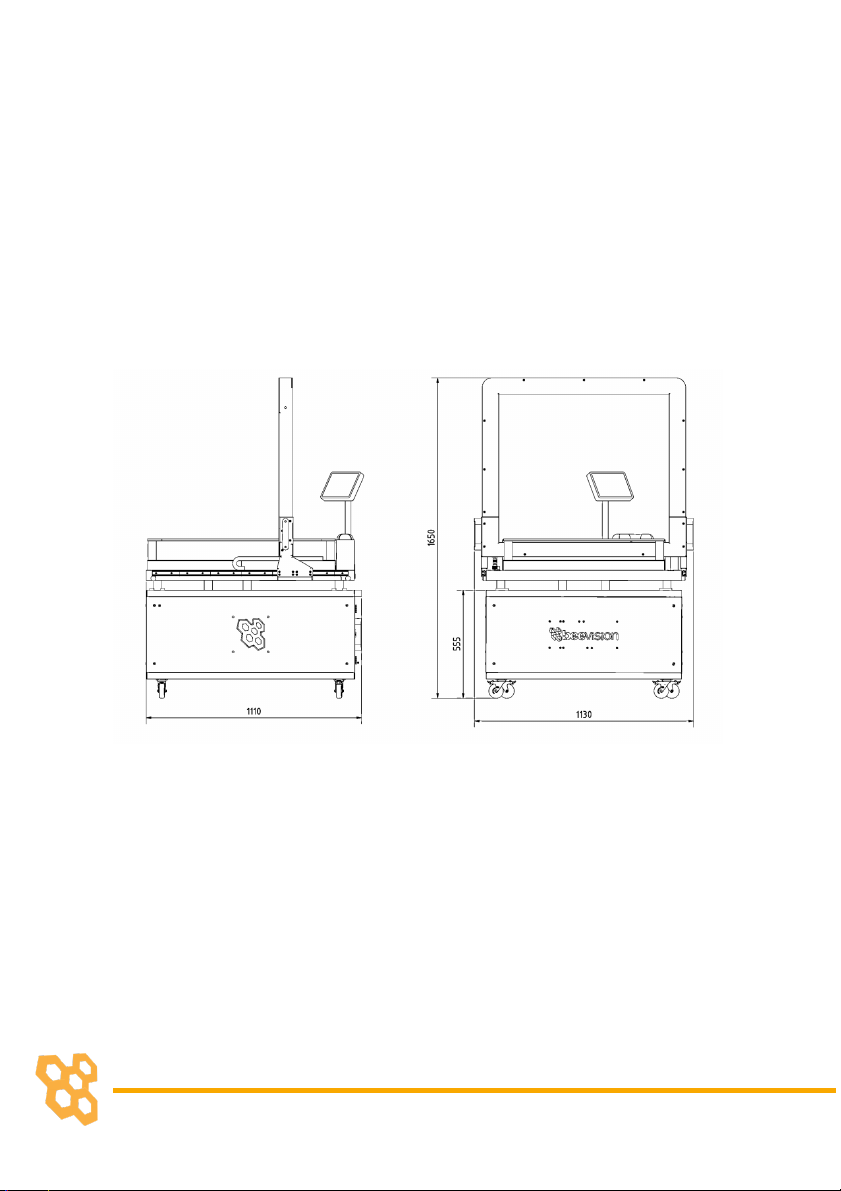
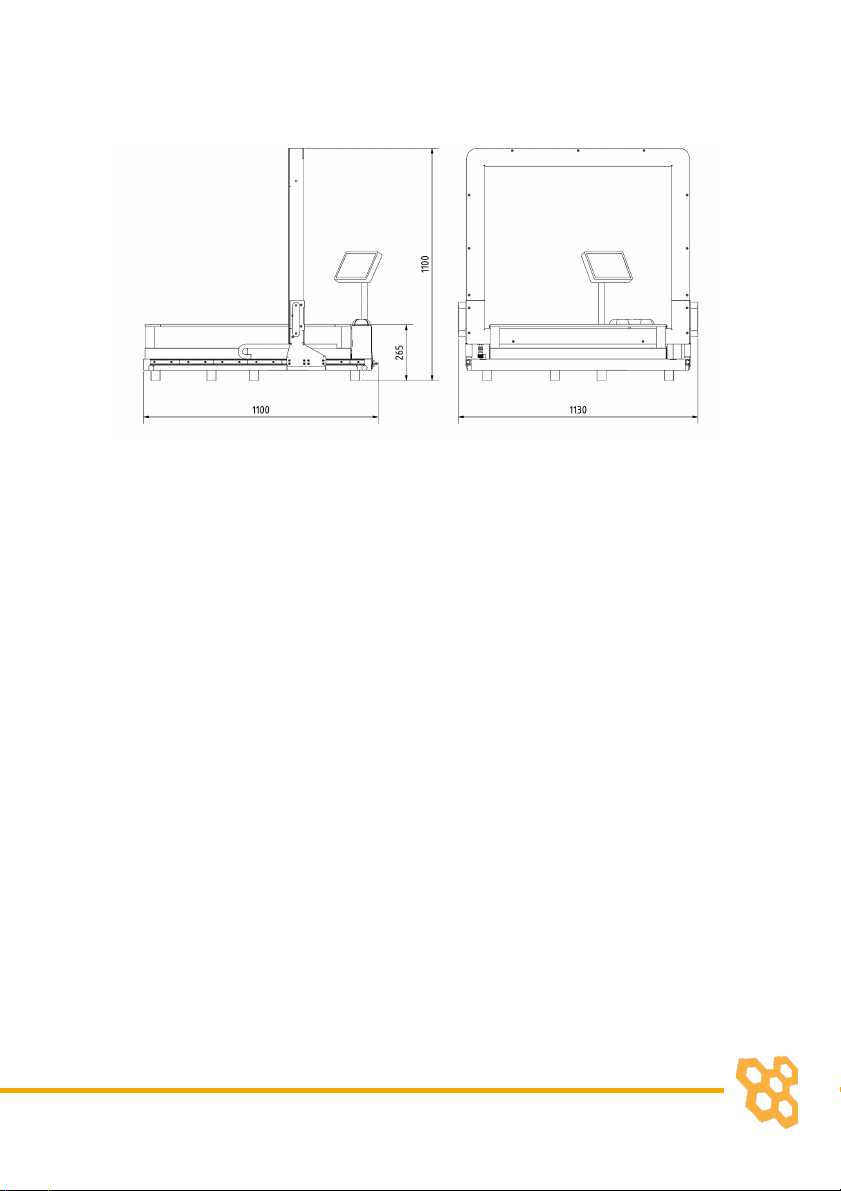
3.1 Overall Dimensions
The dimensions of the BeeVision 183 without cart are
1100x1100x1015 mm. The dimensions of the device together with
the car are 1100x1100x1570 mm. The specified dimensions are
shown in the figure below. (units are in mm)
Figure 3. 1
5
Figure 3. 2
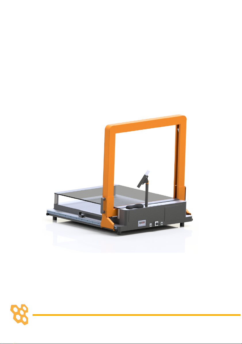
3.2 Main Parts
Scanner: It is the orange group with handles. It moves with help of
linear guideways located on both sides of the device. The Scanner
allows the size of the object to be measured with an accuracy of 0,5
mm. Therefore, it should be used sensitively.
Weighing: It consists of the metal table where glass and legs are
joined. It measures the weight of the load placed on it with an
accuracy of 5 grams.
Monitor: This touchscreen monitor displays device controls,
measuring and weighing results.
Barcode Reader: It allows the product dimensions to be transferred
directly to the system by reading the barcodes of the products to be
measured
6
Indicator: The indicator, which is directly connected to the scale,
allows the weighing to be converted into numerical values.
Calibration of the balance is done from this section. The indicator is
located on the back of the device.
Rack Gear and Pinion: It is another element that allows the
measurement of the object to be taken. Any jamming will adversely
affect measurement accuracy.
Cart: It allows the device to be moved manually.
Figure 3. 3

7
USB 3.0 Port: There is one USB 3.0 port on the backside of the device.
In this way, users will be able to receive data from this port with the
help of a flash memory.
Ethernet Port: To communicate with any computer or a local server
for the data transfer.
Figure 3. 4
Rotary Switch: It is used to turn the system off and on. When the
switch is in position 0, all components of the system are turned off.
Wireless Antenna: Antenna, which is mounted on the dimensioner,
performs data transfer by establishing wireless communication with
a wireless modem device/PC.
4. Using the Device

8
4.1 Turning On/Off
When the power cord is inserted into the power port and
given mains voltage, turn the power switch shown in Figure 3. 4 to
position 1 and the system will be ready for use. The input mains
voltage BeeVision dimensioner must be at an interval between 100V-
240V and 50Hz-60Hz.
To turn off the device, simply unplug the power cord or turn
the power switch to ‘0’ state.
The mouse cursor is by default hidden in Volumizer UI. If you
would like to connect a mouse and a keyboard, you can
enable/disable the mouse cursor with Ctrl+Shift+M combinations on
your keyboard.
Please refer to the Software Guide for more
details on how to integrate BeeVision into your
system.

9
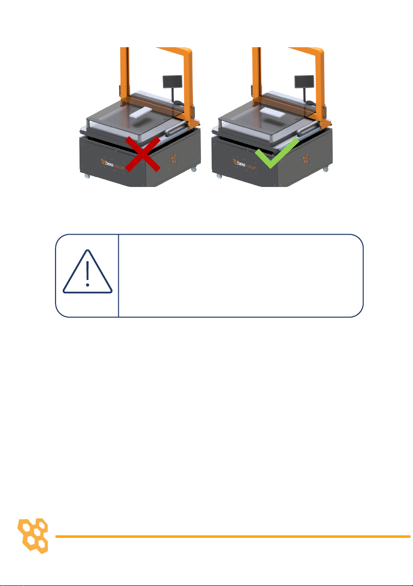
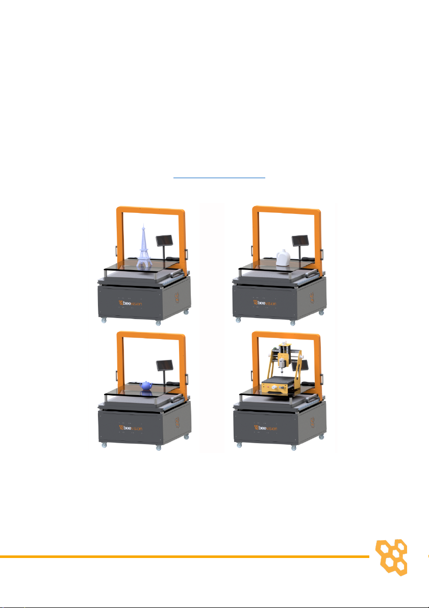
4.2 Measurement Area
For the device to measure the object, the object must be
placed on the glass.
There is a color transition on the glass to make sure the object
does not stick out. Objects that overflow onto the painted part of the
glass cannot be measured.
Figure 4. 1
For better measurement, you have to put the
object horizontally. Also, the bigger dimension of
the object has to be perpendicular to the linear
channels.
10
Make sure that the dimensions of objects are less
than 800x800x600 (WxDxH) mm. Otherwise, the
object will overflow into the painted part of the
glass and correct measurement will not be
achieved.
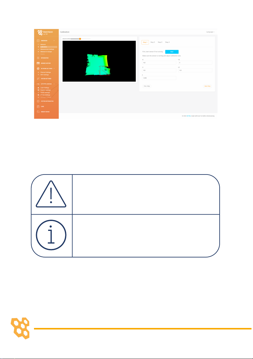
4.3 Volumizer
Volumizer is the software installed in the BeeVision
dimensioners that enables users to control the device, perform
calibration and measurements. It has a graphical user interface (GUI)
that can be used when BeeVision is connected to a monitor.

11
Figure 4. 2
It also has a web-based user interface (Web UI) that can be
accessed from a browser with the following address:
http://IP_address_of_device. The officially supported browser is
Google Chrome.
12
Figure 4. 3
If you use a different browser than Google Chrome,
some functions may not work as expected.
Users can navigate to the pages from the main
menu as shown in Figure 4. 2 and Figure 4. 3.

13
Following pages are included in Volumizer GUI and Web UI:
Brings up dimensioning
submenu
Dimension
Measure
Trigger measurement and
display results
Perform calibration and view 3D,
2D, and model data
Calibration
Measurement
Settings
Change measurement settings
Measurement in
Groups
Perform measurements in
groups and save results to a
remote address as an XML file
per group

14
Source
Merge 3D data with a slave,
remote BeeVision device
Brings up the barcode decoding
submenu (might be disabled
depending on the model)
Decode
Integration
Change result sharing options
Change Ethernet and Wi-Fi
settings
Network Settings
Change system settings such as
language, time, date, and device
operation mode
System Settings
Brings up the external devices
submenu
External Devices

15
Scale Settings
Change scale connection
settings
Scanner Settings
Change handheld and fixed-
mount barcode scanner
connection settings
Printer Settings
Change label printer settings
Conveyor Settings
Change conveyor and PLC
connection settings (might be
disabled based on the model)
Ip Cam Settings
Change IP camera settings
(might be disabled based on the
model)
Browse History
Browse previous measurement
results

16
View information about the
system such as model name,
certification status, SW
checksum, etc.
System Information
Restarts the device.
Reboot
View system log and parameter
changelog.
Logs
GUI Navigation Icons:
Opens up the previous upper menu page.
Opens up the main menu page.
17
4.4 Operation
BeeVision 183 dimensioning system is delivered as pre-
calibrated. If there is nothing wrong with delivery and installation,
there is no need to recalibrate the device.
The measurement area is to the border of the painted side
of the glass. Read the Measurement Area chapter if you need
support in this case.
Figure 4. 4
Steps of Measurement

18
• To perform a measurement, an object must be placed into
the measurement area and measurement and weighing
should be triggered by moving the scanner.
• When the user moves the scanner to measure, it must be
moved along the entire object.
Figure 4. 5

19
During the measurement, there must be only one
object in the measurement area.
No part other than the scanner should be touched
to accurately measure the weight of the item.
• Whether the user scans the barcode just before or right after
weighing, the product measurement data will reach the
system directly via Wi-Fi.
• The user can view the results on the touch monitor at this
stage.
• The user can take the object and can move on to measure
the next one.
Objects can be placed to any location on the
measurement area to measure.
For more information, please contact us.
Table of contents
Other beevision Measuring Instrument manuals


Popular Measuring Instrument manuals by other brands


Woodley
Woodley InSight V3 PLUS Operator's manual

Keysight Technologies
Keysight Technologies N6705C Operating and service guide

CYP
CYP CPHD-V4 Operation manual

Teledyne Lecroy
Teledyne Lecroy DL03-ISO user manual

Spirax Sarco
Spirax Sarco ILVA20 Installation

Qstarz
Qstarz Explore 2000 Quick installation guide

DeFelsko
DeFelsko PosiTest PC instruction manual

getemed
getemed PhysioMem PM 100 4G Instructions for use

PR electronics
PR electronics 5714 product manual

iLine microsystems
iLine microsystems microINR Instructions for use

Trotec
Trotec BP21 operating manual

PCB Piezotronics
PCB Piezotronics 357B45 Installation and operating manual