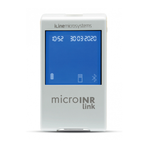
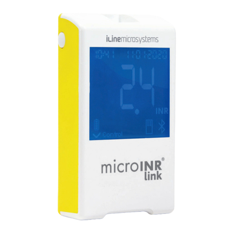
iLine microsystems microINR User manual

friendly
technology
Instructions for use

No part of these instructions for use or the products it describes may be reproduced by any means or in any form without prior consent in writing from iLine
Microsystems.
The information contained in these instructions for use was correct at the time of printing. However, iLine Microsystems reserves the right to introduce
changes to the specifications, equipment and maintenance procedures of the system at any time, without prior notification. Any substantial changes will be
added to the next revision of these instructions for use. In case of conflict between the information of the instructions for use of the microINR Meter and the
microINR Chip, the information contained in the instructions for use of the microINR Chip will have priority.

01
For monitoring of oral anticoagulation
treatment based on Vitamin K
antagonist drugs.
CONTENTS
English
microINR Meter
INTRODUCTION
INTENDED USE
BEFORE STARTING TO USE THE
microINR® SYSTEM
Safety information
ORAL ANTICOAGULANT THERAPY
INR and Prothrombin Time
MEASURING PRINCIPLE
microINR® SYSTEM
DESCRIPTION OF THE microINR® KIT
PARTS OF THE microINR® METER
CHARGING THE microINR® METER
SETTING THE TIME AND DATE
PATIENT IDENTIFICATION (OPTIONAL)
QUALITY CONTROL
CONDUCTING THE TEST
PREPARING THE NECESSARY MATERIALS
MEASUREMENT PROCEDURE
Turning the Meter On
Inserting the Chip
1.
1.1
1.2
1.3
1.4
2.
2.1
2.2
2.3
2.4
2.5
2.6
3.
3.1
3.2
Modes of Use
Conducting the Test
Test Result and Assay End
Turning the Meter Off
OBTAINING AND APPLYING THE CAPILLARY
BLOOD SAMPLE
INTERPRETING THE RESULTS
LIMITATIONS OF USE
MEMORY AND DATA EXTRACTION TO
A COMPUTER
CLEANING AND DISINFECTING THE
microINR® METER
ERROR GUIDE
ADDITIONAL INFORMATION
SPECIFICATIONS
CE DECLARATION OF CONFORMITY
WARRANTY
TECHNICAL SERVIC
SYMBOLS
GLOSSARY
9
9
10
10
11
12
12
13
13
15
16
16
16
16
16
17
18
3.3
3.4
3.5
4.
5.
6.
7.
7.1
7.2
7.3
7.4
7.5
7.6
2
2
2
2
3
3
4
5
5
6
6
6
7
7
8
8
8
8
8

02
1.1 INTENDED USE
The microINR system is intended to monitor oral
anticoagulation therapy (OAT) with vitamin K antagonist drugs.
The microINR system determines quantitative prothrombin
time (PT) in INR (International Normalized Ratio) units with
fresh capillary blood performed by fingersticking.
The microINR system is a medical device for in-vitro
diagnostics intended for professional and self-testing use.
1.2 BEFORE STARTING TO USE THE
microINR® SYSTEM
The microINR Meter is intended to be used exclusively with the
microINR Chips manufactured by iLine Microsystems.
Before starting to use the microINR system, read these
instructions for use completely, as well as the instructions for
use of the microINR Chip. Also, do not forget to read the
instructions for use of the lancing device and lancets used to
obtain the capillary blood sample.
Keep these instructions for use near the microINR system and
refer to them if you have any questions about proper
operation of the system.
Users of the microINR system (patients and healthcare
professionals) must receive proper training before
starting to use the system.
Before starting to use the microINR system, verify the
compatibility between the soware version of your Meter and
the reference of the Chips you are going to use.
REF SOFTWARE VERSION*
CHA0025AA All soware versions
CHB0025AA >07:03
*The soware version appears at the top of
the display, immediately aer turning the
Meter on. If you cannot read the version,
repeat the attempt by turning the Meter off
and on again.
Safety Information
General Safety Warnings
Throughout these instructions for use you will find safety
warnings and information on the correct use of the microINR
system:
This warning symbol indicates a possibility of danger
which could result in death, injury or damage of the
patient or user if the procedures and instructions for
use are not strictly followed.
This precaution symbol indicates the possibility of
deteriorating or damaging the equipment and losing
data, if the procedures and instructions for use are not
strictly followed.
1. INTRODUCTION

03
Important information regarding the correct use of the
system that does not affect the safety of the patient or the
integrity of the device is displayed over a blue background.
Infection Risk Control on Multi-Patient Tests
•Healthcare professionals must wear gloves during the entire
process of the test.
•A separate lancet or lancing device should be used for each
individual.
•Used Chips, lancets and gloves might be source of infection.
Dispose them in accordance with local regulations to prevent
infections.
•Also, comply with your centre’s internal hygiene and safety
regulations.
There is a potential risk of infection. The healthcare
professionals using the microINR system on several
patients must take into account that all objects that
come into contact with human blood are a possible
source of infection. (See: National Committee for
Clinical Laboratory Standards: Protection of Laboratory
Workers from Instrument Biohazards and Infectious
Disease Transmitted by Blood, Body Fluids and Tissue.
Approved Guideline, NCCLS document M29-A, 1997).
Electromagnetic Compatibility and Electrical Safety
The microINR system complies with electromagnetic
compatibility requirements according to IEC 61326-1 and
61326-2-6 standards.
Do not use the microINR system near sources of
intense electromagnetic radiation, as this could
interfere with its correct operation.
The microINR system complies with electrical safety
requirements according to standards IEC 61010-1 and IEC
61010-2-101.
Do not connect the Meter to computers that do not
comply with standard IEC 60950.
The Meter must be disposed of as indicated in the WEEE
Directive (Waste Electrical and Electronic Equipment
2012/19/UE).
1.3 ORAL ANTICOAGULANT THERAPY
Oral anticoagulant therapy is given to patients to prevent
thromboembolic events such as vein thrombosis, pulmonary
embolism or those linked to atrial fibrillation or replacement of
heart valves.
The treatment entails the need to monitor and adjust the
doses periodically for each patient based on a blood test.
Depending on the cause for oral anticoagulant therapy a
therapeutic range is defined for each patient meaning the
value of the test should lie within that range.
INR and Prothrombin Time
The activity of oral anticoagulants is monitored by measuring
the prothrombin time (PT) in seconds, which is the time it

1.4 MEASURING PRINCIPLE
The technology used by the microINR system is based on the
microfluidics of the microINR Chip, which allows storing,
dosing, moving and/or mixing small volumes of liquids to
perform a chemical reaction.
The microINR Chips contain two channels, one for
measurement and the other for control. An image of the Chip
is shown below:
Each channel consists of a micro-reactor that contains the
reagent and a microcapillary where the INR is determined. The
reagent used in the measuring channel contains human
recombinant thromboplastin and the reagent in the control
channel contains recombinant thromboplastin and human
coagulation factors to normalize the patient’s blood.
The blood is applied on the Chip through the entry channel,
separated into two channels and mixed with the reagents
contained in each micro-reactor. The coagulation cascade is
triggered instantly. When blood coagulates, its viscosity
04
takes for a fibrin clot to form. Thromboplastin is used as a
reagent to calculate the prothrombin time (PT). Depending on
the nature of this reagent and the equipment used variations
on the PT results are to be expected.
Therefore, the WHO recommended a system standardisation
method in 1977. Prothrombin time values are converted into
INR values, International Normalized Ratio, using the following
equation:
Where PT is the prothrombin time obtained in the test, MNPT
is the mean normal prothrombin time and ISI the international
sensitivity index corresponding to the thromboplastin. The
values of the MNPT and ISI parameters come from clinical
calibration studies.
The pharmacological activity of vitamin K-antagonist
oral anticoagulants can be modified by other drugs;
therefore, you should only take the medicines
prescribed by your physician.
Certain liver diseases, thyroid disorders and other
diseases or conditions, as well as nutritional
supplements, medicinal herbs or changes in diets can
affect the therapeutic activity of oral anticoagulants
and INR results.
INR =PT ISI
MNPT
( )
ENTRY CHANNEL
MICROREACTORS
DATAMATRIX
MICROCAPILLARY
CHANNELS
CONTROL CHANNEL MEASURING
CHANNEL

05
increases, which results into a change in blood flow behaviour.
The Meter captures the position of the sample by means of a
Machine vision system and the position is transformed
mathematically into speed and acceleration curves, from
which an INR value is obtained.
Calibration
Each batch of microINR Chips has been calibrated against a
reference batch of human recombinant thromboplastin traced
to International Reference Thromboplastin of the World Health
Organization1.
These calibration values (ISI and MNPT) are encoded in the
printed Datamatrix of each microINR Chip. Therefore, every
test is automatically and individually calibrated eliminating
any risk of human error.
(1). Expert committee of the WHO on biological normalization.
Report forty-eight. Geneva, World Health Organization, 1999
(WHO technical report series No. 889)
2.1 DESCRIPTION OF THE microINR® KIT
The microINR kit includes:
- Case
- microINR Meter
- Charger
- Power adapter
- Mini USB cable
- microINR Data Extraction Soware CD
- Instructions for use of the microINR Meter
- Quick guide
- Error guide
- Lancing device (exclusive for Reference Kit KTA0001XX)
- Lancets (exclusive for Reference Kit KTA0001XX)
microINR Chips are sold separately.
Always carry the Meter inside its case.
2. microINR® SYSTEM

2.2 PARTS OF THE microINR® METER
2.3 CHARGING THE microINR® METER
The Meter uses a lithium battery that can be recharged
through the mini USB connection on the top of the Meter.
Do not place the device in a way that handling the
disconnection element is made difficult.
The recommended charging time is approximately 3 hours.
06
Charge the battery completely before using the Meter
for the first time.
Do not open or manipulate the Meter.
Do not pierce or burn the battery.
Do not change the battery. The manufacturer will not
warranty Meters that have been opened.
If opening the Meter is necessary, the equipment must
be sent to the manufacturer.
Use only the supplied USB cable and wall power
adapter provided by the manufacturer or you may
damage the Meter.
2.4 SETTING THE TIME AND DATE
• Date format: DD/MM/YY; Time format: 24 hours.
•Press and hold the left and right buttons (E and M) at the
same time for 10 seconds until the time fields flash.
•Press the left button (E) to set the hour.
•After selecting the right time, press the right button (M) and
set the minutes.
•After selecting the minutes, press the right button (M) again
and the date fields will start flashing.
•Use the left button (E) to select the correct day.
•When you reach the correct day, press the right button (M) to
set the month. Use the left button (E) to select the correct month.
•When you reach the correct month, press the right button (M) to
MINI USB CONNECTION
EXIT (E) BUTTON
BOTÓN
MEMORY (M)
CHIP
INSERTION
AREA
DISPLAY

07
set the year. Use the left button (E) to select the correct year.
•After setting the month, time and date, press the right button
(M) again to save your settings.
Conducting a test without setting the date correctly
might cause a non-detection of expired Chips (E02).
2.5 PATIENT IDENTIFICATION (OPTIONAL)
To identify the patient (PID), take the following steps before
conducting a test:
• Hold the right button while inserting a Chip and release it
afterwards. Upon releasing the button, “PID” and a 24
alphanumeric field will be displayed, to fill in.
• To enter the characters corresponding to the PID:
- The first field will flash when selected.
- To enter the first character, press the le button until you
reach the desired character.
- Validate the character with the right button and go to the
next field.
- Repeat the previous steps until you reach the last field.
- Aer accepting the last field, the first field is automatically
selected in case you want to correct any characters.
- To confirm the ID entered and go back, hold the right
button for 3 seconds.
While you are entering the PID, if one minute elapses
without pressing any buttons, an E01 message will be
displayed.
When consulting the results on the Meter, the result of a test
(INR or error message) is displayed along with its
corresponding PID, date and time. When exporting the
microINR results to a PC, the PID will be exported as one more
piece of test information.
2.6 QUALITY CONTROL
Internal quality control
Meter performance is automatically checked when the system
is turned on.
Integrated and independent on-board quality controls
Level 1 – Pre-test
• Chip integrity check
•Correct insertion check
•Automatic system calibration and rejection of expired
Chips
Level 2 - Measuring channel
• Analytic verification performed on the measuring channel that
identifies failures when processing the sample during the test,
as well as proper pre-analytical treatment of the sample.

08
Level 3 - Control channel
•Control channel provides highly controlled clotting times.
System reliability is assured when control clotting time lies
within a pre-defined range.
PROFESSIONAL USE:
Liquid control:
The microINR system has a number of on-board quality
control functions integrated into the Meter and the Chip and
therefore there is no need to run quality control tests with
liquid quality controls. However, iLine Microsystems has
available an optional liquid quality control for the microINR
system. This control is provided to help meet the regulatory
requirements applicable to your facility. Contact your local
distributor.
3.1 PREPARING THE NECESSARY MATERIALS
• microINR Meter
•microINR Chips (not supplied)
•Fingersticking material
- Professional use: disposable lancets (not supplied)
- Self-testing: lancing device and lancets (exclusive
Reference Kit KTA0001XX)
• Skin cleaning material (not supplied)
3. CONDUCTING THE TEST
Always use CE marked lancing devices and lancets.
3.2 MEASUREMENT PROCEDURE
Turning the Meter On
The Meter can be turned on:
- By inserting the Chip: - By pressing any button:
Inserting the Chip
Verify the expiry date and the stored conditions of the Chip
before conducting the test.
• Open the pouch. Hold the Chip by the yellow part and so the
“microINR” inscription can be read correctly. Insert the Chip
into the slot and push it until it stops. Make sure the Chip
has reached the end.

Conducting the Test
•Once the Chip is inserted, the
Meter will perform the quality
controls mentioned in section
2.6 of these instructions for
use. After conducting the
aforementioned quality controls
prior to the test, the “control”
symbol will light up. If the first level of quality control is not
passed, an error message will be displayed on the screen of
the Meter.
• The Chip begins to flash and
heats up until it reaches the
proper temperature. Once this
temperature is reached:
- The device emits an audible
signal (beep).
- The drop symbol begins to
flash on the display.
- A count down appears (80s).
- The Chip emits a steady light.
• Perform the fingerstick (see section 3.3 of these instructions
for use).
•Make sure to obtain a spherical, properly sized drop.
•Apply the drop of blood on the Chip immediately, in contact
with the entry channel, without resting the finger on the Chip.
•The Meter will emit a beep when it detects the sample for
the test and the drop symbol will stop flashing.
09
If the pouch of the Chip is open,
damaged or the film of the Chip is
removed, please, dispose of the
Chip and use a new one.
Modes of Use
The microINR system provides two
application modes of the sample:
iLine Microsystems only recommends the option of approaching
the Meter to the sample for users who are experienced in
conducting INR assays with the microINR system.
- Approaching the
sample to the Meter.
- Approaching the Meter to
the sample. COUNTDOWN

10
•After the beep, gently move the finger away and wait until
the INR results are displayed on the screen.
If you apply the sample and no sound is emitted, this means
that there is not enough sample volume. Remove the Chip and
repeat the test with a new Chip. Ensure that the size of the
drop is enough and the entry channel is not blocked when
placing it.
Never perform the fingerstick before the start of the
countdown.
Do not touch the Chip’s entry channel with the finger
while inserting the sample.
Do not touch the Chip or add more blood during the test.
Keep the Meter away from direct sunlight during the test.
Do not shake or drop the Meter. If the Meter is dropped
or gets wet and the frequency of errors messages
increases, contact your distributor.
Test Result and Assay End
• The measurement is performed and the Meter displays the
result in INR units or an error message.
Error messages are displayed as a letter
“E” followed by a number. If an error
message is shown, follow the steps in
the “Error Guide” section”.
If the message E08 appears, do not attempt a new
test and proceed to charge the Meter.
•Remove the Chip, holding it from both
sides.
The used Chips, lancets and gloves
might be source of infection. For
healthcare professionals: dispose
the materials according to your
institution´s infection control policy
and the appropriate local regulations.
For self-testing patients: you can
dispose all the materials in your garbage bin. Discard
the used lancets with care to prevent injuries.
Turning the Meter Off
There are two ways to turn the Meter off:
•The Meter turns off automatically after 5 minutes of
inactivity.
•Press the left button (EXIT) to turn the
Meter off, holding it for 3 or 4 seconds.
If you don’t remove the Chip before
turning the Meter off, the results will
not be stored.
The Meter cannot be turned off while
connected to the power supply or to a
computer with the USB cable.

• You can use any finger for the
fingerstick. The recommended
site is the one shown on the
following image.
•Place the lancing device firmly
against the finger and press the
button. Press the base of the
finger gently until a drop of
blood forms. Do not press the
fingerstick site excessively or let
the drop of blood smear on
the finger. Before placing the
drop of blood on the Chip,
make sure that it has the
right size and a spherical
shape. Right size means that
it will provide a remnant.
Pressing the fingerstick
site may accelerate the
process of coagulation
or release of interstitial fluid into the sample which
may cause incorrect results.
•Apply the drop on the Chip immediately, in contact with the
entry channel.
11
3.3 OBTAINING AND APPLYING THE CAPILLARY
BLOOD SAMPLE
The steps to obtain and apply a capillary blood sample
correctly are detailed below:
• Read the instructions of the
fingersticking devices.
• Hands should be warmed
before conducting the
fingerstick. You can achieve this
by different means: keeping
hands below your waist,
massaging your finger softly,
washing your hands with hot
water, etc.
•The fingerstick site must be clean, completely dry and free
of contaminants. Washing your hands with warm water and
soap is recommended. If disinfecting with alcohol or some
other disinfecting solution, you must thoroughly dry the area
to remove any traces of substances that might interfere with
the result. Dry with a clean and dry gauze and never use the
same one you used to apply the disinfectant.
Any alcohol contamination (disinfectants, shaving
creams, etc.), lotions or sweat on the fingerstick area
or the blood sample may cause incorrect results.

12
Using a correct technique to obtain and apply
the sample is essential. Make sure to follow the
instructions. Otherwise, the results might be
incorrect.
3.4 INTERPRETING THE RESULTS
The results are shown as International Normalized Ratio (INR)
units. The microINR system’s results range between 0.8
and 8.0.
If an error message is displayed, see the “Error guide” section
and follow the instructions.
If an unexpected result is obtained, repeat the
test making sure that the indications described in
these instructions for use are strictly followed. If an
unexpected result is obtained again, contact your
doctor and/or distributor.
Results are unexpected when they lie outside the therapeutic
range or do not match the patient´s symptoms:
haemorrhages, bruises, etc.
3.5 LIMITATIONS OF USE
•Once the Chip is taken out of its original pouch, it should be
used within the following 6 hours.
•Do not use to measure or monitor the anticoagulation status
of patients under treatment with direct oral anticoagulation
The sample must be applied immediately aer
obtaining it, otherwise coagulation would start
naturally and an error message or an incorrect
result might appear.
Avoid contact between the Chip and the finger in order not to
obstruct the entry channel and thus allow for uninterrupted
blood absorption. Only the drop of blood must make contact
with the Chip.
Apply the sample on a single attempt. Never add more blood
to the Chip.
•After the beep, gently remove
the finger, leaving a remnant in
the entry channel as shown in
the picture.
•If the test must be repeated,
perform the fingerstick in a
different site.

13
treatments (non vitamin-k antagonist drugs).
•The performance of the microINR system has not been
demonstrated on blood samples with hematocrit values
outside the range of 25% to 55%. Hematocrit out of this
range may affect test results.
• The device is highly sensitive to vitamin K dependent
coagulation factor deficiencies.
For more information on interferences of the microINR system
with other drugs and diseases, refer to the instructions for use
of the microINR Chip.
The microINR Meter can store up to 199 results of patients
and liquid quality controls. Each result is stored with the date
and time of the test. When conducting a test, if there is no
free storage space, the oldest result will be automatically
deleted to store the new one.
To check the results:
•Press the right button (M). The result of the last test
conducted will be displayed with its date and time and the
ID of the corresponding patient (if it was entered).
•Press again to display the next result, corresponding to the
second-to-last test and so on.
•Press the left button (E) to return to the initial screen. If you
enter a Chip while you are checking the memory, a new test
will begin normally.
To prevent losing stored data, download the data to your
computer with the Data Extraction Soware on the CD that
you will find inside the Meter’s case along with its instructions.
The downloaded information will be displayed in the following
order:
1. Meter ID (MID)
2. Number of test
3. Date
4. Time
5. Patient ID (PID)
6. INR
7. INR of the control channel
8. Datamatrix code
9. Acceptance range of the control channel
10. Type of sample (blood or plasma)
Cleaning and disinfection of the microINR Meter is essential to
ensure proper microINR system operation and to prevent
blood-borne transmission of pathogens in multi-patient tests.
Clean the Meter when it is visibly dirty and before disinfecting.
Use a new pair of gloves every time you clean and disinfect
4. MEMORY AND DATA EXTRACTION TO
A COMPUTER
5. CLEANING AND DISINFECTING
THE microINR® METER

14
the Meter.
Before cleaning or disinfecting the Meter, turn it off and make
sure the cables are unplugged.
To clean the Meter:
• Clean the Meter with a clean gauze or wipe moistened with
isopropyl alcohol 70% until there is no visible dirt.
• Ensure there are no remaining fibres or lint on any part of
the Meter, especially on the Chip insertion area and the USB
port.
To disinfect the Meter:
• Disinfect all the parts of the Meter with a clean gauze or
wipe moistened with isopropyl alcohol 70%.
• Wait one minute for the alcohol to act.
• Thoroughly dry the Meter with a dry and clean lint-free cloth
or gauze.
• Afterwards, wait 15 minutes for the Meter to dry and ensure
it is completely dry before conducting a new test.
• Ensure there are no remaining fibres or lint on any part of
the Meter, especially on the Chip insertion area and the USB
port.
• Discard the used wipes and gloves.
Do not clean or disinfect the Meter while conducting a test.
Do not use aerosols or any cleaning or disinfecting agents
other than a clean gauze or wipe moistened with isopropyl
alcohol 70%.
Verify that the gauze or wipe is just moist, not soaked.
Do not spray fluids on the Meter or submerge the Meter.
Make sure that no fluids enter the Meter or the Chip insertion
area.
The Chip insertion area must always be clean and dry before
conducting a test. When inserting a Chip, remains of blood or
alcohol can contaminate the sample.
Do not handle the Chips with alcohol-contaminated gloves.
Comply with all recommendations regarding cleaning
and disinfection of the Meter.
Not doing so could cause incorrect results.

15
Messages when preparing to test
Error Probable Cause Possible Solution
The Datamatrix could not be read.
Expired Chip.
The 80 second interval for applying the
sample has been exceeded.
Chip inserted backwards.
Faulty or incorrectly inserted Chip.
E01
E02
E03
E04
E11
Insert the same Chip again, ensuring correct insertion. If the problem persists, repeat the
test with a new Chip.
Verify the date of the Meter.
If the date is not correct, enter the current date and insert the same Chip again.
If the date is correct, repeat the test with a new batch of Chips aer verifying their expiry date.
If the sample has not yet been applied, repeat the test with the same Chip.
Rotate the Chip and repeat the test.
Insert the same Chip again, ensuring complete insertion. If the problem persists, repeat the
test with a new Chip.
Messages related to the test
Inadequate coagulation of the sample during
the test.
The INR value of the control channel is
outside the defined range.
Error while processing the sample during the
test.
Inadequate coagulation of the sample during
the test. ATTENTION: Possible sample with
abnormally high clotting times.
Inadequate sample handling or hematocrit
outside the defined range.
E05/
E09
E10
E14/
E15/
E17
E16
E18
Repeat the test with a new Chip. Strictly follow instructions on obtaining and applying the
sample.
If the problem persists, repeat the test with a new box or batch of Chips.
Repeat the test with a new Chip.
If the problem persists, repeat the test with a new box or batch of Chips.
Repeat the test with a new Chip.
Strictly follow instructions for conducting the test.
If the problem persists, repeat the test with a new box or batch of Chips.
Repeat the test with a new Chip.
If error E16 is displayed again, use a different measurement method.
This error occurs mainly in patients with high clotting times.
Repeat the test with a new Chip. Strictly follow instructions on obtaining and applying the
sample. If error E18 is displayed again, use a different measurement method.
This error occurs mainly in patients with a hematocrit outside the defined range for the
microINR system (25%-55%).
Other messages
Failure while checking the electronic
components of the Meter.
Temperature below the defined range.
Low battery.
Temperature above the defined range.
E06
E07
E08
E12
If the problem persists, contact your local distributor.
Repeat the test in a warmer location.
Charge the device with the charger supplied by the manufacturer.
Repeat the test in a cooler location.
6. ERROR GUIDE

7.1 SPECIFICATIONS
• Dimensions of the Meter: 119 x 65 x 35 mm.
•Weight: 213±3 gr. (Battery included).
•Screen: LCD 45 x 45 mm.
•Memory: 199 results / error messages with their date and
time.
•Power supply:
- Battery: Lithium 2400mAh/2800mAh; 3.7 V. Consumption: 1 A.
- Power supply: Only plug the charger to power supplies with
the following characteristics (Input): 100-240 V, 50-60 Hz,
Consumption: 0.2 A.
- Power supply (Output): 5 V dc, 1000 mA via a mini USB
connection.
• Battery life: *approximately 70 tests.
•Operation conditions:
- Temperature: 15ºC-35ºC.
- Maximum relative humidity: 80%.
• Meter storage temperature: -20ºC to 50ºC.
• Measurement range: 0.8 – 8.0 INR.
• Sample volume: at least 3µL.
• Data transfer via a mini USB connection.
* Test conducted at 22ºC with a 10 minute period between tests.
16
7. ADDITIONAL INFORMATION 7.2 CE DECLARATION OF CONFORMITY
This medical device complies with the standards and legal
requirements of Directive 98/79/EC of the European
Community for In vitro diagnostic medical devices, of 27
October 1998, and with Directive 2011/65/EU of the European
Parliament and Council (RoHS) of 8 June 2011 on restrictions
of use of certain hazardous substances on electrical and
electronic equipment.
7.3 WARRANTY
iLine Microsystems warranties to the original buyer that the
microINR system is free of material and manufacture defects
for two years aer the purchase date.
This warranty does not cover any component damaged due to
inadequate storage in environmental conditions outside the
defined range, accidents or modifications, incorrect use or
handling and misuse. The buyer must deliver a written
warranty complaint to the manufacturer within the
corresponding warranty period.
7.4 TECHNICAL SERVICE
If a problem persists aer performing the actions stated in the
table of errors or if you want additional information, you can
contact your local distributor.

17
TEST RESULTS IN INR
UNITS OR ERROR CODE.
TIME
HOURS : MINUTES.
THE RESULT IS
ABOVE OR BELOW
THE MEASURING
RANGE OF THE
SYSTEM ↓0.8 ↑8.0.
DATE
DAY : MONTH : YEAR.
BLINKING
INDICATES “APPLY
SAMPLE”.
THE DEVICE IS
CONNECTED VIA
THE MINI USB
CONNECTION.
THE RESULTS OF
THE BLOOD TEST
ARE DISPLAYED
IN INR FORMAT.
INSTRUCTS THE USER
TO WAIT UNTIL THE
METER COMPLETES A
CERTAIN ACTION.
THE CODE
DISPLAYED IS AN
ERROR CODE.
THE PREANALYTICAL
CONTROLS HAVE BEEN
COMPLETED
SUCCESSFULLY.
AMOUNT OF
REMAINING
BATTERY
POWER.
THE FLUID
BEING
TESTED IS
PLASMA.
THE STORED
RESULTS ARE BEING
DISPLAYED.
BLINKING
INDICATES
“INSERT CHIP”.
7.5 SYMBOLS
“Legal Manufacturer”
“Temperature limit”
“Read the instructions for use”
”Catalogue reference”
“Medical device for in vitro
diagnostic”
“Serial number”
”Direct current”
“Electronic waste
selective collection”
“CE Mark”
0120 Number of Notified Body
“Lot number”
0120
“Biological hazard”
“Precaution”
“Warning”

18
7.6 GLOSSARY
Capillary blood: blood from the smallest blood vessels in the
body, usually obtained by puncturing a fingertip.
Capillary fingerstick: small puncture on a finger to obtain
capillary blood.
Chip: disposable element inserted into the Meter. Serves to
enter the sample for the INR test.
Control channel: channel used to measure the normalised
coagulation time in order to detect degradation of the
reagents.
Entry channel: slot on the bottom of the Chip that receives
the blood.
International Normalized Ratio [INR]: standardised
prothrombin time measurement system that accounts for the
different sensitivity of the thromboplastins used in different
methods. The INR results from different prothrombin time
measurement systems can be compared to each other.
Lancet: piercing tool used to make a small cut or puncture to
collect a small drop of blood, which will be used for the INR test.
Microcapillary: site on which the INR test takes place.
Microfluidics: technology for storing, dosing, transferring and/
or mixing small volumes of fluid to cause a chemical reaction.
MicroINR Meter: electronic device that serves to conduct INR
tests.
Microreactor: area of the Chip meant to store the reagents.
Mini-USB connector: connector on the top front of the
microINR Meter.
Oral anticoagulant therapy: orally administered treatment
that inhibits or interferes with the coagulation of the blood.
Plasma: liquid part of the blood.
Prothrombin time (PT): coagulation analysis performed to
analyse the extrinsic coagulation pathway.
Quality control: tests to prove that a system performs
correctly providing reliable results.
Reagent: substance used to cause a chemical reaction in
order to measure a substance or process (such as the INR test).
Remnant: small amount of excess blood that remains on the
entry channel of the Chip.
Therapeutic range: safe range of INR values. The physician
determines a specific therapeutic range for each patient.
Thromboplastin: A substance used by blood platelets and
combined with calcium that converts prothrombin (protein)
into thrombin (enzyme) as part of the clotting cascade.
Other manuals for microINR
3
Table of contents
Other iLine microsystems Measuring Instrument manuals
Popular Measuring Instrument manuals by other brands
AFLOWT
AFLOWT LV Series installation manual
Endress+Hauser
Endress+Hauser Deltapilot S FMB70 operating instructions

PCB Piezotronics
PCB Piezotronics 356A67 Installation and operating manual

Drager
Drager Polytron 8700 Instructions for use
Platinum Tools
Platinum Tools LANSeeker TP500 user manual
SMC Networks
SMC Networks PFMV301 Operation manual
