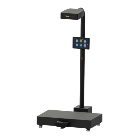
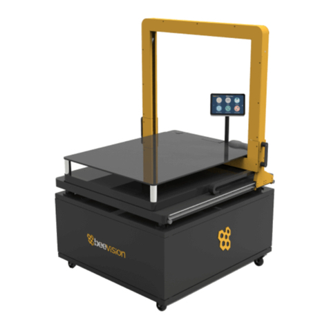
beevision BeeVision 272 User manual

BeeVision 272
Version 1.3.2
USER
MANUAL

1
CONTENTS
1. Preface ................................................................................... 2
2. Description of The Product and Intended Use ...................... 4
2.1 Important Information ........................................................ 4
3. General Information .............................................................. 5
3.1 Overall Dimensions .............................................................. 5
3.2 Main Parts ........................................................................... 5
4. Using the Device .................................................................... 8
4.1 Turning On/Off .................................................................... 8
4.2 Measurement Area .............................................................. 9
4.3 Volumizer .......................................................................... 10
4.4 Calibration ......................................................................... 16
4.5 Operation .......................................................................... 20

2
1. Preface
This document describes the usage of the BeeVision 272
dimensioning system. Permission must be obtained from 3DTİM
Elektronik A.Ş. (3DTIM) to copy, reprint and translate this document
in whole or in part. This manual may not be published, in whole or in
part, or used without authorization for competitive purposes. 3DTIM
reserves the right to make technical changes for improvement.
BeeVision 272 can only be used for dimensioning measurements
of opaque pallets and objects with a maximum size of 2400 x 2400 x
2400 mm (WxDxH). Any use other than this purpose is deemed illegal
and constitutes a misuse of the machine. If it is used in this way, all
responsibility will be on the user.
BeeVision 272 is under warranty for 1 year. Malfunctions
resulting from user error or the use of the device not in accordance
with the user manual are not covered by the warranty.

3
Figure 1.1
Figure 1.2

4
2. Description of The Product
and Intended Use
BeeVision 272 is an industrial product used for object
dimensioning. It is designed for measuring the dimensions of opaque
pallets and objects with a maximum size of 2400 x 2400 x 2400 mm
(WxDxH). The total weight of BeeVision 272 is 27 kg.
BeeVision 272 will not function correctly in direct
sunlight. It is designed for indoor usage.
2.1 Important Information
• The maximum object size is 2400 x 2400 x 2400 mm
(WxDxH).
• The minimum object size is 300 x 300 x 300 mm (WxDxH).
• The device may not measure accurately outside the 0-40°C
temperature range.
• The fans in the units turn on and off depending on the
ambient temperature.
• BeeVision 272 cannot measure transparent objects such as
glass, plastic, or nylon.
• A monitor should be connected to BeeVision 272 for
calibration and usage.

5
3. General Information
3.1 Overall Dimensions
The dimensions of the BeeVision 272 are 2740 x 375 x
405mm (WxDxH). The specified dimensions are shown in Figure 3.1
below (units are in mm).
Figure 3.1
3.2 Main Parts
Camera Unit: There are 2 camera units located at both ends of the
device. Cameras capture 2- and 3-dimensional images from both
corners.
Mounting Brackets: Brackets allow the user to mount the device on
walls or ceilings. The distance between the device and measurement
surface is important, please refer to the installation manual for the
correct installation.

6
Sigma Profiles: There are 2 sigma profiles on which Camera Units and
Processor are mounted on.
Processor: Processor collects data from Camera Units and runs the
measurement software.
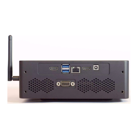
Wireless Antenna: Antenna is used for Wi-Fi connection.
Connectors:
1. POWER MAIN: This port is the main power port of the device.
2. ETHERNET: You can use this port to connect an ethernet
cable.
3. USB OUT: You can use this port to connect a USB cable.
4. USB DISP: USB port for touch screen operation of the
monitor.
5. HDMI DISP: Video output for the monitor.
6. POWER DISP: Power output for the Monitor.
7. USB BARCODE: USB connection for the handheld barcode
reader.
8. SERIAL: RS232 connection for the scale.
9. USB H1: Data port for the Camera Unit 1.
10. USB H2: Data input for the Camera Unit 2.
If you are going to add a monitor to your system, you
should use the HDMI Display port, and if the monitor
is touchscreen, you should use the USB Disp Port. If
you are going to use a 12V Monitor, don’t use the
Power Disp Port. You can supply power by simply
plugging it into any socket with the adapter.

7
The +12V input of the power_main and power_disp
connectors is the left pin when viewed from the
back of the processor head.
Figure 3.2
11. POWER H1: Power port for the Camera Unit 1.
12. POWER H2: Power port for the Camera Unit 2.
Figure 3.3

8
4. Using the Device
4.1 Turning On/Off
When the power cord is inserted into the power port and
given mains voltage, the system will be ready for use. The input
mains voltage BeeVision dimensioner must be at an interval between
100V-240V and 50Hz-60Hz.
To turn off the device, simply unplug the power cord.
The mouse cursor is by default hidden in Volumizer UI. If you
would like to connect a mouse and a keyboard, you can
enable/disable the mouse cursor with Ctrl+Shift+M combinations on
your keyboard.
Please refer to the Software Guide for more
details on how to integrate BeeVision into your
system.

9
4.2 Measurement Area
There are two Camera Units at both ends of the device. The
field of view of these cameras is shown in Figure 1.1. For the device
to measure an object, the object must be placed on a flat surface that
was used for calibration.
Figure 4.1
For maximum measurement accuracy, you must
mount the components in the positions shown in
the installation manual.

10
Make sure that the dimensions of objects are less
than 2400 x 2400 x 2400 (WxDxH) mm. Otherwise,
the object will not fit in the field of view.
4.3 Volumizer
Volumizer is the software installed in the BeeVision
dimensioners that enable users to control the device, perform
calibration and measurements. It has a graphical user interface (GUI)
that can be used when BeeVision is connected to a monitor.
Figure 4.2

11
It also has a web-based user interface (Web UI) that can be
accessed from a browser with the following address:
http://IP_address_of_device. The officially supported browser is
Google Chrome.
Figure 4.3
If you use a different browser than Google Chrome,
some functions may not work as expected.
Users can navigate to the pages from the main
menu as shown in Figure 4.2 and Figure 4.3.

12
Following pages are included in Volumizer GUI and Web UI:
Brings up dimensioning
submenu
Dimension
Measure
Trigger measurement and
display results
Perform calibration and view 3D,
2D, and model data
Calibration
Measurement
Settings
Change measurement settings
Measurement in
Groups
Perform measurements in
groups and save results to a
remote address as an XML file
per group

13
Source
Merge outputs of multiple
cameras
Brings up the barcode decoding
submenu (might be disabled
depending on the model)
Decode
Integration
Change result sharing options
Change Ethernet and Wi-Fi
settings
Network Settings
Change system settings such as
language, time, date, and device
operation mode
System Settings
Brings up the external devices
submenu
External Devices

14
Scale Settings
Change scale connection
settings
Scanner Settings
Change handheld and fixed-
mount barcode scanner
connection settings
Printer Settings
Change label printer settings
Conveyor Settings
Change conveyor and PLC
connection settings (might be
disabled based on the model)
Ip Cam Settings
Change IP camera settings
(might be disabled based on the
model)
Browse History
Browse previous measurement
results

15
View information about the
system such as model name,
certification status, SW
checksum, etc.
System Information
Restarts the device.
Reboot
View system log and parameter
changelog.
Logs
GUI Navigation Icons:
Opens up the previous upper menu page.
Opens up the main menu page.

16
4.4 Calibration
BeeVision 272 dimensioning system is not delivered as pre-
calibrated. The calibration process should be done after the device is
installed at its final location. For calibration, a checkerboard and a
cube with a size of 300 x 300 x 300 mm are provided.
The camera units’ outputs are first merged, then the system is
calibrated. Follow the instructions below to perform these steps.
Merging Cameras: In the main menu, navigate to the “Dimension”
submenu, and press the “Source” button. In this screen, you can see
the camera views. Place the calibration checkerboard in the center
of the red-colored bounding box shown in Error! Reference source
not found.. Then place the sheet metal parts around the
checkerboard to firmly fix the paper on the ground. At this stage, be
careful that the sheet metal parts do not come over the squares.
After that, click the Merge button. When the process is finished, shift
the calibration object to the new position as indicated on the screen
and put the sheet parts again, click the OK button. When operation
is completed, “Merging Status” will indicate “Done”.
Figure 4.4
Calibration: Go back to the upper menu and click the “Calibration”
button.

17
Step 1: Crudely select the measurement area using (+) and (-)
buttons. If there is a scale, you should select the scale and not include
the floor. Make sure the selected area is clearly smaller than the
measurement surface area (scale surface). Go to Step 2.
Figure 4.5
Step 2: Remove any objects from the calibration area defined in the
previous step and press the Calibrate button. Measurement surface
is detected and indicated in white color. Then, go to the next step.
Figure 4.6

18
Step 3: Define the measurement area finely using (+) and (-) buttons.
Make sure the measurement area exceeds the scale surface from all
dimensions and go to next step.
Figure 4.7

19
Step 4: Place the calibration cube of 300 x 300 x 300 mm dimensions
in the middle of the measurement area. Click the Refine Calibration
button. When the process is completed, press “Measure” button to
measure the cube and check the results to be within ±0.5cm
tolerance. If the height is not within tolerance, please go back to Step
2and refine the distance to the measurement surface manually and
come back to this step and re-measure. Do not forget to click on
“Save Calibration” button when done.
Figure 4.8
This manual suits for next models
1
Table of contents
Other beevision Measuring Instrument manuals
Popular Measuring Instrument manuals by other brands

Levenhuk
Levenhuk Wezzer BASE L30 user manual

Metek
Metek 920 Operator's Guide With Essential Health and Safety Requirements
Panametrics
Panametrics CGA 351 user manual

Haglof
Haglof Digitech user guide
horiba
horiba HU-200SS SS-90 instruction manual
Berkeley Varitronics Systems
Berkeley Varitronics Systems PTC-HOUND Quick start user guide
