beevision 270 User manual


2 BeeVision 270 User Manual v1.3.9
C Contents
1 Overview ......................................................................................................... 3
2 Installation ...................................................................................................... 3
3 Connection Ports ............................................................................................. 5
4 Turning ON/OFF .............................................................................................. 6
5 Field of View .................................................................................................... 7
Optical Center ....................................................................................................... 7
Field of View .......................................................................................................... 7
6 Communication Interfaces .............................................................................. 9
7 Volumizer ........................................................................................................ 9
8 Operation ...................................................................................................... 13
9 Technical Drawings ....................................................................................... 15

BeeVision 270 User Manual v1.3.9
3
1
1 Overview
This document provides a description of installation, calibration, and usage of
BeeVision
TM
270 dimensioner.
BeeVision dimensioners are equipped with Volumizer
TM
software that enables users
to easily self-calibrate the device, perform measurements and share results. Users can
use the BeeVision Dimensioners with Volumizer-GUI available on an attached monitor
or with Volumizer-WebUI from their browser on their PC, tablet or smart-phone.
With Volumizer-API, users can control their dimensioner remotely and integrate it
into their software infrastructure.
BeeVision dimensioners are designed as stand-alone devices. There is no need to have
a PC to get the results from BeeVision devices or install a separate software.
2
2 Installation
BeeVision 270 can be mounted over a stationary platform to measure static objects
as depicted in F
IGURE
1.
F
IGURE
1:
B
EE
V
ISION
S
TATIC
S
YSTEMS

4 BeeVision 270 User Manual v1.3.9
BeeVision 270 can be attached to any platform with 5mm screws depicted in FIGURE
2. BeeVision 270 is also delivered with a mounting-bracket that is screwed to the
device and can be used to easily mount the device to sigma-shaped profiles as shown
in FIGURE 3.
FIGURE 2: BEEVISION MOUNT BRACKET
FIGURE 3: BEEVISION 270 MOUNTED ON SIGMA PROFILES

BeeVision 270 User Manual v1.3.9
5
3 3 Connection Ports
F
IGURE
4 below shows the connection ports that are located on the backside of the
device.
F
IGURE
4:
B
ACK
S
IDE
O
F
B
EE
V
ISION
270
HDMI port: There are two HDMI ports to connect to an external monitor to view
Volumizer user interface (UI).
Even though it may work, it is not recommended to use a USB monitor
with the device.
Serial port (RS232): Typically used for establishing a connection with scales or
weighing instruments.
USB 3.0 port: There are two USB 3.0 ports. Zebra-brand barcode printers can be
also connected to ports. Handheld barcode scanners can be connected to USB
ports as well.
Ethernet port: To communicate with any computer or server system for the data
transfer.
Power port: To supply 12V to the device. Please use the adapter provided with
the BeeVision dimensioner.
Wireless antenna: Antenna performs data transfer by establishing wireless
communication with a wireless modem device/PC.

6
BeeVision 270 User Manual v1.3.9
Reset button: When pressed, the device is shut down gracefully. When pressed
for 3 seconds, device is forcefully shut down.
4
4 Turning ON/OFF
When the power cord is inserted into the power port and given mains voltage,
the device is automatically turned on and will be ready for use. The input mains
voltage for the power adapter provided with BeeVision dimensioners must be at
an interval between 100V-240V and 50Hz/60Hz.
To connect the BeeVision dimensioner to a computer or a local network for data
transfer, simply use an Ethernet cable. A detailed explanation of the connection
settings is provided in the Software Guide document.
In order to view the results of measurements and device settings on a monitor,
just connect one end of any standard HDMI male-to-male cable to the HDMI port
of the device and the other end to the monitor. If you use a touch-screen monitor,
connect the USB cable to one of the USB 3.0 ports on the device for enabling touch
operation. After connecting the cable for the first time, you may need to restart
the device depending on the driver of the touch-screen monitor. If you have
problems using the touch-screen, get in touch with the 3DTIM support team.
The mouse cursor is by default hidden in Volumizer UI. If you would like
to connect a mouse and a keyboard, you can enable/disable mouse
cursor with Ctrl+Shift+M combinations in your keyboard.
To turn off the device, simply unplug the power cord.
BeeVision starts in headless mode when no monitor is attached and the
device can only be controlled via Volumizer-WebUI or Volumizer API
web services. In order to bring up Volumizer GUI, connect a monitor and
reboot the device.

BeeVision 270 User Manual v1.3.9
7
5
5 Field of View
Optical Center
The optical center of the device is shown in F
IGURE
5
below. When mounting the
device, align it according to the optical center and center the projection of this
point on the measurement area.
F
IGURE
5:
O
PTICAL
C
ENTER OF
T
HE
B
EE
V
ISION
3DT270
Field of View
The field of view of BeeVision is 64x41 as illustrated in F
IGURE
6. There should
be at least 45 cm distance between the object and the device for proper
measurement operation.

8
BeeVision 270 User Manual v1.3.9
F
IGURE
6:
H
ORIZONTAL AND
V
ERTICAL
F
IELD OF
V
IEW
Measurement area of the BeeVision 270 dimensioner is set in the calibration
page. The measurement area should be in the field of view of the device. When
using a single device, some parts of irregular objects may remain out of sight of
the device as illustrated in F
IGURE
7. Only the surfaces that are visible to the device
are included in measurement calculations.
F
IGURE
7:
B
LIND
S
POT
I
LLUSTRATION

BeeVision 270 User Manual v1.3.9
9
6 6 Communication
Interfaces
Following communication interfaces are supported with BeeVision devices.
USB interface for connection of printer, barcode scanner or similar
Serial interface for connection of scale or data transfer to user computer
Ethernet interface for communicating over the internet or local network
to a central server of user
7 7 Volumizer
Volumizer is the software installed in the BeeVision dimensioners that enables users
to control the device, perform calibration and measurements. It has a graphical user
interface (GUI) that can be used when BeeVision is connected to a monitor. It also has
a web-based user interface (WebUI) that can be accessed from a browser with the
following address: http://IP_address_of_device .Google Chrome browser is officially
supported.
Users can navigate to pages from the main menu as shown in FIGURE 8 and FIGURE 9.
FIGURE 8: MAIN MENU OF VOLUMIZER GUI

10
BeeVision 270 User Manual v1.3.9
F
IGURE
9:
V
OLUMIZER
W
EB
UI
Following pages are included in Volumizer GUI and WebUI:
Brings up dimensioning submenu
Dimension
Measure
Trigger measurement and display
results
Calibration
Perform calibration and view 3D, 2D
and model data
Measurement
Settings
Change measurement settings

BeeVision 270 User Manual v1.3.9
11
Measurement
in Groups
Perform measurements in groups
and save results to a remote address
as an XML file per group
Source
Merge 3D data with a slave, remote
BeeVision device
Brings up barcode decoding submenu
(might be disabled depending on the
model)
Decode
Integration
Change result sharing options
Change Ethernet and Wi-Fi settings
Network Settings
Change system settings such as
language, time, date and device
operation mode
System Settings
Brings up external devices submenu
External Devices
Scale Settings
Change scale connection settings

12
BeeVision 270 User Manual v1.3.9
Scanner
Settings
Change handheld and fixed-mount
barcode scanner connection
settings
Printer
Settings
Change label printer settings
Conveyor
Settings
Change conveyor and PLC
connection settings (might be
disabled based on the model)
Ip Cam
Settings
Change IP camera settings (might be
disabled based on the model)
Browse History
Browse previous measurement results
View information about the system such
as model name, certification status, SW
checksum, etc.
System Information
Restarts the device
Reboot
View system log and parameter change
log
Logs

BeeVision 270 User Manual v1.3.9
13
GUI Navigation Icons:
Opens up the previous upper menu page
Opens up the main menu page
Functions of pages are described in details in the following sections.
8
8 Operation
Before starting measurements, the BeeVision dimensioners must be calibrated.
Calibration is done only once the sensor is mounted. If its height with respect to
the measurement surface is not changed, there is no need to recalibrate the
device. Measurement area is set during the calibration process. After the
calibration, the device may be sealed for certification purpose.
To perform a measurement, an object must be placed into the measurement area
and measurement should be triggered either automatically or manually
depending on the selected trigger mode. During measurement, there must be
only one object in the measurement area. Objects can be placed with any
orientation to any location in the defined measurement area. BeeVision
dimensioners cannot measure transparent objects such as glass.
If the objects dimensions are outside of the limits of devices range, then an error
message may be displayed if corresponding check is activated in Measurement
Settings.
There are several trigger modes in BeeVision dimensioners:
Manual Triggering: Manual operation mode. The user needs to press Measure
button in GUI or WebUI to perform measurement.
Barcode Scanner Triggering: The user needs to scan a barcode with an attached
barcode scanner to start a measurement. Measurement is triggered after the scan
event. In addition to the dimensioning results, barcode is also shown.

14 BeeVision 270 User Manual v1.3.9
Automatic Triggering: Automatic operation mode. Whenever a package is placed
into the measurement area, its dimensions are measured and shown.
Manual & Bar. Scanner Triggering: Manual and Barcode Scanner triggering
methods can be used at the same time.
Scale Triggering: When a package is placed into the measurement area,
measurement is automatically triggered after a certain time of delay. Scale should
transmit a value larger than 0 to start the triggering.
Trigger settings can be changed in Measurement Settings page of GUI or WebUI.
If scale connection is enabled in Scale Settings page, the weight result is also
indicated in the Measure page.
Calibration
To calibrate the BeeVision dimensioner, navigate to the Calibration page of UI or
WebUI and follow the steps explained below. You have to do the calibration just once
after you mount the device.
Step 1: Crudely select the measurement area using (+) and (-) buttons. If there is a
scale, you should select the scale and not include the floor. Go to the next step.
Step 2: Remove any objects from the calibration area defined in the previous step
and press the Calibrate button. Measurement surface is detected and indicated in
white color. Then, go to the next step.
Step 3: Define the measurement area finely using (+) and (-) buttons. The
measurement area can be larger than the scale. Go to step-4.
Step 4: Make test measurements. If the height is a little off, go back to Step-2 and
manually adjust the ground height for your convenience and retry measurement in
Step-4. Finally, save the calibration. If not saved, calibration results are reset after a
reboot.
After the calibration, you can go to the Measure page to start measuring.
For further details, please refer to the Software Guide documentation.
BeeVision 270 User Manual v1.3.9
15
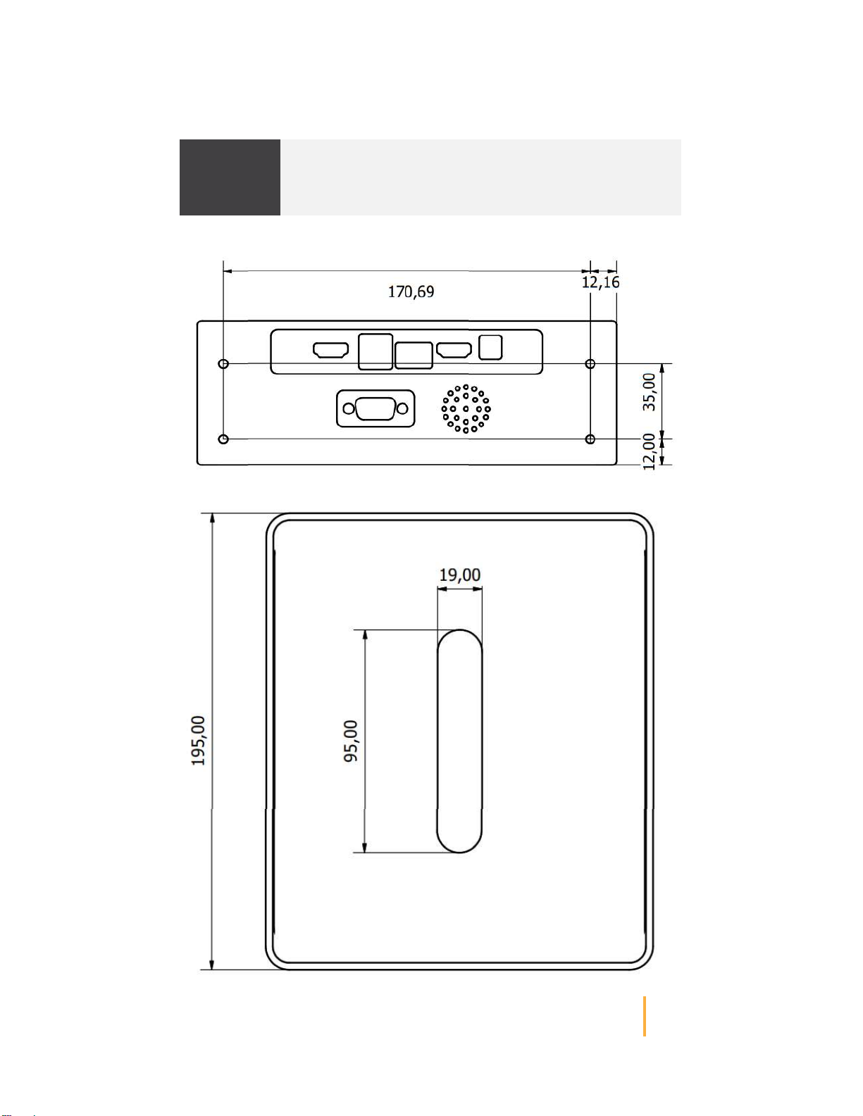
9 9 Technical Drawings

16
BeeVision 270 User Manual v1.3.9

BeeVision 270 User Manual v1.3.9
17
Notes
Table of contents
Other beevision Measuring Instrument manuals


