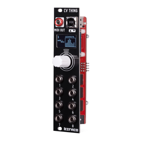
Befaco VCMC User manual

VCMC v1.1 - ASSEMBLY GUIDE Rev Apr 2021
THANKS FOR CHOOSING ONE OF OUR KITS!
This assemb y guide is a bit different from the other Befaco ones. We wi be assemb ing sections, and testing them one
by one, so we wi not keep bui ding unti we make sure it is working nice y.
This wi make our bui d a bit s ower and carefu , as this is quite a tricky build.
Some steps are not obvious, so even if you're an experienced DIYer, p ease take the time to read the steps thorough y
before starting.
If this is your first project, p ease read this artic e before you start assemb ing the kit:
www.befaco.org/howto/
VC C can be assembled as an Standalone unit. During the build we will point out the components you might
change. Check page 2 for details on this odification from Eurorack version.
OPEN BAG A
RESISTORS
Qty Va ue Code Name on PCB
14 100k Brown, b ack, b ack, orange, brown R6, R7, R11, R13, R14, R15, R16, R17, R18, R19, R20,
R21, R26, R29
11 1k Brown, b ack, b ack, brown, brown R12, R25, R27, R30, R31, R32, R33, R34, R35, R36,
R37
4 10k Brown, b ack, b ack, red, brown R1, R2, R9, R10
5 33k Orange, orange, b ack, red, brown R5, R22, R23, R24, R28
2 56 ohm Green, b ue, b ack, go d, brown R4, R8
1 2k2 Red, Red, b ack, brown, brown R3
DIODES
So der the diodes observing their polarity. The b ack or white ine on the diode must match with the white ine on
the diode symbo on the PCB si kscreen.
Qty Va ue Name on PCB
2 1N5817 D1, D2
6 BAT85 D3, D4, D5, D6, D7, D8
FERRITES
So der the two ferrite beads by using a recyc ed diode eg passed through each ferrite and proceed as if it were a
resistor. Ferrite beads don't have po arity.
Qty Name on PCB+
2 F1, F2
1

VCMC v1.1 - ASSEMBLY GUIDE Rev Apr 2021
IC SOCKETS
First we will place the sockets (taking care to orientate them proper y – the notch on one end of the socket shou d match the
si kscreen) and so der them into their correct positions. Get them from ICs bag.
Qty Va ue Name on PCB
2 DIL8 IC3, IC6
2 DIL16 IC4, IC5
OPEN BAG B
CAPACITORS
Identifying capacitors can be quite tricky. Codes stated are indicative, p ease take a ook at this guide for he p identifying
capacitors: http://www.wikihow.com/Read-a-Capacitor
Qty Va ue Code Name on PCB
15 100n 104 C3, C4, C5, C6, C7, C8, C9, C10, C12, C16, C18, C19, C20, C22, C23
5 10uF (POLARIZED!)10uF C1, C2, C13, C14, C15
2 1nF 102 C11, C21
1 22p 220 C17
At this point you can choose to finish your bui d for a VCMC powered by Eurorack, or if you want your modu e to be powered via the
USB port and make it standa one. Check every step for your re evant option, this is a critical part.
REGULATORS
Make sure it is positioned correct y with reference to the si kscreen out ine on the PCB
Qty Code Name on PCB
2 78L05 REG5A, REG5B *
1 78L33 REG1
1 LM4040 REG-10
* Do not p ace these regu ators if you are assemb ing VCMC as standa one unit.
POWER SECTION
So der the power connector, ensuring the position is correct: it must be p aced over the si kscreen, check that the notch on the
connector is p aced where the itt e rectang e is in the si kscreen.
Do not place Power connector if you are assembling VC C as standalone. For Eurorack version, ignore next steps.
For standa one version, p ace DC/DC 0512D instead. Its ocated over Power connector, abe ed IC1. P ace it in components side, as
the rest of the components.
P ace resettab e fuse in PTC and so der it.
Bridge JP2 with a b ob of so der.
The rest of the components in this bag will be mounted later in the process.
2

VCMC v1.1 - ASSEMBLY GUIDE Rev Apr 2021
TROUBLESHOOTING
At this point we wi perform a smoke test and check that power arrives to every re evant spot in the board.
This is very important, as testing a this once mechanica components are so dered wi be hard.
Connect the modu e to a power supp y and fo ow next page diagram to measure ALL marked vo tages.
If YOU ARE BUILDING STANDALONE VERSION, SOLDER USB CONNECTOR.
If your power supp y behaves funny or one of the regu ators get hot, unp ug the modu e immediate y. Possib e errors:
- One of the regu ators is reversed
- Reversed Diode.
- Reversed e ectro ytic capacitor.
- Maybe you have a bridge somewhere.
Use one of the marked GND spots and measure one by one the vo tages
If a vo tages are good (keep in mind they might change a bit due to to erances and your power supp y) proceed with the rest of the
bui d.
If you are facing issues, p ease fo ow our basic troub eshooting guide:
https://www.befaco.org/en/trubleshooting-questions/
3

VCMC v1.1 - ASSEMBLY GUIDE Rev Apr 2021
OPEN TEENSY BAG
PREPARING TEENSY
This part on the bui d is critica . We wi be so dering pins to our Teensy board, being
some of them SMD and EXTREMELY de icate. So p ease fo ow instructions and be extra-
carefu .
Scan this QR to check a video on our Youtube channe so dering the pins.
We wi prepare fema e pin headers that wi be so dered to the board, and ma e pin
headers that wi be so dered in Teensy board.
We wi try first to p ace them a , make sure they fit stress-free and then so der.
First of a we wi so der SMD pin headers to backside of Teensy board. Make sure that
you work on a c ear area. Try to fix Teensy board on a way that it wi not move and make work smoother. For
examp e, you can use ICs foam to stick it and make it stab e.
Cut the SMD connector so it is same size as the pads In the bottom of the board (2x7). Proceed to so der it making
sure they are centered in the pads and straight.
WARNING:
Pads in Teensy board are very de icate, treat them gent y, if so dering is
becoming hard, et it rest and try ater.
P ace ma e pin headers at Teensy ho es, but do not so der them. We wi be p acing them on the board first to make
sure it fits proper y. But on y after next step.
Now we wi proceed to p ace fema e pin headers in the pcb:
FE ALE PIN HEADERS
P ace a pins on the PCB to fit Teensy size, at components side, but do not solder them.
Qty Size P ace on PCB
2 1X14 Long sides
1 1X5 Short sides
1 2X7 Centra position
POGO PINS
P ace the pins on the PCB at components side (JP3) but do not solder them.
Qty Size P ace on PCB
2 1 Matching the Teensy SMD pads
P ace Teensy board on the fema e pins. Do this gently and make sure a pins are firm y connected and flat against the
board. Once a pins are in p ace, proceed to solder them all.
RE INDER: Be sure that the Pogo Pins are matching the Teensy pads before solder it.
4

VCMC v1.1 - ASSEMBLY GUIDE Rev Apr 2021
Now we wi mount the spacers and the OLED Screen which are ocated on the mechanica side of the PCB.
SPACERS
Secure the 7 mm. spacers onto the PCB in the upper side of the board, to fit the OLED screen. P ace them at
mechanica components side.
OLED SCREEN
Cut the 14p socket in ha f. Then p ace one of the ha ves In the 7 ho es for the OLED. Making sure it is not getting out
of the board. But do not solder it.
Cut OLED pins ~2mm so it wi be flat and para e to the PCB once attached to the socket. Then we wi p ace the OLED
to this socket, screw it to the spacers and proceed to solder the socket.
TROUBLESHOOTING
P ug the modu e and make sure that the screen is showing Befaco sp ash screen, then modu e main screen appears.
The bars wi be a bit crazy, it is norma ! If screen does not ight up, then something is fishy with your so dering either
in the Teensy or the OLED.
If it lights up, remove Teensy and OLED gently and continue with the build.
TRANSISTORS
Make sure it is positioned correct y with reference to the si kscreen out ine on the PCB
Qty Code Name on PCB
8 2n3904 T1, T2, T3, T4, T5, T6, T7, T8
ALE PIN HEADERS
P ace the 2x4 pin headers on EXP fo owing the si kscreen.
ICs
P ace ICs in their sockets. Take care of po arity, notch or dot mark orientation.
Qty Va ue Name on PCB
2 DG408 IC4, IC5
2 TL072 IC3, IC6
5

VCMC v1.1 - ASSEMBLY GUIDE Rev Apr 2021
Now we wi proceed to mount the jacks, MIDI connector, button and encoder. This part of the assemb y is CRITICAL.
P ease take your time and read the fo owing instructions carefu y.
These components must NOT be so dered unti they are p aced on the PCB and fu y attached to the front pane .
After so der every component of this bag, be sure that the egs are cut short enough in order to not touch the
mechanica components that we wi p ace and so der now.
OPEN ECHANICAL CO PONENTS BAG
SPACERS
Secure the 11 mm. spacers onto the PCB. These are the ones that go c ose to the buttons, p ace them facing
mechanical components as they wi be screwed to the pane ater on.
USB CONNECTOR
P ace USB connector but don't solder it yet.
INIJACK
P ace the mini-jacks on the PCB ensuring they are on the side with the si kscreen but don't solder them.
At this point we wi p ace and screw the OLED in p ace. So we can test the modu e a bit further.
Place front panel and screw the nuts (one in each corner shou d be enough). Screw a so the two spacers using two
M2 screws.
Solder inijacks and USB connector.
TROUBLESHOOTING
At this point we are ready to test CV and Gate inputs on the modu e. Put Teensy back in p ace gent y, then power the
modu e on .
P ug some CV sources to the inputs. You shou d see re evant co umns moving with the CV. Warning: Fader co umns
wi be moving crazy, pay attention to CV ones on y.
Connect the modu e to your computer via USB. It shou d be automatica y recognized and VCMC Midi contro er added
to your system. As a doub e check, you can see if MIDI messages are arriving.
If everything is fine, remove the panel and keep with the assemb y.
FADERS
Before p acing the faders make sure your so dering is tidy and regu ar.
P ace the faders on the PCB where the si kscreen indicates, make sure they are flat and proceed to so der the three
pins. Do not solder location lugs yet, wait ti the end of the bui d when everything is working fine.
TIP: Make sure no egs are bent and a are passing thru their ho es. A mistake here wi cause extreme suffering
ater.
If you power the modu e back in you shou d be ab e to check that fader co umns move according y.
ENCODER
P ace the encoder on the PCB where the si kscreen indicates. Leave the hex nut and two washers under the board but
don't solder it yet.
BUTTONS
P ace the push buttons on the PCB where the si kscreen indicates, taking care of the orientation. F at side must match
the si kscreen, don't solder them yet.
TIP: Make sure a egs passed thru ho es, fixing this ater is rather painfu .
6

VCMC v1.1 - ASSEMBLY GUIDE Rev Apr 2021
FRONT PANEL
P ace the plastic window into front pane OLED ho e, from the back side of the pane . Use some hot g ue, tape or any
method of your choice. Remember to remove the protection p astic from it.
Attach the front panel adjusting the parts one by one if necessary unti they fit. You can use some masking tape to
ho d the buttons in p ace before so dering.
To finish:
- Secure the parts to the pane in this order: A) ini-jacks B) Screws for the spacers C) Encoder
- Ensuring a of the above parts are flush with the pane then you can fina y solder the encoder.
- Next, we wi be so dering the push buttons. Press them to make sure they are flat, if you are not using
masking tape. Then so der them.
- So der the faders three contact pins, making sure they are straight and para e to the board. Do not so der
the four ocating pads. Wait unti the modu e is working and fu y tested.
FINAL TROUBLESHOOTING
Now is the time to p ug your modu e to check that everything is working as expected.
Modu e shou d power on and screen shou d show the booting sequence. If it does not boot, and/or you notice some
weird behavior or heating, disconnect the modu e and perform further troub eshooting. Keep in mind when was the
ast successfu test, so check what you did from there.
If modu e is booting, move faders and p ug some CV sources to the inputs to check if you can see feedback in the
screen. A so, pressing buttons shou d make the Leds b ink.
BEWARE OF TEENSY BUTTON: while testing, if button is pressed module will reboot!!
At this point taking a ook to our User manua might he p to understand if everything is fine.
After the basic testings are successfu , you can proceed to so der ocation egs of the faders.
IDI CONNECTOR
P ace the MIDI connector thru the ho e. P acing the nut just before connecting it to the board.
Fasten the nut so the connector is straight and flush against the PCB. Then so der PINS 4 and 5 (The two at the
sides of centra one).
So dering this at the very end is CRITICAL, as pane is rea y hard to remove once this connector is so dered.
Make sure everything works fine before doing so.
7

VCMC v1.1 - ASSEMBLY GUIDE Rev Apr 2021
CALIBRATION
We wi perform now a factory ca ibration. This procedure need to be done with a very precise vo tage source. We
suggest to measure with a three digits mutimeter.
In order to get into ca ibration mode, press the encoder for more than three seconds,this wi get you into genera
settings menu.
Scro to credits, when sp ash screen appears, keep encoder pressed in order to make G oba ca ibration option
avai ab e.
When sp ash screen disappears, scro down to access g oba ca .
- Calibrating Faders.
Move a faders to maximum position unti a va ues stabi ize. Then move a of them to zero. Press end to store the
va ues
- Calibrating CVs.
We wi be entering to a two points ca ibration screen. You wi be prompted to send 2v and 8 vo ts, so they wi be
stored and correcting any eventua offset and non inearity in your CV source.
Make sure your CV source is precise enough!
- Calibrating Aux.
We wi be entering to a two points ca ibration screen. You wi be prompted to send 2v and 8 vo ts, so they wi be
stored and correcting any eventua offset and non inearity in your CV source.
Make sure your CV source is precise enough!
ENJOY YOUR NEW BEFACO ODULE!
8

VCMC v1.1 - ASSEMBLY GUIDE Rev Apr 2021
9

VCMC v1.1 - ASSEMBLY GUIDE Rev Apr 2021
10
Other manuals for VCMC
4
Other Befaco Controllers manuals
Popular Controllers manuals by other brands

watt box
watt box WB-150-IPW-1B-2 quick start guide

Signature Control Systems
Signature Control Systems 810 Series Installation and programming guide

Welbilt
Welbilt Kolpak ArcticFox Deluxe Display Installation, operation and maintenance manual

Delta
Delta DVP-ES2 instruction sheet

EP Solar
EP Solar EPIP20-LT Series instruction manual

Wyrestorm
Wyrestorm NHD-000-CTL installation guide