Befaco Crush Delay User manual

C R U S H D E L A Y
U S E R M A U A L

C R U S H D E L A Y P O W E R & I T R O
P O W E R I G
T H E M O D U L E
U S E R M A U A L
T H A K S F O R P U R C H A S I G A M O D U L E F R O M B E FA C O !
B E F O R E Y O U P L U G T H I S M O D U L E I . . .
1.
Disconnect our cabinet from the mains.
2.
Triple check the power cord polarit .
The coloured line on the cable
(pin number one) is the -12V rail.
3. If you plug the module backwards you might burn it out and
unfortunately this is not covered by the warranty.
4. If you have any questions about this product please send them to:
befacosynth@gmail.com
I T R O D U C T I O W H A T I S C R U S H D E L A Y ?
Crush Delay is an special Echo-Delay unit based on the PT2399 IC, which although able to offer 400ms of
clean delay, having a special talent for generate noisy textures. The module bases its operation on control the
PT2399 chip with circuit bending techniques, converting the unit in an advance VC digital noise generator.
This third version comes with some interesting new features like redesigned VCAs circuits, more clean range
and less depth.
M O D U L E
R E F E R E C E PA E L O V E R V I E W
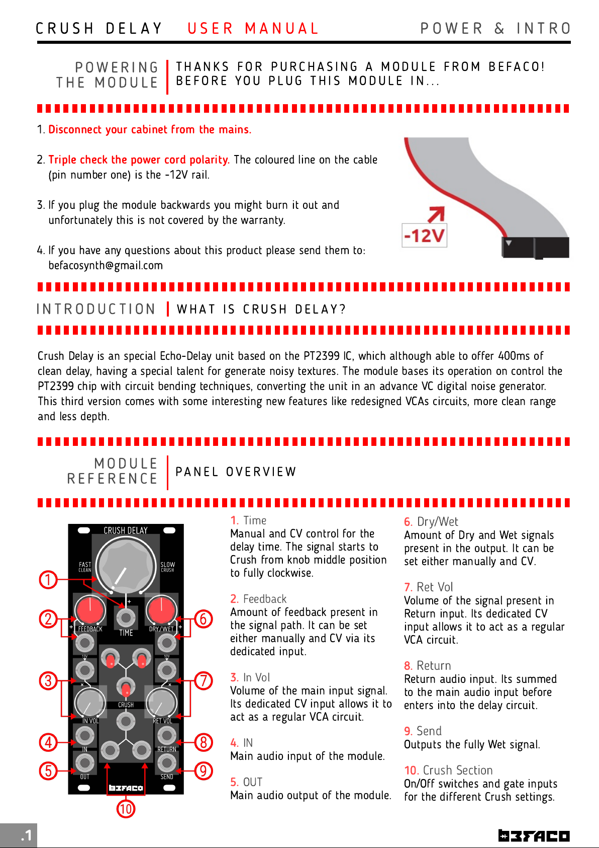
1.
Time
Manual and CV control for the
delay time. The signal starts to
Crush from knob middle position
to fully clockwise.
2.
Feedback
Amount of feedback present in
the signal path. It can be set
either manually and CV via its
dedicated input.
3.
In Vol
Volume of the main input signal.
Its dedicated CV input allows it to
act as a regular VCA circuit.
4.
IN
Main audio input of the module.
5.
OUT
Main audio output of the module.
.1
6.
Dry/Wet
Amount of Dry and Wet signals
present in the output. It can be
set either manually and CV.
7.
Ret Vol
Volume of the signal present in
Return input. Its dedicated CV
input allows it to act as a regular
VCA circuit.
8.
Return
Return audio input. Its summed
to the main audio input before
enters into the delay circuit.
9.
Send
Outputs the fully Wet signal.
10.
Crush Section
On/Off switches and gate inputs
for the different Crush settings.

C R U S H D E L A Y R E F E R E C E
F U C T I O A L
B L O C K S
U S E R M A U A L
I P U T S
.2
M O D U L E
R E F E R E C E B L O C K D I A G R A M
SIG AL PATH
With a quick look to the block
diagram, we can easily understand
Crus Delay
signal flow.
The module has two inputs (
IN
and Return
) that go to the
Delay
circuit throught a dedicated VCA
for each one. The main difference
between both inputs is that the
signal feeded into
IN
is going to
the
Dry/Wet
circuit too, not only to
the Delay, allowing you to control
balance between the original and
the processed signal, present at the
main output (
OUT
).
The signal is processed by the
Delay
circuit, which is affected by
the
Crus
section. It degrades the
signal at slow rates in different ways, depending of the position of the three
Crus
switches or by the
presence of gate signals at the
Crus
inputs.
After being processed, the signal is routed to three differnet paths. The first one goes into
Dry/Wet
, where it's
mixed with the original input signal (
IN
) before going to the main output (
OUT
). The second one is returned to
the
Delay
circuit through another VCA (
Feedback
), controlling the amount of repetitions of the wet signal.
Finally the last one goes directly to the
Send
output.
I
Is the main input circuit of the module. The signal goes through a
dedicated VCA to the Delay and Dry/Wet circuits. The
IN VOL
pot
controls the volume of the signal when nothing is patched at its
CV
Input
. This CV Input is normalled to 1 0V, so with a signal present on it,
the
IN VOL pot will act as attenuator of t at CV signal.
RETU R
Working as second input section of the module, Return has the same
internal structure of the I circuit, the main difference between both is
that the signal present at Return input is not routed to the Dry/Wet
circuit,
only to Delay
. As well as I , Return has a dedicated VCA with
manual (
RET VOL
) and CV controls. The CV input of the VCA is also
normalled to 1 0V, so
RET VOL will act as attenuator of any CV
signal present
on it.

The
Crus
section is the most unique feature of Crush
Delay. It is formed by three Crush modifiers designed with
circuit bending techniques.
T ose modifiers affects t e
Delay circuit c anging its be aviour
and allowing you
to create different tonalities and noise sounds.
Each modifier can be activated manually via its dedicated
switch or by feeding a Gate signal on its Gate Input.
Gate
Input t resold: 3V.
Combining the modifiers you will have a access to a vast
palette of noises and textures that can be used in many
different ways. From ambient/drone patches to even
percussion sounds.
C R U S H D E L A Y R E F E R E C E
U S E R M A U A L
.3
F U C T I O A L
B L O C K S D E L A Y C I R C U I T
TI M E
Time is the main parameter on the Delay circuit. It sets how much time
the incoming signal will be delayed. The unit is modified by special
circuit bending techniques (
Crus
section) that distorts the signal at
slowest rates. The module is able to offer 400ms of Clean delay from
counter-clockwise position of the
Time
pot till the middle aprox, and
starts to crush from middle to fully-clockwise position.
The dedicated CV input sums the incoming voltage to the current
position of the pot, allowing you to control the amount of crush present
in the wet signal for example. This input expects a voltage range of +/-
1 0V.
FEEDBACK
After being processed by the Delay circuit, the signal pass thru another
VCA circuit and returns its way back to the Delay. This process called
Feedback is the responsable of create the repetitions that essentially
conforms the effect that we mean by Delay.
Using the
Feedback pot and its dedicated CV input we can control
t e amount of t ose repetitions
. As well as in Time section, the CV
input sums the incoming voltage to Feedback pot position. +/-1 0V
expected.
DRY/WET
This circuit controls the balance between the original and the processed
signal present at the main output (
OUT
). The dedicated CV input sums
the incoming voltage to the current position of the
Dry/Wet
pot. +/-1 0V
expected.
F U C T I O A L
B L O C K S C R U S H S E C T I O

C R U S H D E L A Y R E F E R E C E
U S E R M A U A L
.4
M I S C E L A E A S P E C S & C R E D I T S
* Size
: 11HP
* Dept
: 30mm
* +1 2v:
1 30mA
* -1 2v:
30mA
* Design
: Pascual Rocher
* Special t anks to
all Befaco Team for their
unvaluable help during the development process.
Table of contents
Other Befaco Measuring Instrument manuals