INSTALLATION
Airflow is vital to the performance of this product.
Install with AT LEAST 12" (30cm / 300mm) clear space on both ends and do not block ventilation holes.
1. Extend un-switched 24-hour AC supply of rated voltage to the unit, installed in accordance with all applicable codes
and standards. This circuit should NOT be energized/live at the time.
2. Unscrew the cover screws on the sides of the unit. Lift and remove the front cover .
3. Knockouts are stamped into the back and side of the cabinet. Knock out the appropriate hole(s) and bring wires
through them into the cabinet.
4. Mount the unit securely into place. This unit is FLOOR MOUNT ONLY!
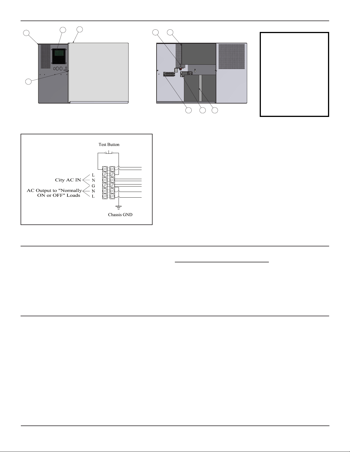
5. Make proper wiring connections between the AC supply and terminal blocks within the unit (see AC Wiring
diagram, page 2).
6. Make proper load connection to the terminal block (see AC wiring diagram above).
7. Batteries are shipped separately. Install batteries into the cabinet and complete the appropriate connection:
Red wire to positive battery terminal (+) and Black wire to negative battery terminal (-).
8. Route wires and secure in place.
9. Select Load Operation Mode (N-ON / N-OFF) from the internal toggle switch .
10. Replace cover and secure with cover screws .
11. Turn on AC line voltage supply.
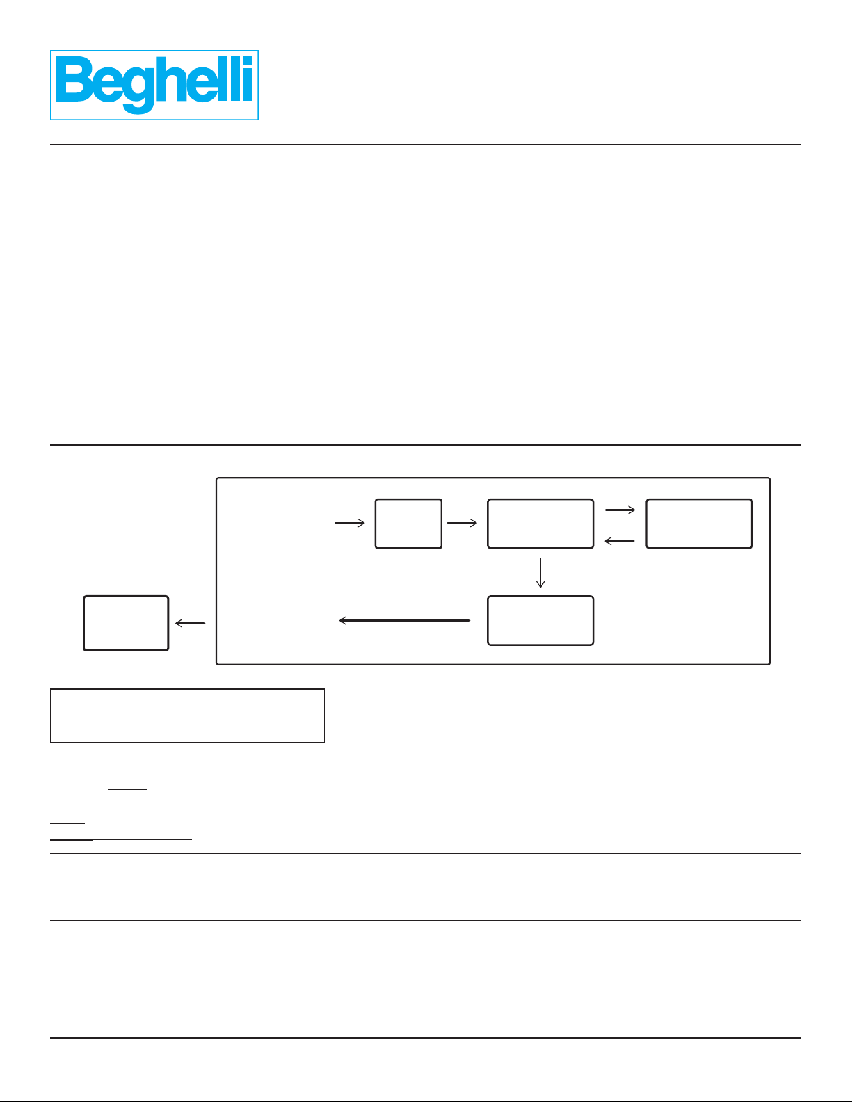
UNIT RESET
1. Disconnect AC input, disconnect batteries from inverter, disconnect load.
2. Wait 10 seconds; measure battery voltage during wait period to verify condition.
3. Reconnect batteries, and then reconnect AC input.
4. If unit turns ON with no error notifications, turn OFF unit with power button and disconnect AC before reconnecting
lighting load.
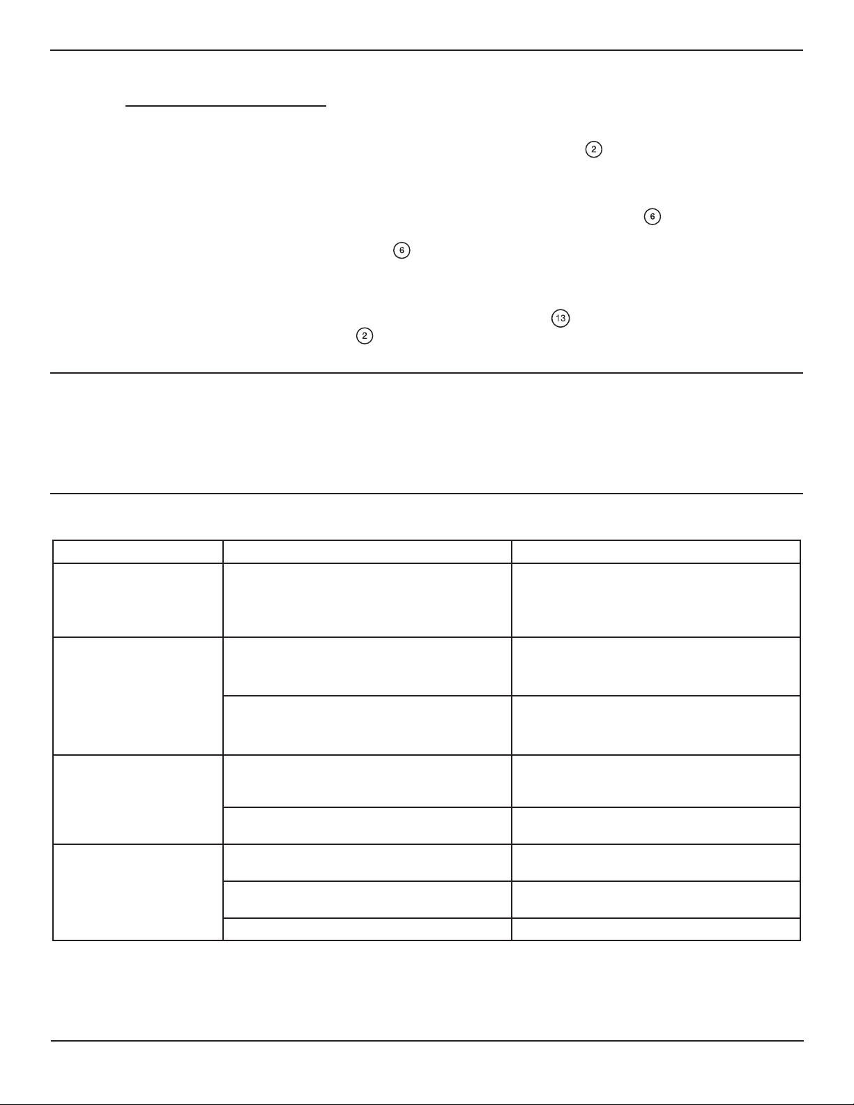
TROUBLESHOOTING
Problems Reasons Solutions
No AC output voltage
during emergency
Surge (or inrush) of lighting load exceeds
inverter’s maximum, causing unit shutdown
• Reduce number of connected lighting
fixtures, or replace with lower-surge
fixtures
• Reset unit
No AC output voltage,
with AC input present
(N-ON mode only)
Lighting load exceeds inverter’s maximum
capacity, causing unit shutdown
• Reduce number of connected lighting
fixtures
• Reset unit
Short-circuit, causing AC output circuit
breaker to trip
• Locate and clear short-circuit
• Reset circuit breaker located on inverter
box inside the unit enclosure
Unit does not turn ON,
with AC input present
Battery voltage is lower than acceptable
threshold
• Disconnect battery and recharge by
separate means; battery may need
replacement
Battery is not connected to inverter box • Connect 12V battery terminals to
inverter
Unit does not last up to
required emergency
duration
Battery is not fully charged • Allow battery recharge for up to 24
hours
Lighting load exceeds unit rating • Reduce number of connected lighting
fixtures to below unit power rating
Batteries are defective, or aging • Replace batteries
926000090
Beluce Canada Inc., 3900 14th Avenue, Markham, ON L3R 4R3 Tel: (905) 948-9500 Fax: (905) 948-8673
06/09/2019