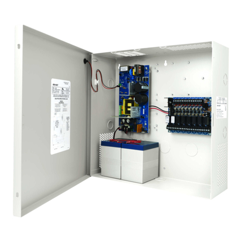
Assa Abloy ADAMS RITE PS-SE Operating instructions

1 80-0180-339, Rev 2
PS-SE Power Supply
Owner’s Manual
and
Installation Instructions

2 80-0180-339, Rev 2

3 80-0180-339, Rev 2
Table of Contents
Theory of Operation ..................................................................................4
Configuring the PS-SE..............................................................................4
Ensure the Primary Voltage ..................................................................4
Set the Operation Mode .......................................................................5
Set the Hold Open Time........................................................................5
Connect the Fire Alarm Control ............................................................7
Wire the Input Control Switches...........................................................7
Wire the PS-SE to the Exit Devices........................................................8
Install the Battery Backup System (BBK-SE)..........................................8
Wire the Automatic Door Interface (Optional)...................................10
Wire the Primary Power Connection ..................................................10
Descriptions, Part Numbers, and Measurements...................................11
Descriptions and Part Numbers ..........................................................11
PS-SE Value Readings ..........................................................................11
LED Configuration ...............................................................................11
Frequently Asked Questions...................................................................11
Troubleshooting ......................................................................................12
Approved Replacement Fuses................................................................14
Connector Signal Descriptions................................................................15
SE Exit Device Configuration..................................................................15
4 80-0180-339, Rev 2
Theory of Operation
The Adams Rite Power Supply (PS-SE) provides power and control for
up to two exit devices. Each exit device is controlled by a timer that is
initiated by a switch closure. The timer is user configured and holds the
exit device(s) in the unlatched position for 2–60 seconds. At the end of
the selected time, the exit device(s) will re-latch. If the switch controlling
the exit device is held closed longer than the selected time, the exit
device remains unlatched until the controlling switch is released.
An optional mode is available allowing both retraction timers to activate
in response to closure of either switch.
The PS-SE is listed as an Exit Device, Access Control System unit to
UL305 and UL1012 requirements for power supplies and CAN / CSA -
C22.2.
Exit devices under the system control remain latched during a complete
power failure but always allow free mechanical egress.
Configuring the PS-SE
CAUTION
Damage to the PS-SE or to exit devices may occur if connections
are not made in accordance with the following procedure, or if
connections are bypassed or omitted.
Ensure the Primary Voltage
NOTE: The PS-SE is rated
for 120 VAC only. Switch 2
(SW2) is factory preset for 120
VAC operation.
1. ENSURE the PS-SE is set
to 120 VAC.
Figure 1. Primary Voltage

5 80-0180-339, Rev 2
Set the Operation Mode
NOTE 1: The PS-SE has two operation modes, Single Input (Sequential
Operation) and Dual Input (Independent Operation), as
follows:
Single Input (Sequential Operation)
Application: Control one opening
Operation: Either input retracts Exit Device #1,
immediately followed by Exit
Device #2.
Dual Input (Independent Operation)
Application: Controls two separate openings
Operation: Input IN1 retracts Exit Device #1,
Input IN2 retracts Exit Device #2.
NOTE 2: The PS-SE is factory preset for Single Input (Sequential
Operation).
1. SET the desired operation mode using SW1 dip switch 1 on the
PS-SE.
Figure 2. Operation Mode
Set the Hold Open Time
NOTE: The PS-SE has two hold open timers.
1. PERFORM the following to set the hold open times.
a. SET the hold open time for Exit Device #1 using SW1 dip
switches 3, 4, and 5 (see Table 1, “Solenoid Hold Time Settings
for Exit Device #1,” for settings and hold times, and Figure 3,
“SW1 Dip Switch Settings,” for hold time settings example).

6 80-0180-339, Rev 2
Table 1. Solenoid Hold Time Settings for Exit Device #1
Dip
Switch
2
sec
5
sec
10
sec
15
sec
20
sec
30
sec
45
sec
60
sec
3
OFF
ON
OFF
ON
OFF
ON
OFF
ON
4
OFF
OFF
ON
ON
OFF
OFF
ON
ON
5
OFF
OFF
OFF
OFF
ON
ON
ON
ON
b. SET the hold open time for Exit Device #2 using SW1 dip
switches 6, 7, and 8 (see Table 2, “Solenoid Hold Time Settings
for Exit Device #2,” for settings and hold times, and Figure 3 for
hold time settings example).
Table 2. Solenoid Hold Time Settings for Exit Device #2
Dip
Switch
2
sec
5
sec
10
sec
15
sec
20
sec
30
sec
45
sec
60
sec
6
OFF
ON
OFF
ON
OFF
ON
OFF
ON
7
OFF
OFF
ON
ON
OFF
OFF
ON
ON
8
OFF
OFF
OFF
OFF
ON
ON
ON
ON
Figure 3. SW1 Dip Switch Settings

7 80-0180-339, Rev 2
Connect the Fire Alarm Control
NOTE 1: Use of the PS-SE power supply with fire doors requires the
system be under the control of an automatic fire alarm control
system.
NOTE 2: The PS-SE is factory preset to be used without a fire alarm
interface.
1. ENSURE the installed jumper is in place between Positions 9 and
10 (Fire) of the J3 terminal block to use the PS-SE without a fire
alarm interface.
2. PERFORM the following to use the PS-SE with a fire alarm interface.
a. REMOVE the jumper wire installed between Positions 9 and
10 (Fire) of the J3 terminal block.
NOTE 1: Closed relay contacts indicate No Alarm Condition
NOTE 2: When a fire alarm occurs, the controlled exit devices will
immediately latch secure. Exit devices remain latched
during a fire alarm, but always allow free mechanical
egress.
NOTE 3: The maximum current through the fire alarm contacts is
120 mA at 24 VDC.
b. CONNECT the fire alarm normally closed relay contacts to
Positions 9 and 10 (Fire) of the J3 terminal block.
Wire the Input Control Switches
1. WIRE the normally open activation switch (dry contacts) for Exit
Device #1 to the IN1 terminals (J3-3 and J3-4) on the J3 terminal
block.
NOTE: The exit device is rated for continuous duty.
2. WIRE the normally open activation switch (dry contacts) for Exit
Device #2 to the IN2 terminals (J3-1 and J3-2) on the J3 terminal
block.

8 80-0180-339, Rev 2
Wire the PS-SE to the Exit Devices
NOTE: The maximum length listed with each wire gauge must never
be exceeded.
1. WIRE the PS-SE to the exit devices using the information in Table 3,
“Wire Gauge and Lengths.”
Table 3. Wire Gauge and Lengths
Maximum Cable Length
Wire Gauge
0–300 feet
18 AWG
300–600 feet
16 AWG
600–900 feet
14 AWG
Figure 4. Exit Device Wiring
Install the PS-SE
1. INSTALL the PS-SE close to the exit device (door) operated.
NOTE 1: Mounting holes are ¼” in diameter.
NOTE 2: Enclosure dimensions are 10” wide by 10” long by 4” high.
2. FASTEN the PS-SE securely to the wall using the mounting holes
located on the back of the enclosure.
Install the Battery Backup System (BBK-SE)
1. ORDER the BBK-SE Battery Backup System Kit and two 12V, 7 AH
batteries (e.g., EverOn EVA12-7.5F batteries or equivalent) in order
to install the BBK-SE in the PS-SE enclosure.

9 80-0180-339, Rev 2
2. REMOVE the orange jumper block installed into the BATT BACKUP
connector of the PS-SE circuit board by pulling the orange jumper
free from the circuit board.
NOTE: Mounting points are available in the PS-SE enclosure for the
Battery Backup System circuit board.
3. INSTALL the Battery Backup System circuit board in the enclosure
(see Figure 4, “Location of Battery Backup System”).
Figure 4. Location of the Battery Backup System
NOTE: The Adams Rite Battery Backup System circuit board has a
short wiring harness to connect to the PS-SE circuit board.
4. CONNECT the orange connector of the wiring harness into the BATT
BACKUP connector of the PS-SE circuit board.
5. WIRE the battery terminals of one battery to the (+) and (–) terminals
on the BATT1 connector of the PS-SE circuit board.
6. WIRE the battery terminals of second battery to the (+) and (–)
terminals on the BATT.21 connector of the PS-SE circuit board.

10 80-0180-339, Rev 2
Wire the Automatic Door Interface (Optional)
NOTE: This step is required to use the PS-SE with an automatic door
opener. Automatic door opening systems need an indication
of the latch state. The latch controller, which is located in the
panic device, has relay contacts that let the automatic door
opener know the latch state (i.e., the relay contacts are closed
when the latch is fully retracted and open when the latch is
extended).
1. CONNECT the automatic door opener as shown in Figure 5,
“Automatic Door Interface Wiring.”
Figure 5. Automatic Door Interface Wiring
Wire the Primary Power Connection
NOTE 1: An earth ground must be made to the PS-SE enclosure and to
the push bar.
NOTE 2: Terminal block J4 will accommodate up to 12 AWG wire for the
120 VAC power input.
1. CONNECT the main’s neutral wire to J4 Pin 4.
NOTE: An earth ground connection is provided within the chassis.
2. CONNECT the ground connection to the green ground screw on the
back of the PS-SE enclosure.

11 80-0180-339, Rev 2
Descriptions, Part Numbers, and Measurements
Parts, Part Numbers, and Locations
The following are the parts, part numbers, and locations:
Parts
Part Number
Location
PS-SE Circuit Board
A29-0623-02
Power Supply
Battery Backup System Kit
BBK-SE
Power Supply
Exit Device SE Control Board
91-0035
Exit Device
NOTE: The following fuses can be ordered from Fuses Unlimited
at 1-800-255-1919.
Fuse F1 (2A, Slow Blow)
0213002.MXP
Power Supply
Fuse F2 (2A, Slow Blow)
0213002.MXP
Power Supply
Fuse F3 (unserviceable, Slow Blow)
0230004.HXP
Power Supply
PS-SE Value Readings
OUT1 and OUT2 when IN1 and IN2 are open: 1.6 VDC
OUT1 and OUT2 when IN1 and IN2 are closed: 24 VDC (unregulated)
LED Configuration
NOTE: If OUT1 and/or OUT2 are on and IN1 and IN2 are open, the
board will need to be replaced.
Power to PS-SE board: Main Power LED (Red) and Output Power LED
(Green) are on.
Frequently Asked Questions
The exit device won’t unlock when I use my access control system.
1. ENSURE PS-SE board that MAIN POWER and OUTPUT POWER
LEDs are on.
2. ENSURE SW2 switch (located next to transformer connector J5). Is
set on 120 VAC
3. DISABLE Access Control from 1-2 of IN2 and/or 3-4 of IN1 found on
J3 and place a jumper wire in 3-4 of IN1.

12 80-0180-339, Rev 2
4. If exit devices activate, problem could be the access controller;
ENSURE Jumper on J3 9-10 for Fire Alarm is secure and tight; and,
ENSURE connector for BATT BACKUP is in place and secure.
5. CHECK for shorts in the wiring and if fuses are blown in the PS-SE.
6. VERIFY that when power is turned on from the PS-SE, the LED’s on
the Exit PCBA are on.
7. IF the motor retracts the latch when power is applied,
AND no motion is apparent,
THEN VERIFY D2 is blinking.
8. IF LED is blinking 3 flashes,
AND is followed by a 1-second pause,
THEN REPLACE the hall effect.
I have blown fuses in my PS-SE
1. IF this is a new install,
THEN CHECK for shorts in the wiring, particularly around the exit
device and hinge.
2. CHECK for rods binding.
The exit device intermittently locks and unlocks
1. WHEN the exit device is activated,
AND the motor retracts,
AND the push bar releases,
THEN ENSURE the line voltage to the PS-SE is 120 VAC
(acceptable range of 105 VAC to 135 VAC).
The bar loses calibration
1. Did you connect the green ground wire of the bar to Earth ground in
the PS-SE? This connection must be made to protect from
electrostatic discharge.
Troubleshooting
No power to the exit device
1. ENSURE that the power connector is connected properly, and that all
wiring from the power supply is continuous (without opens), and that
there are no shorts to ground.
Neither exit device retracts after the control switch is activated
1. ENSURE exit device wires are properly terminated in the
PS-SE.

13 80-0180-339, Rev 2
2. ENSURE continuity through the power transfer devices, such as
wired hinges and door cords/loops.
Main Power LED (Red) is not lit
1. ENSURE line voltage is present.
2. CHECK Fuse F2 (in black fuse holder) and REPLACE if necessary.
3. ENSURE that the Primary Voltage Selection Switch (SW2) is properly
set.
Output Power LED on PS-SE Board is not lit
1. CHECK Fuse F1 and REPLACE if necessary.
2. IF Fuse F1 is blown because of a possible short of the wires that run
to the exit device,
THEN CHECK for shorts using a meter.
3. ENSURE there is a fire alarm connected between J3-9 and J3-10 or
the factory-installed jumper is in place.
IN1 and IN2 lights do not light in response to input switches
1. CHECK to see if an open connection in the field wiring exists between
the PS-SE and control switch used for activating the latch solenoids.
2. CHECK if there is a defective control switch on J3-1 and J3-2 or J3-3
and J3-4.
OUT1 and OUT2 lights do light in response to input switches
1. CHECK to see if there is an open connection in the field wiring
between the PS-SE and the exit device by doing a continuity check to
verify.
2. IF previous suggestions do not solve the problem,
AND one exit device works and one does not,
THEN PERFORM the following:
a. PROP the door open.
b. CONNECT a voltmeter across the black and white leads coming
from the exit device.
c. ACTIVATE the non-operational exit device.
d. IF the voltmeter measures approximately 24 VDC at the time of
activation,
AND the latch did not budge,
THEN the SE PCBA is not activating the motor,
AND REPLACE the exit device.

14 80-0180-339, Rev 2
Exit devices retract even though the control switch had not been
activated
1. VERIFY that a maintained control switch is being used and it is in the
closed position.
2. IF it is suspected that the control switch is defective,
THEN DISCONNECT to verify.
Approved Replacement Fuses
CAUTION
Installing a fuse that exceeds the rating of the original fuse will blow
Fuse F3, an internal fuse, and void the warranty. The PS-SE can no
longer be used and must be sent back to the factory for
replacement.
The Adams Rite Power Supply has two user-serviceable fuses: F1 and
F2. These fuses are described below:
•F1
2.0 A/250V 5X20MM
I 2C 92.705 SLOW-BLOW
Fuse F1 is in line with the transformer output (24VDC).
Littelfuse P/N: 213002.MXP, Adams Rite P/N: 29-0672
•F2
2.0 A/250V 5X20MM
I 2C 92.705 SLOW-BLOW
Fuse F2 is in line with the transformer input (115 VAC)
Littelfuse P/N: 213002.MXP, Adams Rite P/N: 29-0672
The Battery Backup System has a fuse in the charger that is the same as
F1.
Fuse Replacement must be the same rating. Fuse F3 is not user-
serviceable. If replacement is needed, it must be returned to the factory.
This fuse will blow if fuse F1 is replaced with a fuse of higher value than
recommended.
The average input current for the PS-SE is: 120 VAC, 0.70 Amp

15 80-0180-339, Rev 2
Connector Signal Descriptions
The following are the connector signal descriptions:
Connector
Pin
Description
J1
Battery
Backup
1
Power In
24VDC returned from battery charging system
2
Power Out
24VDC supplied to battery charging system
3
Ground
Includes Earth ground and Exit Device green wire
J3
Field Wiring
1&2
Input #2: Normally open activation switch
3&4
Input #1: Normally open activation switch
5
Exit Device #2
6
Exit Device #2, + 24 VDC
7
Exit Device #1
8
Exit Device #1, + 24 VDC
9
Fire Relay
10
Fire Relay
J4
Main Power
L
The Main Power live/hot input.
N
The Main Power neutral/return input (white
conductor).
Green Earth
Ground
Connected to PS-SE enclosure and to local earth
ground; and connected to SE bar and local earth
ground
SE Exit Device Configuration
1. PERFORM the calibration process for the installed exit device.
a. ENSURE power is disconnected.
b. IF printed circuit board assembly (PCBA) is being replaced,
THEN INSTALL new PCBA.
c. DEPRESS the push bar fully.
d. APPLY 24 VDC power to the exit device.
e. CONTINUE to hold the push bar until an audible activation sound
is heard from the motor, and then RELEASE the push bar to its
latched position.
NOTE: The push bar cover must be in place for at least 8 seconds for
a complete calibration cycle to occur.
f. IF the calibration process does not complete successfully,
THEN REPEAT Steps [a] –[e].

16 80-0180-339, Rev 2
Adams Rite
Phoenix, AZ 85044
Tel: 1-800-872-3267
Mon-Fri: 6:00am - 4:00pm PDT
Fax: 1-800-232-7329
www.adamsrite.com
Adams Rite is a brand associated with Hanchett Entry Systems, Inc., an
ASSA ABLOY Group company. Copyright © 2017, Hanchett Entry Systems,
Inc. All rights reserved. Reproduction in whole or in part without the express
written permission of Hanchett Entry Systems, Inc. is prohibited.
Table of contents
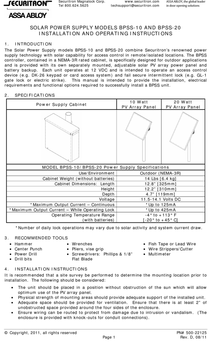
Other Assa Abloy Power Supply manuals

Assa Abloy
Assa Abloy Securitron AQD5 Series User manual

Assa Abloy
Assa Abloy Securitron AQL102 User manual

Assa Abloy
Assa Abloy SECURITRON BPSM-12-6 User manual

Assa Abloy
Assa Abloy SECURITRON BPSS-10 User manual

Assa Abloy
Assa Abloy Securitron AQL4 User manual

Assa Abloy
Assa Abloy Securitron AQD6 Series User manual

Assa Abloy
Assa Abloy Securitron BPS-12-1 User manual

Assa Abloy
Assa Abloy effeff 1006 Series User manual

Assa Abloy
Assa Abloy Securitron AQE30E User manual

Assa Abloy
Assa Abloy Securitron AQL6 User manual