Beghelli NVG User manual

NVGEW V90800L / V90801L / V90802L / V90803L / V90805L
INSTRUCTION MANUAL
E09060060 / 1494.0409E / V. 1.8
Beghelli PRÄZISA GmbH
Page 1 of 5
Emergency supply device NVG for the LOGICA system
Type: NVGEW
Order codes: V90800L (6,5 Ah)
V90801L (13 Ah)
V90802L (28 Ah)
V90803L (40 Ah)
V90805L (55 Ah)
Technical data:
Mounting: surface wall mounting
Body: ABS, plastic
Mains supply: 198 V AC to 254 V AC / 50 Hz
Ambient temperature: 0 °C to 40 °C
Output voltage (mains operation): 230 V AC / 50 Hz (sinus voltage)
Output voltage (emergency operation): 230 V AC / 50 Hz (square voltage)
or
230 V DC / 0 Hz
TOTAL OUTPUT POWER (OUT1 + OUT2):
Incandescent lamp: max. 120 W
Fluorescent lamp: max. 120 W
- inductive control gear: adjust „AC OUT“ (see page 3)
- electronic control gear: adjust „DC OUT“ (see page 3)
Output circuit fuses: 250 V / 1 A / time-lag / 5x20 mm
Battery type: lead acid battery
Battery block voltage: 12 V
Battery capacity: 6,5 Ah / 13 Ah (2x 6,5 Ah) / 28 Ah / 40 Ah / 55 Ah,
depending on model
Duration (emergency lighting) : 1 h or 3 h (adjustable)
V
90800L
V90801L V90802L
V
90803L
V
90805L
At the model V90805L the NVG body must be
mounted in a way that the connection poles of the
battery block are are located at the top!
NVGEW V90800L / V90801L / V90802L / V90803L / V90805L
INSTRUCTION MANUAL
E09060060 / 1494.0409E / V. 1.8
Beghelli PRÄZISA GmbH
Page 2 of 5
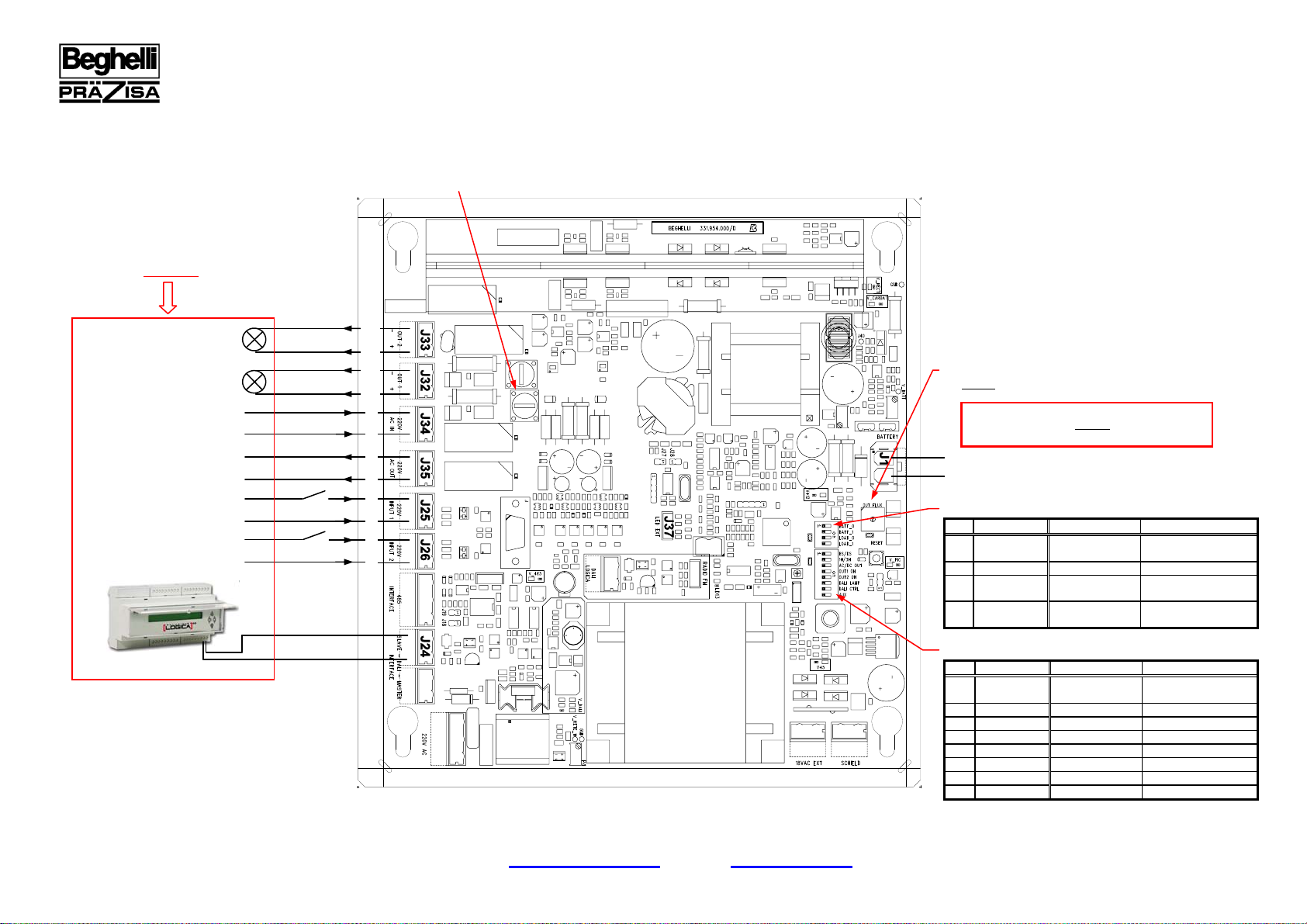
OUT1
OUT2
230V AC IN
DIP Name OFF ON
1 BS/DS
non-maintained
operation (BS) maintained
operation (DS)
2 1H/3H duration 1 h duration 3 h
3 AC/DC OUT AC DC
4 OUT1 ON OUT1 OFF OUT1 ON
5 OUT2 ON OUT2 OFF OUT2 ON
6 DALI LAMP not used not used
7 DALI CTRL not used not used
8 AUX normal operation not allowed
SW1:
SW2:
DIP Name OFF ON
1 BATT_0
battery capacity
< 13 Ah battery capacity
> 13 Ah
2 BATT_1 not used not used
3 LOAD_0 OUT1 power
> 10 W OUT1 power
< 10 W
4 LOAD_1 OUT2 power
> 10 W OUT2 power
< 10 W
ROTARY SWITCH SW3:
set always in position “0”
FUSES:
250 V / 1 A / time-lag / 5x20 mm
230V AC OUT
(max. 300 W, bridgedwith J34
)
INPUT 1(230
V
A
C)
(
li
g
ht switch ON/OFF for OUT1
)
INPUT 2 (230
V
A
C)
(light switch ON/OFF for OUT2)
A
BATTERY (12 V)
L
N
L
N
* Consider REMARKS on page 3 !
+
-
ATTENTION
CONNECT LOAD AT FIRST BEFORE SWITCHING ON NET
AND BATTERY VOLTAGE
D
L
N
L
N
N/-
L/+
N/-
L/+
optional

NVGEW V90800L / V90801L / V90802L / V90803L / V90805L
INSTRUCTION MANUAL
E09060060 / 1494.0409E / V. 1.8
Beghelli PRÄZISA GmbH
Page 3 of 5
E-mail: [email protected] Internet: www.beghelli.de
* REMARKS:
ATTENTION !
>CONNECT LOAD AT FIRST BEFORE SWITCHING ON NET AND BATTERY VOLTAGE
>TOTAL OUTPUT POWER (OUT1 + OUT2):
Incandescent lamps:
max. 120 W
Fluorescent lamps with inductive control gear:
max. 120 W,
the DIP switch SW1 must be set at „AC/DC OUT“ in the position OFF,
possibly present compensation capacitors must be removed from J32 and J33,
compensation capacitors can be connected to J34 or J35 if required
Fluorescent lamps with electronic control gear:
max. 120 W,
the DIP switch SW1 must be set at „AC/DC OUT“ in the position ON
>USE WITHOUT CENTRAL (LOGICA SOR LOGICA FM):
The DIP switch SW1 must be set at „BS/DS“ in the position OFF for the use of light switches on J25 / J26 or to implement the operating mode non-
maintained operation. The DIP switch SW1 must be set at „BS/DS“ in the position ON to implement the operating mode maintained operation.
>USE WITH CENTRAL (LOGICA SOR LOGICA FM):
The function AUTODIMMER must be assigned over the central (Logica S or Logica FM) to the NVG for the use of light switches on J25 / J26. The position
of the DIP switch 1 on SW1 is not relevant.
CAPACITORS
MAGNETIC CONTROL GEAR
NVG
STARTER
STARTER
ILLUMINANT
230 V AC IN OUT2
OUT1
ILLUMINANT
MAGNETIC CONTROL GEAR

NVGEW V90800L / V90801L / V90802L / V90803L / V90805L
INSTRUCTION MANUAL
E09060060 / 1494.0409E / V. 1.8
Beghelli PRÄZISA GmbH
Page 4 of 5
E-mail: [email protected] Internet: www.beghelli.de
LED-SIGNAL (t in ms) MEANING
CONSTANT GREEN LIGHTED LED:
normal operation,
battery charged
GREEN BLINKING LED:
normal operation,
battery charging or function test
CONSTANT GREEN LIGHTED LED
+
GREEN BLINKING LED:
duration test
CONSTANT GREEN LIGHTED OR BLINKING LED
+
ONE TIME RED BLINKING LED:
battery charge-failure or battery failure at function/duration test
CONSTANT GREEN LIGHTED OR BLINKING LED
+
TWO TIMES RED BLINKING LED:
failure on output circuit
CONSTANT GREEN LIGHTED OR BLINKING LED
+
THREE TIMES RED BLINKING LED:
failure at DC/DC converter
CONSTANT GREEN LIGHTED OR BLINKING LED
+
THREE TIMES ORANGE BLINKING LED:
loss of the synchronicity at test procedure
(NVG off because of a too long mains failure)
To remedy this failure, a test synchronisation and a reset must
be done (by central or autotest command).
GREEN GREEN GREEN
250 250250 250 250250 250 250250
RED
250 250250
RED
GREEN GREEN GREEN
250 250250250 250250 250 250250 250 250250
250 250250 250 250250
GREEN GREEN GREEN RED RED
250 250250 250 250250250 250250 250 250250 250 250250
RED RED RED
250 250250 250 250250 250 250250
GREEN GREEN RED RED RED
250 250250 250 250250 250 250250250 250250 250 250250 250 250250
ORANGE ORANGE ORANGE
250 250250 250 250250 250 250250
ORANGE ORANGE ORANGE
GREEN GREEN GREEN
250 250250 250 250250 250 250250250 250250 250 250250 250 250250
ON
OFF
ON
OFF
ON
OFF
ON
OFF
ON
OFF
ON
OFF
ON
OFF
ON
OFF
ON
OFF
GREEN
GREEN
ON
OFF
GREEN GREEN GREEN
250 250250 250 250250 250 250250
OFF
ON
2250
GREEN
GREEN
RED
GREEN RED
GREEN
GREEN
2250
2250
2250
2250
2250
NVGEW V90800L / V90801L / V90802L / V90803L / V90805L
INSTRUCTION MANUAL
E09060060 / 1494.0409E / V. 1.8
Beghelli PRÄZISA GmbH
Page 5 of 5
E-mail: [email protected] Internet: www.beghelli.de
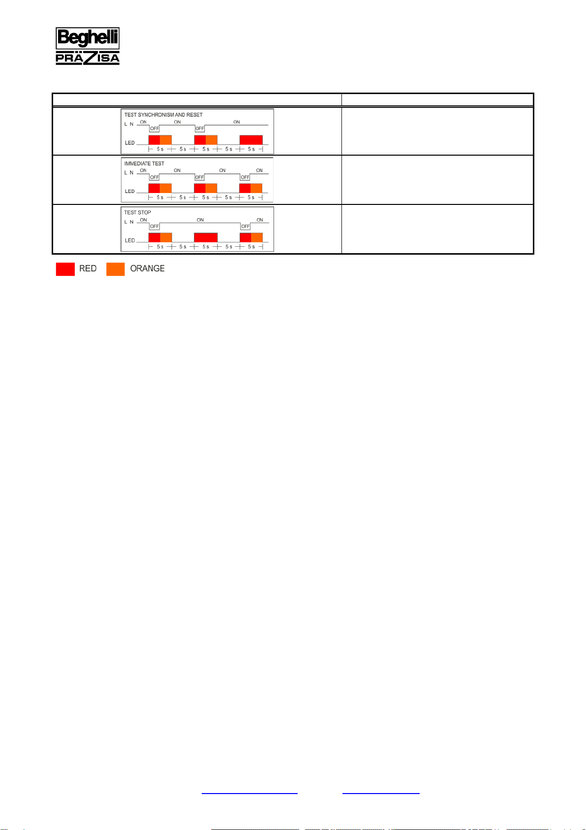
AUTOTEST COMMANDS:
DURATION / INTERVALS COMMAND
test synchronism and reset
immediate test (duration)
test stop (all tests will be stopped)
This manual suits for next models
5
Table of contents
Other Beghelli Power Supply manuals


