Friedrich Lütze GmbH
Bruckwiesenstr. 17-19
71384 – Weinstadt – Germany
Tel.: +49 (0)7151 6053-0
Fax.: +49 (0)7151 6053-271
Friedrich Lütze GmbH
Bruckwiesenstr. 17-19
71384 – Weinstadt – Germany
Tel.: +49 (0)7151 6053-0;
Fax.: +49 (0)7151 6053-271
Konformitätserklärung / Declaration of conformity
Hiermit erklären wir, das die Produkte mit den EU Standards
übereinstimmen und das E Zeichen tragen dürfen.
Operating Instructions
Read Instructions!
Before working with this unit, read these instructions carefully and completely. Make sure that you have understood all the
information! Warning !
Before any installation, maintenance or modification work: Disconnect your system from the supply network. Ensure that cannot
be re-connected inadvertently! Before start of operation:
Warning! Improper installation / operation impair safety and result in operational difficulties or complete failure of the unit. The unit
must be installed and put into service by appropriately qualified personnel. Compliance with the relevant regulations must be
ensured. Before operation start, the following conditions must be ensured, in particular:
•Connection to main power supply in compliance with VDE01000 and EN50178.
•With stranded wires: all strands must be secured in the terminal blocks (potential danger of short
circuit).
•Unit and power supply cables must be properly fused; if necessary a manually controlled disconnecting
element must be used to disengage from supply mains.
•The non-fused earth conductor must be connected to the " PE " terminal (protection class 1).
•All output lines must be rated for the power supply output current and must be connected with the
correct polarity.
•Sufficient air-cooling must be ensured.
In operation: No modifications: As long as the unit is in operation do not modify the installation! The same applies also to the
secondary side. Risk of electric arcs and electric shock (fatal)! Only disconnect pluggable connectors when the power is off!
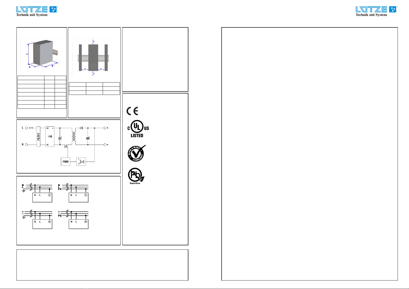
Convection cooling: Don´t cover any ventilation holes! Leave sufficient space around the unit for cooling! See Fig. 2
Warning: High Voltage!
High voltage! Store energy! The unit contains unprotected conductors carrying a lethal high voltage, and components storing
substantial amounts of energy. Improper handling may result in an electric shock or serious burn! The unit must not be opened
except appropriately trained personnel! Do not introduce any object into the unit! Keep away from fire and water!
Application : This unit is a primary switched-mode power supply designed for use in panel-board installations or building-in
applications where access to the supply is restricted (shock- hazard protection). It must only be installed and put into service by
appropriately qualified personnel.
Mounting : Permissible mounting position: see Fig.2. The indicated space is a mandatory !
Snap on rail : Tilt the unit slightly rearwards. Fit the unit over top hat rail. Slide it downward until it hits the stop. Press against the
bottom front side for (see Fig. 4) locking. Shake the unit slightly to check the locking action.
LED indication: „DC OK“ green LED : on = all In-/Output parameter are ok.
Alarm contact: not implemented.
Potentiometer : Setting the output voltage. It´s not allowed to drive the power supply with more than the nominal power (U
N
x I
N
)
Redundancy and parallel operation : Redundant and parallel operation is possible with external decoupling diodes.
Connection / Internal fuse:
•Data for permitted loads, cable cross-sections and stripping: see enclosed leaflet " Technical Data "
(See Fig. 3).
•Use only commercial cables designed for the indicated voltage and current values!
•With flexible cables: make sure that all stranded cable are secured in the terminal.
•Ensure proper polarity at output terminals!
Grounding: •Using Class 2 power supplies a PE connection is not necessary. The power supply can be used in
SELV and PELV circuits. Using Class 1 power supplies a PE connection on the primary side is a
mandatory.To be in compliance with all EMC and safety requirements (CE, approvals), operation of
Class 1 power supplies are only allowed with a PE connection.
•Secondary side is not grounded; if necessary the “plus” or “minus” terminal can be grounded optionally.
Internal fuse:
The internal input fuse serves to protect the unit and must not be replaced by the user. In case of an internal defect, the unit must
be returned to the manufacturer for safety reasons.
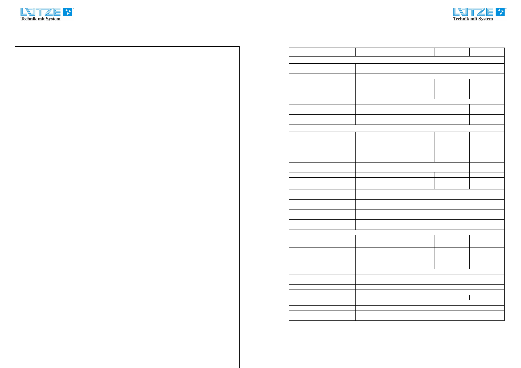
Technical Data:
All specifications are typical at nominal line, full load,25°C; unless otherwise noticed.
Type / model CPSF1-40-24
CPSF1-80-24
Eingang / Input
Eingangsspannungsbereich
Input voltage range AC 90V – 264V / DC 100V – 345V
Frequenz / frequency 47 Hz – 63Hz
Eingangsstrom @ Un
Input current @ Un 0,90A @ AC 120V
0,50A @ AC 230V 1,40A @ AC 120V
0,85A @ AC 230V
Einschaltstrom
Inrush current < AC 30A < AC 30A
PFC > 0,6 @ Vollast / full load
Interne Sicherung
Internal fuse
1
T 2A / 250V
Externe Sicherung
External fuse Automat C4A; MCB C4A
Ausgang / Output
Nennspannung Ausgang
Nominal output voltage DC 24V +/- 1% DC 24VDC
(23,5V….27,5V)
Max. Ausgangsstrom @ AC 240V
Max. output current @ AC 240V
2
3,5A 4,0A
Nennstrom Ausgang
Nominal output current 2,0A 3,3A
Lastregelung
Load regulation < 1%
Ripple @ Imax < 80mV pp <50mVpp
Netzausfallüberbrückung
Hold up time @ full load > 60ms @ AC 230V
> 40ms @ AC 230V
Überlast / Kurzschlußschutz
Overload / short circuit protection HICCUP
Übertemperatursicherung
Over temperature protection JA / yes
Status Anzeige (DC ON)
Status indication (DC ON) JA / yes
Parallel Betrieb
Parallel operation Ja, mit externer Diode / yes with external diode
Allgemeine Daten / general data
Effektivität
efficiency > 86% @ AC 230V
> 88% @ AC 230V
Verlustleistung / Dissipated power < 8W < 11W
Betriebstemperatur
Operation temperature -20°/+70°C -20°C/+70°C
Derating >50°C : 0,35W/°C >55°C : 0,9W/°C
Isolationsspannung / isolation voltage
AC 3kV / 1min.
Schutzart / IP rating IP20 (IEC529, EN60529)
Verschmutzungsgard /pollution degree
II ; (IEC 664-1)
Sicherheitsklasse / safety class Class II
Gehäusematerial / housing material Noryl UL 94-0
Gewicht / weight 250g
Anschlusstechnik / termination Schraubanschlus / screw terminal 2,5mm
Montage / mounting TS 35 acc. IEC 60715
Standards / standards UL 508C, IEC 850, EN 60950, EN 50081-1, EN 50082-2, EN 55022 Class B
EN 61000-4-2/3/4/5/6/11, EN 61000-3-2, EN 55011B, EN 55022 class B
(1) Sicherung ist nicht austauschbar; Fuse is not replaceable
(2) Bei DC 110V Betrieb ist reduziert sich der Ausgangsstrom um 25%
with an operation voltage of DC 110V the output current is reduced by 25%
Allgemein : Alle angegebenen Daten sind typisch und wenn nicht anders vermerkt gültig bei 230V am Eingang und einer
Umgebungstemperatur von 25°C.
General : all specified datas are typical and unless otherwise specified
measured at 230V input and 25°C environmental
temperature.