manuals.online logo
Brands
  1. Home
  2. •
  3. Brands
  4. •
  5. NewMar
  6. •
  7. Power Supply
  8. •
  9. NewMar STARTGUARD NS-12-20 User manual

NewMar STARTGUARD NS-12-20 User manual

Model: NS-12-20
INSTALLATION/OPERATION MANUAL
USA Headquarters
P.O. Box 1306
Newport Beach, CA 92663
Shipping:
2911 West Garry Ave.
Santa Ana, CA 92704
Phone: 714-751-0488
Fax: 714-957-1621
e-mail: [email protected]
www.newmarpower.com
Euro Warehouse
Holland
Phone: +31-35-603-2494
Fax: +31-35-603-2149
E-mail:[email protected]
LIMITED WARRANTY
NEWMAR warrants with the original purchase of products sold by NEWMAR, that they shall be
free from defects and material and workmanship for two years from the date of purchase.
In the event of a product failure caused by defect of material or workmanship you must return
the entire product with original packing if possible, freight pre-paid, to the place of purchase or
to NEWMAR, 2911 W. Garry Avenue, Santa Ana, California 92704. Besides paying to send back
the product, you must include proof of purchase reflecting where the product was purchased,
the date of purchase and a written explanation of the alleged defect. If this product is deter-
mined to be defective by NEWMAR, we will repair the product and ship it back to you without
charge. If non-repairable within 30 days, we will ship an equivalent or better replacement
product or provide you with a refund of your purchase price.
Repairs or adjustments to be made on the defective product shall be determined by NEWMAR in
its sole discretion. If you have any questions concerning this Limited Warranty, contact us at
the above address or call Customer Service at 1-714-751-0488.
This Limited Warranty does not apply to products that have not been installed properly or
maintained adequately. This Limited Warranty does not apply to damage through accident,
negligence, misuse, abuse, or normal wear and tear. Further, this warranty does not cover
products that have been altered or modified from their original sale condition. For information
regarding proper installation, please consult the instructions enclosed with the product. You
may contact NEWMAR or an authorized retailer for additional installation instructions. It is your
responsibility to check the product upon receipt for any damage during shipping and to contact
the carrier or shipper regarding such damage. No person including any NEWMAR dealer, is
authorized to assume any further liability for NEWMAR beyond this Limited Warranty, in
connection with products sold by NEWMAR. A customer’s sole and exclusive recourse against
NEWMAR is this Limited Warranty, regardless of a customer’s recourse against a seller.
THERE ARE NO WARRANTIES EXPRESS OR IMPLIED WHICH EXIST BEYOND THE TERMS OF
THIS LIMITED WARRANTY. THIS LIMITED WARRANTY IS NEWMAR’S SOLE OBLIGATION TO
YOU FOR THIS PRODUCT AND CONSTITUTES YOUR EXCLUSIVE REMEDY UNDER THE LAW.
NEWMAR SHALL NOT BE LIABLE FOR ANY INCIDENTAL, CONSEQUENTIAL OR INDIRECT
DAMAGES CAUSEDASARESULT OF ANY DEFECT IN WORKMANSHIPOR MATERIAL. LIABILITY
IS LIMITED TO REPAIR OR REPLACEMENT OF THIS PRODUCT. NEWMAR IS NOT RESPONSIBLE
FOR ANY DAMAGE THIS PRODUCT CAUSES TO ANY OTHER EQUIPMENT OR ANY OTHER
PRODUCT.
Some states do not allow limitations in how long an implied warranty may last, so the above
limitation may not apply to you. Also some states do not allow the exclusional limitation of
incidental or consequential damages so the above limitation or exclusion may not apply to you.
Finally, this warranty gives you specific legal rights; however, you may also have other rights
which vary from state to state.
M-NS1220-A
As of June 2003
TYPICAL NS-12-20 STARTGUARD WIRING
ToolsRequired:Volt/Ohm meter (V.O.M.), 12 volt power source, 10 K ohm resistor.
1) Check for continuity in the input fuse with the ohm meter. If the fuse is blown, replace with
anotherofthe same type and value. (See previous section, FUSE REPLACEMENT.)
Ifthe StartGuard is blowing fuses repeatedly, check tomake sure your load does not exceed
20 amps. If the fuses continue to blow and you are certain the StartGuard is not being
overloaded, return the unit to NEWMAR for service.
2)Disconnectallwiring to the StartGuard.
3) Connect the 10 K ohm resister between the (+) and (-) OUTPUT terminals. Note: If you
check voltage on the output without the resistor attached you will read some output
voltage. This is due to reverse diode leakage and is normal. Use the volt meter to measure
thevoltageontheOUTPUT terminals. With the resistor wired across the output terminals,
youshouldmeasurelessthan1volt.
4) Now apply 12 VDC from your power source (power supply or 12 volt battery) across the
STARTER #1 and INPUT (-) terminals. (Connect power supply (+) to STARTER terminal
and power supply (-) to INPUT (-)). You should hear an audible click and the voltmeter
should read 12.4 - 12.7 VDC. Repeat this step with the input power applied across the
STARTER #2 and INPUT (-) terminals. If applying 12 VDC power to either of these terminals
does not bring the internal battery on-line, the unit should be returned to NEWMAR for
service.
5)Iftheinternal battery does come on-line but the voltmeter indicates less than 12 VDC,
recharge the battery with an input voltage of 13.8 - 14.8 VDC for 3 - 4 hours. Then discon-
nect the input, wait 10 minutes, and repeat steps 2 through 4. If you still are not getting a
normal 12.4 - 12.7 VDC reading, the battery must be replaced. (See previous section,
BATTERYREPLACEMENT)
* * Recommended; must be
supplied by installer
* *
* *
+
l
+
l
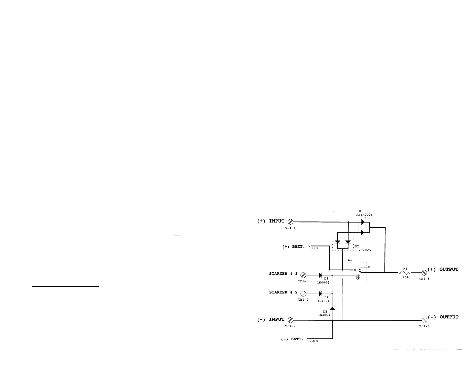
In order to operate, the StartGuard must “see” +12 VDC at one of the two “STARTER”
terminalswheneverthestarterisengaged.AttachthesensewiretotheStartGuard,as
above,thenroutethe sense wiring either directly to the ignition switch or to the starter
solenoid,as shown in the diagram. Each lead must be attachedtoa terminal which receives
+12 VDC only when the starter is engaged. The second sense terminal is provided only for
vesselsorvehicleswithdualenginesandmaybeignoredinsingleengineapplications.
Sense Wiring
- Use any gauge from #12 AWG (4mm) to # 18 AWG (2mm)
III) OPERATION
Operation of the StartGuard is automatic. Whenever 12 VDC is sensed on either of the
“STARTER”terminals,theinternalrelaywillcloseandbringtheinternalbatteryon-lineto
providesupplementalvoltagetothesensitiveelectronicdevice.
When the starter is disengaged and there is no longer 12 VDC present on either terminal,
therelaywill open, disengaging the battery.
TheStart-Guardbattery relies on your main battery system voltage for recharging. There-
fore, there should always be 12 VDC (nominal) present on the +/- input terminals. Charging
the StartGuard battery requires an input voltage of 13.8 - 14.8 VDC for about 3-4 hours
minimumpermonth.(Thesevoltagesareproducedbyanytypical12 volt alternator.)
Maintenancevoltages above 13.4 VDC will prevent anyself-discharge.
Important: Batteries can be permanently damaged if left in a discharged state for an
extended period of time. If the StartGuard is to be put into storage, the internal battery must
be charged first. Leaving it hooked up to your main battery system for at least 48 hours
before storing it should be sufficient.
IV) BATTERY REPLACEMENT
Toguarantee properoperation,theStartGuard battery should be replacedatleastevery 5
years, or as soon as it will no longer hold a charge.
To determine the age of the battery in your StartGuard, check the quality control sticker on
the end of the unit. The first four digits of the serial number (designated "S/N") refer to the
year and month of manufacture. For instance, a unit with a serial number starting "0135"
was manufactured the 35th week of 2001. Be sure to mark the date of replacement on this
stickerforfuturereference.
Caution: Take care to ensure that you do not short the battery terminals during installation.
The resulting high current can melt wires and cause other damage to the unit.
1) Turn off power to the input wiring and disconnect all input and output connections to the
Start-Guard.Removethe unit from the mounting surface.
2)Usingaphillipsscrewdriver, remove the four corner screw/lockwasher sets from the top of
the unit and remove the top cover.
3)Disconnect the red and black power leads from thebatteryterminals.
4) Remove and dispose of the battery properly and according to local codes. Although the
batteryissealed,it is a lead-acid type and there may be restrictions on its disposal.
5) Set the new battery in place in the unit. Note that the terminals are are color coded and
marked “+” (red) and “-“ (black). Reattach the power leads, red to “+” and black to “-“.
6) Replace the top cover and reinstall on the mounting surface.
V) “EXERCISING” NEW BATTERIES
Newbatteriesmayneedto be “exercised” once before they will be capable of delivering their
fullratedcapacity.Takethefollowing steps if you wish toexercisethenewbattery prior to
puttingtheStartGuardbackinservice.
Requirement: 12 volt power source, 2-3 amp 12 volt load
1)Ensurethatallinputwires,includingthestartersenseleadsaredisconnected.
2) Connect the load to the (+) and (-) OUTPUT terminals.
3) Apply 12 volts to either the STARTER #1 or #2 terminal and the INPUT ( ) terminal to
activatetheinternalrelay and bring the battery on-line with the load.
4) Let the load draw current from the battery for about 15 minutes.
5) Disconnect the load, reconnect all input wiring and charge the StartGuard for 3-4 hours at
13.8-14.8 VDC.
VI) FUSE REPLACEMENT
The StartGuard is equipped with an internal fuse to protect wiring from overloads and short
circuits. Should the fuse need replacement it must be with another of the same type and
value: ATC blade type, 20 amps. A spare fuse has been provided with the unit. If you cannot
locatethis fuse and cannot find one locally, spare fusesmay also be obtained from the
factory.
Toreplacetheinternalfuse:
1) Turn off power to the StartGuard input and disconnect the input, output and starter
connections . Remove the unit from the mounting surface.
2)Usingaphillips screwdriver, remove the four corner screw/lockwasher sets from the top of
the unit and remove the top cover.
3) The fuse is located in the center of the printed circuit board (marked “20”). Use a pair
of needle-nose pliers to remove it and to install the new fuse.
4) Replace the top cover and reinstall on the mounting surface.
VII) TEST AND TROUBLESHOOTING
If you suspect that the StartGuard is not operating properly, you may use the following
procedure to verify whether or not there is a problem.
I) GENERAL INFORMATION
TheabruptDCsystem voltage drop that accompanies engine starting can cause micropro-
cessor-drivenelectronicsaboard vehicles or vessels to “dump” programmed memory. In
mobilecommunications,thiscanresultintransmissionerrorsandlossof“handshake”in
datatransmitters,orcause programmable radios to re-set at incorrect channels. In marine
applications,GPS, SAT-NAV or other navigation/communication transceivers may lose
signallockor“crash” resulting in a loss of pre-programmed waypoints or fequencies.
StartGuardsolves these problems by providing supplemental powertosensitiveelectronics
whiletheenginesarebeingcranked.Itcontainsa sealed rechargeable battery which is
switchedon-linewhenever the starter switch or solenoid is engaged. When the engine is
runningandsystemvoltage returns to normal, StartGuard automatically goes off-line and the
internalbatteryisrechargedbythealternatorandreadiedforthenextstartsequence.Two
separatesenseterminals are provided for vessels or vehicles withdualenginesor ignition
switches.
Theinternal battery is replaceable. Typicallifeis5-7 years.
II) INSTALLATION
Thefollowingitemsareprovided.Ifanythingismissingfromthepackaging,pleasecontact
the factory for replacement: (1) 20 amp StartGuard unit, (4) #10-3/4" mounting screws, (1)
spare20ampfuse,(1)Customer Satisfaction/Warranty card
Mounting
Mount the StartGuard in any convenient location, such as under the dash or console, using
thefour mounting screws provided or # 10 bolts.The case is electrically isolated and does
not require grounding, therefore mounting on either a metal or non-metal surface is accept-
able.Theinternalbatteryissealed,sotheStartGuardmaybeorientedinanyposition.Note:
mounting under an engine hood or other high-heat environment is not recommended.
IMPORTANT: Although the StartGuard is constructed of materials which are resis-
tant to the corrosive effects of moisture in the environment, it is not waterproof. Do
not mount the StartGuard where there is a possibility of water entering the unit.
Evidence of water entry into the unit will void the warranty.
Wiring
Input from the power source to the electronics must be routed through the StartGuard. For
optimum performance, wiring from the power source to the StartGuard and from the
StartGuardtotheelectronicdevice(s) being protected should not exceed 10 feet (each way).
Input/Output Power Wiring
- For wire lengths up to 5 feet, use #14 AWG (2.5mm) wire.
- For wire lengths 5-10 feet, use #12 AWG (4mm) wire.
The wiring to the StartGuard should be over-current protected at the power source. If it has
not already been done, install a 25 amp circuit breaker or fuse at the power source. Shut off
or disconnect power to the input wires before proceeding.
TheStartGuardisequippedwith a wire-ready terminal block with “capture” screw terminals.
Removetheyellowterminalblockcoverandloosentheterminalscrews.Stripthewireends
about 1/4" and attach them to the terminal block as shown in the diagram (opposite page).
VIII)SPECIFICATIONS
Input Voltage: 13.8 - 14.8 VDC nominal, 15.5 VDC max.
Relay Activation
Input Voltage: 7 - 15 VDC
Output: 20 amps max
Battery: 12 VDC, 4.0 amp/hour, sealed rechargeable,
3-5 year life (typical)
Back-Up Capacity
(Fully Charged: 20 amps for one minute
15 amps for 2 minutes
Operating Temperature
Range: 0-40° C
Winter Storage
Temperature Range -20° to +40° C
Dimensions: 8.25" x 4.9" x 3.5"
Weight: 5.5 lbs.
IX) SCHEMATIC DIAGRAM

Other NewMar Power Supply manuals

NewMar Phase Three PT-CE Series User manual

NewMar

NewMar Phase Three PT-CE Series User manual

NewMar PM-24-80 User manual

NewMar

NewMar PM-24-80 User manual

NewMar PM-12-40 User manual

NewMar

NewMar PM-12-40 User manual

NewMar MDP-25 User manual

NewMar

NewMar MDP-25 User manual

NewMar SPS 12-20 User manual

NewMar

NewMar SPS 12-20 User manual

NewMar Centurion III C3RS-48-124 User manual

NewMar

NewMar Centurion III C3RS-48-124 User manual

NewMar power-pac User manual

NewMar

NewMar power-pac User manual

NewMar Centurion II User manual

NewMar

NewMar Centurion II User manual

NewMar Centurion II User manual

NewMar

NewMar Centurion II User manual

NewMar EP 12-10 User manual

NewMar

NewMar EP 12-10 User manual

NewMar Centurion CR48-10 User manual

NewMar

NewMar Centurion CR48-10 User manual

NewMar PM-12-40A PM Series User manual

NewMar

NewMar PM-12-40A PM Series User manual

NewMar C2R-2000 User manual

NewMar

NewMar C2R-2000 User manual

NewMar POWER-PAC User manual

NewMar

NewMar POWER-PAC User manual

NewMar PT-20CE User manual

NewMar

NewMar PT-20CE User manual

NewMar RM2048HE User manual

NewMar

NewMar RM2048HE User manual

NewMar Commander II Series User manual

NewMar

NewMar Commander II Series User manual

Popular Power Supply manuals by other brands

Altronix ALTV244UL3 Series installation guide

Altronix

Altronix ALTV244UL3 Series installation guide

3B SCIENTIFIC PHYSICS 1002775 instruction sheet

3B SCIENTIFIC PHYSICS

3B SCIENTIFIC PHYSICS 1002775 instruction sheet

Gallagher 3E3446 M5800i instructions

Gallagher

Gallagher 3E3446 M5800i instructions

Westermo PS-60 user guide

Westermo

Westermo PS-60 user guide

Mastech HY1803D user manual

Mastech

Mastech HY1803D user manual

ITW Simco-Ion Chargemaster VCM30 Series Installation and operating instructions

ITW

ITW Simco-Ion Chargemaster VCM30 Series Installation and operating instructions

American Magnetics 601 Installation, operation and maintenance instructions

American Magnetics

American Magnetics 601 Installation, operation and maintenance instructions

ODA EX Series user manual

ODA

ODA EX Series user manual

Gallagher M5000i instructions

Gallagher

Gallagher M5000i instructions

Rigol DP831 user guide

Rigol

Rigol DP831 user guide

Monacor PSS-3000E operating instructions

Monacor

Monacor PSS-3000E operating instructions

INIM IPS24160G manual

INIM

INIM IPS24160G manual

BOC Edwards CV-6SL instruction manual

BOC Edwards

BOC Edwards CV-6SL instruction manual

Vimar Elvox 40100 installation instructions

Vimar

Vimar Elvox 40100 installation instructions

Nordson Prodigy iControl instruction sheet

Nordson

Nordson Prodigy iControl instruction sheet

VIPA PS 307S_Co manual

VIPA

VIPA PS 307S_Co manual

BCP PUOU1CBK How to install

BCP

BCP PUOU1CBK How to install

Vimar ELVOX 6923 quick start guide

Vimar

Vimar ELVOX 6923 quick start guide

manuals.online logo
manuals.online logoBrands
  • About & Mission
  • Contact us
  • Privacy Policy
  • Terms and Conditions

Copyright 2025 Manuals.Online. All Rights Reserved.