Beha-Amprobe AT-6000-EUR Series User manual

KOMETEC Karl Oelkers e.K.
Mess- und Prüfgeräte · Shop
Mozartstr. 10 · D-88097 Eriskirch
T: 07541 / 955-1313 · F: 07541 / 955-1131


AT-6000-EUR
Advanced Wire Tracer
AT-6020-EUR
AT-6030-EUR
User Manual
3/2018, Rev A
©2018 Beha-Amprobe.
All rights reserved.
English

Limited Warranty and Limitation of Liability
Your Beha-Amprobe product will be free from defects in material and workmanship for
two years from the date of purchase unless local laws require otherwise. This warranty does
not cover fuses, disposable batteries or damage from accident, neglect, misuse, alteration,
contamination, or abnormal conditions of operation or handling. Resellers are not
authorized to extend any other warranty on the behalf of Beha-Amprobe. To obtain service
during the warranty period, return the product with proof of purchase to an authorized
Beha-Amprobe Service Center or to an Beha-Amprobe dealer or distributor. See Repair
Section for details. THIS WARRANTY IS YOUR ONLY REMEDY. ALL OTHER WARRANTIES
- WHETHER EXPRESS, IMPLIED OR STATUTORY - INCLUDING IMPLIED WARRANTIES OF
FITNESS FOR A PARTICULAR PURPOSE OR MERCHANTABILITY, ARE HEREBY DISCLAIMED.
MANUFACTURER SHALL NOT BE LIABLE FOR ANY SPECIAL, INDIRECT, INCIDENTAL OR
CONSEQUENTIAL DAMAGES OR LOSSES, ARISING FROM ANY CAUSE OR THEORY. Since some
states or countries do not allow the exclusion or limitation of an implied warranty or of
incidental or consequential damages, this limitation of liability may not apply to you.
Repair
All Beha-Amprobe tools returned for warranty or non-warranty repair or for calibration
should be accompanied by the following: your name, company’s name, address, telephone
number, and proof of purchase. Additionally, please include a brief description of the
problem or the service requested and include the test leads with the product. Non-warranty
repair or replacement charges should be remitted in the form of a check, a money order,
credit card with expiration date, or a purchase order made payable to Beha-Amprobe.
In-warranty Repairs and Replacement – All Countries
Please read the warranty statement and check your battery before requesting repair.
During the warranty period, any defective test tool can be returned to your Beha-Amprobe
distributor for an exchange for the same or like product. Please check the “Where to
Buy” section on beha-amprobe.com for a list of distributors near you. Additionally, in the
United States and Canada, in-warranty repair and replacement units can also be sent to an
Amprobe Service Center (see address below).
Non-warranty Repairs and Replacement – Europe
European non-warranty units can be replaced by your Beha-Amprobe distributor for a
nominal charge. Please check the “Where to Buy” section on beha-amprobe.com for a list of
distributors near you.
Beha-Amprobe
Division and reg. trademark of Fluke Corp. (USA)
Germany*
In den Engematten 14
79286 Glottertal
Germany
Phone: +49 (0) 7684 8009 - 0
beha-amprobe.de
United Kingdom
52 Hurricane Way
Norwich, Norfolk
NR6 6JB United Kingdom
Phone: +44 (0) 1603 25 6662
beha-amprobe.com
The Netherlands - Headquarters**
Science Park Eindhoven 5110
5692 EC Son
The Netherlands
Phone: +31 (0) 40 267 51 00
beha-amprobe.com
*(Correspondence only – no repair or replacement available from this address. European
customers please contact your distributor.)
**single contact address in EEA Fluke Europe BV

1
AT-6000-EUR Series
CONTENTS
1. PRECAUTIONS AND SAFETY MEASURES ............................................................. 2
2. KIT COMPONENTS................................................................................................. 5
2.1 AT-6000-RE Receiver ......................................................................................................5
2.2 AT-6000-TE Transmitter .................................................................................................7
2.3 CT-400-EUR Signal Clamp (AT-6030-EUR Kit) ...............................................................10
3. MAIN APPLICATIONS ............................................................................................ 11
3.1 Tracing Energized and De-energized Wires .................................................................12
3.2 Identifying Breakers and Fuses (energized and de-energized) ...................................16
3.3 Non-contact Voltage Mode (NCV) and Passive Tracing................................................18
4. SPECIAL APPLICATIONS ........................................................................................ 19
4.1 RCD Protected Circuit Wire Tracing..............................................................................19
4.2 Finding Breaks/Opens ...................................................................................................19
4.3 Finding Shorts ...............................................................................................................20
4.4 Tracing Wires in Metal Conduit ...................................................................................20
4.5 Tracing Non-Metallic Pipes and Conduits ....................................................................20
4.6 Tracing Shielded Wires ..................................................................................................21
4.7 Tracing Underground Wires..........................................................................................21
4.8 Tracing Low Voltage Wires and Data Cables ...............................................................21
4.9 Sorting Bundled Wires ..................................................................................................22
4.10 Mapping Circuit Using Test Leads Connection ...........................................................23
4.11 Tracing Breakers on System with Light Dimmers .......................................................23
4.12 Signal Clamp - Closed Loop Circuits ............................................................................24
4.13 Signal Clamp - Mapping Circuits..................................................................................25
5. MAINTENANCE - BATTERY AND FUSE REPLACEMENT........................................ 27
6. SPECIFICATIONS..................................................................................................... 30

2
1. PRECAUTIONS AND SAFETY MEASURES
General
For your own safety and to avoid damage to the instrument we suggest you to follow the
procedures listed below:
NOTE: Before and during measurements be diligent to follow the instructions.
• Make sure that the electrical instrument is operating properly before use.
• Before attaching any of the conductors, make sure that the voltage present in the
conductor is in the range of the instrument.
• Keep the instruments in their carrying case when not in use.
• If the transmitter or receiver will not be used for a long time, remove the batteries to
prevent leakage in the instruments.
• Use Beha-Amprobe approved cables and accessories only.
Safety precautions
• In many instances, you will be working with dangerous level of voltage and/or current.
Therefore, it is important that you avoid direct contact with any uninsulated, current
carrying surfaces. Wear appropriate insulated gloves, face protection and protective
clothing in hazardous voltage areas.
• Do not measure voltage or current in wet or damp or dusty places.
• Do not measure in presence of gas, explosive materials or combustibles.
• Do not touch the circuit under test if no measurement is being taken.
• Do not touch exposed metal parts, unused terminals, circuits and so on.
• Do not use the instrument if it seems to be malfunctioning (i.e. if you notice
deformations, breaks, leakage of substances, and absence of messages on the display
and so on).
Safety information
The product complies with:
• UL/IEC/EN 61010-1, CAN/CSA C22.2 No. 61010-1, Pollution Degree 2, Measurement
CAT III 600 V MAX
• IEC/EN 61010-2-033
• IEC/EN 61010-2-032
• IEC/EN 61010-031 (test leads)
• EMC IEC/EN 61326-1
Measurement Category III (CAT III) is applicable to test and measuring circuits connected
to the distribution part of the building’s low-voltage MAINS installation. This part of the
installation is expected to have a minimum of two levels of over-current protective devices
between the transformer and possible connecting points.
CENELEC Directives
The instruments conform to CENELEC Low-voltage directive 2014/35/EC and Electromagnetic
compatibility directive 2014/35/EC.

3
�Warnings: Read Before Using
To avoid possible electric shock or personal injury:
• Use the Product only as specified in this manual or the protection provided by the
instrument might be impaired.
• Avoid working alone so assistance can be rendered.
• Test on a known signal source within the rated voltage range of the Product. Both,
before and after use, to ensure the Product is in good working conditions.
• Do not use the Product in wet or damp environments.
• Do not operate the Product around explosive gas, vapor, or dust.
• Do not use the Product if it appears damaged. Inspect the Product before use. Look for
cracks or missing plastic. Pay particular attention to the insulation around the connectors.
• Inspect the test leads before use. Do not use them if insulation is damaged or metal is exposed.
• Check the test leads for continuity. Replace damaged test leads before using the Product.
• Do not use the Product if it operates incorrectly. Protection may be impaired. When in
doubt, have the Product serviced.
• Have the Product serviced only by qualified service personnel.
• Use extreme caution when working around bare conductors or bus bars. Contact with
the conductor could result in electric shock.
• Do not hold the Product anywhere beyond the tactile barrier.
• Do not apply more than the rated voltage and CAT rating, as marked on the Product,
between the terminals or between any terminal and earth ground.
• Remove test leads from the Product before opening the Product case or battery cover.
• Never operate the Product with the battery cover removed or the case open.
• Never remove the battery cover or open the case of the Product without first removing
the test leads from any live conductor.
• Use caution when working with voltages above 30 V ac rms, 42 V ac peak, or 60 V dc.
These voltages pose a shock hazard.
• Do not attempt to connect to any circuit carrying voltage that may exceed the
maximum range of the Product.
• Use the proper terminals, function, and range for your measurements.
• When using alligator clips and test probes, keep fingers behind the finger guards/
tactile barrier.
• When making electrical connections, connect the common test lead before
connecting the live test lead; when disconnecting, disconnect the live test lead before
disconnecting the common test lead.
• To avoid false readings that can lead to electrical shock and injury, replace the battery
as soon as the low battery indicator appears. Check Product operation on a known
source before and after use.
• When servicing, use only specified user serviceable replacement parts.
• Adhere to local and national safety codes. Individual protective equipment must be used
to prevent shock and arc blast injury where hazardous live conductors are exposed.
• Only use the test lead provided with the Product or UL Listed Probe Assembly rated
CAT III 600V or better.
1. PRECAUTIONS AND SAFETY MEASURES

4
• Do not use HOT STICK to operate the AT-6000-RE Receiver around voltage more than 600V.
• Remove the batteries if the Meter is not used for an extended period of time, or if
stored in temperatures above 50 °C (122 °F). If the batteries are not removed, battery
leakage can damage the Product.
• Do not use the Product to check for absence of voltage. Please use a voltage tester instead.
This manual contains information and warnings that must be followed for operating the
Product safely and maintaining the Product in a safe operating condition. If the Product is
used in a manner not specified by the manufacturer, the protection provided by the Product
may be impaired. This Product meets water and dust protection IP40 per IEC60529. Do not
use in rainfall! The Product is double insulated for protection per EN61010-1:2010 3rd Ed to
CAT III 600 V.
CAUTION: Do not connect the Transmitter to a separate ground in Electrically Susceptible
Patient areas of a health care facility. Make the ground connection first and disconnect it last.
2. KIT COMPONENTS
Your shipping box should include:
AT-6020-EUR KIT AT-6030-EUR KIT
AT-6000-RE RECEIVER 1 1
AT-6000-TE TRANSMITTER 1 1
TL-7000-EUR TEST LEAD AND ACCESSORY KIT 1 1
ADPTR-SCT-xx Socket-check adapter 1 1
CC-6000-EUR HARD CARRYING CASE 1 1
USER MANUAL 1 1
RECHARGEABLE BATTERY - 12
BATTERY CHARGER - 3
CT-400-EUR SIGNAL CLAMP - 1
1.5 V AA (IEC R6) BATTERY 12 -
*TL-7000-EUR test lead and accessory kit includes:
• 2 x 1 m test leads (red, black)
• 1 x 7 m test lead (green)
• 2 test probes (red, black)
• 2 x alligator clips (red, black)
Optional Accessories:
HS-1 MAGNETIC HANGER
TL-7000-25M TEST LEAD 25m LONG
1. PRECAUTIONS AND SAFETY MEASURES

5
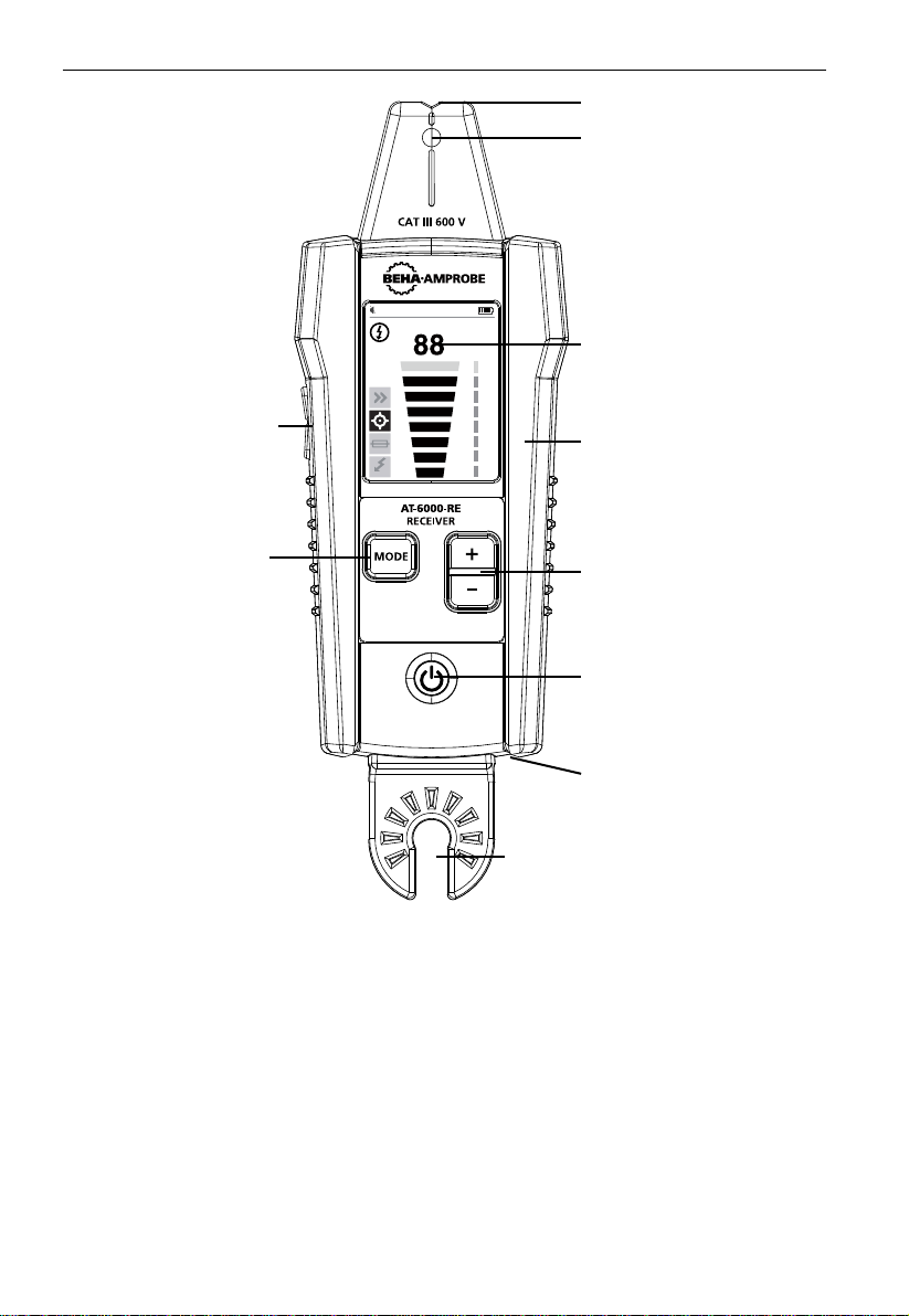
2.1 AT-6000-RE Receiver
The AT-6000-RE Receiver detects the signal in wires and cables using the following methods:
Active (using transmitter)
Uses a signal generated by the AT-6000-TE transmitter to trace either Energized or De-
energized wires.
The main advantage of this method is the ability to trace the path of the particular wire
using a receiver. Since the signal is not present in any neigboring wires, the receiver will
detect only a wire that is connected to the transmitter.
Active tracing method is used when a receiver is set to: Quick Scan or Precision Tracing or
Breaker/Fuse Identification modes.
Passive (without transmitter)
Uses electromagnetic fied sourounding Energized wires.
Trace any energized wire from 90 to 600 V AC using only the the AT-6000-RE receiver by
sensing the wire’s energy field.
The passive method is very easy and convenient to use because it does not require a
transmitter. However, the AT-6000-RE is not selective to a particular wire and will indicate
any energized wire from 90 to 600 V AC.
This method is best for simple tracing applications where the wire is energized and no other
wires are located nearby.
Passive tracing method is used when receiver is set to Non-contact voltage (NCV)detection
mode.
Note: The AT-6000-RE will NOT detect signals from the wire through metal conduit or
shielded cable. Refer to Special Applications, section 4.4 “Tracing Wires In Metal Conduit”
for alternative tracing methods.
2. KIT COMPONENTS
6
2. KIT COMPONENTS
NCV
TIP SENSOR
LC-DISPLAY
Full color TFT display
RUBBER OVERMOLDED
ENCLOSURE
SENSITIVITY ADJUSTMENT
BUTTON (-/+)
VOLUME
ADJUSTMENT
BUTTON (+/-)
FUNCTION/MODE
BUTTON
Toggles between modes:
- Quick Scan mode
- Precision Tracing mode
- Breaker/Fuse mode
- Non-contact-voltage
(NCV) detection
mode, passive tracing
POWER BUTTON
Turns unit On / Off
BATTERY COMPARTMENT
(Back side)
HOT STICK ATTACHMENT POINT
(Do not use for voltage higher
than 600V)
Figure 2.1a: Overview of AT-6000-RE Receiver
ON/OFF: Short press to turn the receiver on. Long press >2s to turn the receiver off.
VOLUME ADJUSTMENT: The volume can be changed by short presses on VOLUME UP/ DOWN
buttons. The mute and four loudness level are available. The chosen volume level will be
shown on the display.
TIP SENSOR LED: This LED is blinking when signal is detected. The stronger the signal, as
faster is the blinking.
FUNCTION/MODE: This button toggles between the different modes:
- Quick Scan mode (tracing energized + de-energized wires)
- Precision Tracing mode (tracing energized + de-energized wires)
- Breaker/Fuse mode (tracing energized + de-energized fuses)
- Non-contact-voltage (NCV) detection mode, passive tracing
SENSETIVITY: This button is to adjust the sensitivity of the receiver. Eight levels are available.
TIP SENSOR LED

7
2. KIT COMPONENTS
NC V
88
Sound volume
Signal strength (0-99)
Battery voltage
Sensitivity level (1-8)
Bargraph - proportional
to signal strength
Energized
Quick Scan mode
Precision Tracing mode
Breaker/Fuse mode
Non-contact voltage (NCV)
detection mode,
passive tracing mode
Figure 2.1b

8
2.2 AT-6000-TE Transmitter
The AT-6000-TE Transmitter works on energized and de-energized circuits up to 600 V AC/DC
in Category I through Category III electrical environments.
Transmitter signal modes:
High Signal (Hi) – Recommended for most wire tracing applications on energized and
de-energized circuits including breaker/fuse location. This function will be used most of the time.
Low Signal (Lo) – The LOW mode function is rarely used, and only for the most demanding
and precise wire tracing applications. It limits the signal level generated by the transmitter
in order to pinpoint the wire location more precisely. A lower signal level reduces coupling
to neighboring wires and metal objects, and helps to avoid misreading due to ghost signals.
A lower signal also helps to prevent oversaturating the AT-6000-RE with a strong signal that
covers too large an area.
Loop mode (initiated by pressing and holding the Hi button for 2 seconds) – use when
working with closed loop de-energized circuits, such as shorted wires, shielded cables or de-
energized wires that are grounded on the far-end.
How is Loop function different from the Hi or Lo settings when using test leads?
Both Hi and Lo modes generate a signal in all open branches of the de-energized circuit.
This is useful when tracing open wires. Hi/Lo modes will NOT work on wires that are
grounded on the far-end because the signal cannot be generated.
Loop mode generates a signal (current flow) in closed loop de-energized circuits only. Loop
mode is used to pinpoint the location of a short (because the current will not be able to
flow in open branches) and to trace wires that are grounded on the far end (because the
loop is closed via ground connection).
Note: Loop mode only works on de-energized circuits. It is automatically disabled when
transmitter is connected to energized line/phase with test leads.
2. KIT COMPONENTS
figure 2.2a figure 2.2b
figure 2.2c figure 2.2d

9
Working with the transmitter:
When the transmitter is on and connected to the circuit with test leads, it checks for voltage.
A red Voltage Warning Indicator will light up if the transmitter detects dangerous voltage
above 30V AC/DC.
IMPORTANT!
The Voltage Warning Indicator light will blink when overvoltage (>650V AC/DC) is detected.
In case of overvoltage immediately disconnect Transmitter from the circuit!
This Voltage Waning Indicator is not desinged to check for absence of voltage. Please use a
voltage tester therefore.
If High (Hi) or Low (Lo) Signal button is pressed momentarily, the transmitter starts
generating a tracing signal. Based on detected voltage, the transmitter automatically
switches to either:
• Energized mode (30 to 600V AC/DC) generating 6kHZ frequency or
• De-energized mode (0 to 30V AC/DC) generating 33kHz frequency
The Energized Mode uses a lower transmission frequency (6kHz) than de-energized mode
(33 kHz) to reduce signal coupling between wires. De-energized mode requires higher
frequency (33 kHz) in order to generate a reliable signal.
Energized mode: In energized mode, the transmitter draws a very low current from the
energized circuit and generates a 6 kHz signal. This is a very important feature of the
AT-6000-TE, since drawing current does not inject any signal that would harm sensitive
equipment connected to the circuit. The signal is also generated in a direct path between
the transmitter and the power source, thus NOT placing a signal onto any branches enabling
wiring tracing directly back to the breaker/fuse panel. Please note that due to this feature,
the transmitter has to be connected on the load side of the circuit.
De-energized mode: In de-energized mode the transmitter injects a 33 kHz signal onto the
circuit. In this mode, since the signal is injected, it will travel through all the circuit branches.
It is a high frequency, very low energy signal that will not harm any sensitive equipment.
2. KIT COMPONENTS
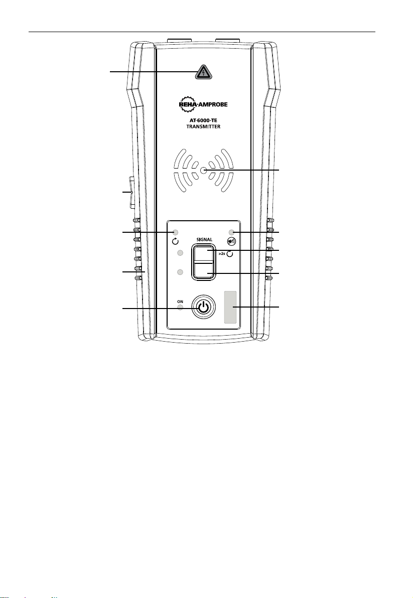
10
HI
LO
VOLTAGE WARNING
INDICATOR
1. Red: Energized
2. OFF: De-energized
3. Blinking: overvoltage
LOW SIGNAL
(PRECISION) MODE
ON / OFF BUTTON
TRANSMISSION MODE
INDICATOR
HIGH SIGNAL MODE
Press >2s for Loop mode
MUTE INDICATOR
BATTERY STATUS
LOOP MODE
INDICATOR
RUBBER OVERMOLDED
ENCLOSURE
VOLUME
ADJUSTMENT
BUTTON (+/-)
Figure 2.2e: Overview of AT-6000-TE Transmitter
ON/OFF: Short press to turn the transmitter on. Long press >2s to turn the transmitter off.
VOLUME ADJUSTMENT BUTTON: The volume can be changed by short presses on VOLUME UP/
DOWN buttons. The mute and four loudness level are available. The chosen volume level will
be shown on LED display for a short time. If sound is muted, the MUTE LED diode will be on.
The sound pattern is different depending on chosen operating mode, ENERGIZED,
DE-ENERGIZED or LOOP.
VOLTAGE WARNING INDICATOR: ON for energized circuits 30-600 V AC/DC. OFF for circuits
0-30 V AC/DC. Blinking if overvoltage >650 V AC/DC is detected.
TRANSMISSION MODE INDICATOR: The LED diodes will blink with different rhythm
depending on chosen operating mode.
Transmitting in HIGH mode – Fast blinking,
Transmitting in LOW mode – Slow blinking,
Transmitting in LOOP mode – Alternating blinking.
2. KIT COMPONENTS

11
HIGH MODE: Short press on HI pushbutton turn on HIGH transmitting mode. Second short
press on HI button turn off transmitting.
LOW MODE: Short press on LO pushbutton turn on LOW transmitting mode. Second short
press on LO button turn off transmitting.
LOOP MODE: Long press >2s on HI pushbutton turn on LOOP mode. Long press on HI button
turn off LOOP mode.
2.3 CT-400-EUR Signal Clamp
(included with AT-6030-EUR / option for AT-6020-EUR)
The clamp accessory is used for applications when there is no access to the bare conductors.
The clamp attachment enables the AT-6000-TE Transmitter to induce a signal through the
insulation into either wires. The clamp works on low impedance closed circuits.
Figure 2.3a: Overview of CT-400-EUR Signal Clamp
2. KIT COMPONENTS
CONNECTORS TO
TRANSMITTER
JAW
TACTILE
BARRIER
JAW
RELEASE
TEST LEAD
12
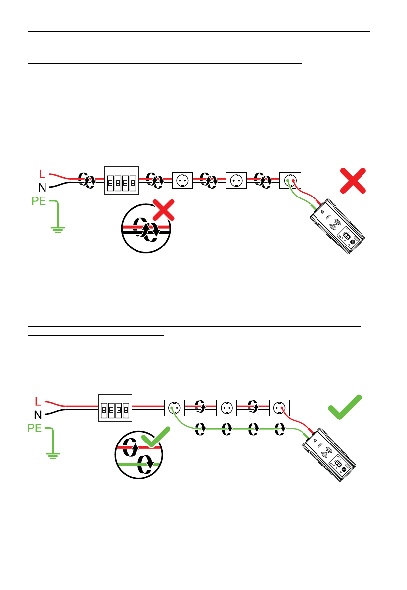
� IMPORTANT NOTICE, PLEASE READ BEFORE YOU START TRACING
Avoiding signal cancellation problems with a separate ground connection
The signal generated by the transmitter creates an electromagnetic field around the wire.
This field is what is detectable by the receiver. The clearer this signal, the easier it is to
trace the wire.
If transmitter is connected to two adjacent wires on the same circuit (for example, line/phase
and neutral wires), the signal travels in one directions through the first wire and then
returns (with opposite direction) through the second one. This causes creation of two
electromagnetic fields around each wire with opposite direction. These opposing fields
will partially or completely cancel each other out, making wire tracing difficult if not
impossible.
Figure 3.0a
To avoid the cancellation effect, a separate neutral or separate ground connection method
should be used. The red test lead of the transmitter should be connected to the line/phase
wire of the circuit you wish to trace, and the green lead to a separate neutral or ground
(such as water pipe, ground stake, metal grounded structure of the building, or outlet
ground connection of an outlet) on a different branch. It is important to understand that
an acceptable separate neutral/ground is NOT the terminal of any receptacle on the same
branch as the wire you wish to trace. If line/phase wire is energized and the transmitter is
properly connected to a separate neutral/ground, the red LED on a transmitter will light up.
The separate neutral/ground connection create the maximum signal strength, because the
electromagnetic field created around the line/phase wire is not being cancelled by a signal
on the return path flowing along an adjacent wire (ground or neutral) in the opposite
direction, but rather through the separate connection.
3. MAIN APPLICATIONS
Figure 3.0b
13
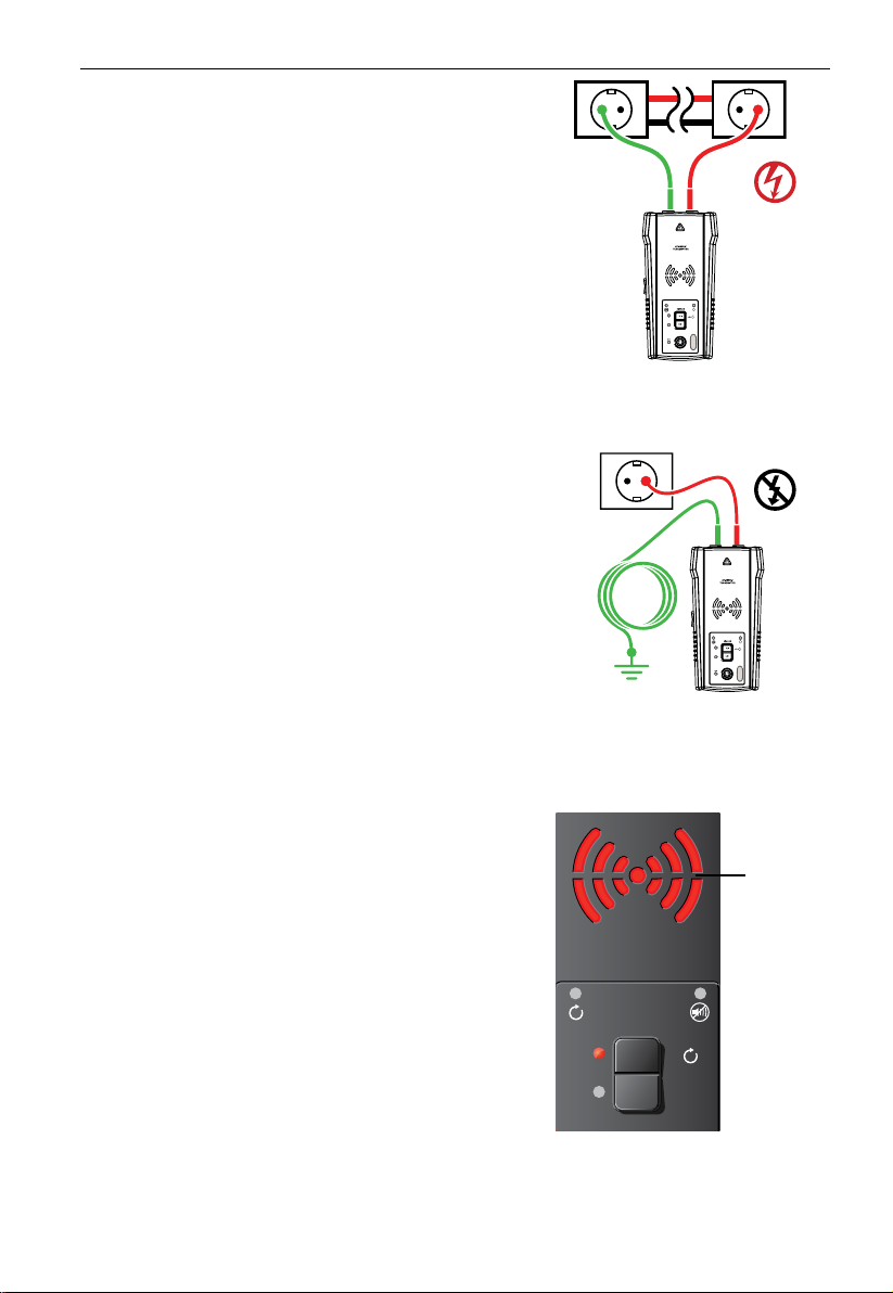
3.1 Tracing – Energized and De-energized Wires
Connecting transmitter test leads
1. Connect green and red test leads to the
transmitter (polarity does not matter).
2. Connect red lead to line/phase wire (on the
load side of the system). The signal will ONLY be
transmitted between the load-side to which the
transmitter is connected and the source of power
(see figure 3.1a).
3. Connect green lead to a separate neutral wire at
the RCD or at a connection point as close to the
RCD as it is possible.*
4. If tracing energized wires, please check if the
voltage warning indicator is ON. Otherwise the
connection you have done is from line/phase to
line/phase or from neutral to neutral or circuit is
de-engergized. In this case redo the connection in
the proper way.
*Note: Please make sure that line/phase wire and
separate neutral are connected to the same RCD,
otherwise the RCD will trip.
For de-energized circuits insted of using neutral
wire it is possible to connect green lead to a
separate ground (metal building structure, metal
water pipe, or ground wire / Protective Ground
(PE)) on a separate circuit.
ATTENTION: Due to safety reasons this is only
allowed in de-energized circuits. (see figure 3.1b)
Do not use a ground wire that runs in parallel to
the wire you are going to trace, as it will reduce or
cancel tracing signal.
NOTE:If circuit is energized you will trip RCD.
Set up the AT-6000-TE Transmitter:
1. Press ON/OFF key to turn on the transmitter.
2. Verify that the test leads are properly connected;
the red LED voltage status light should be on for
energized circuits (with voltage above 30V AC/
DC), and it should be off for de-energized circuits.
Note: Make sure to use the separate neutral/
ground connection as described above!
3. Select HIGH signal mode for most applications.
Screen will appear as shown in figure 3.1c. The
LED display will quickly begin to blink.
Note: The LOW signal precision mode can be
used to limit the signal level generated by the
transmitter in order to more precisely pinpoint wire
location. A lower signal level reduces coupling to
neighboring wires and metal objects and helps to
avoid misreading due to ghost signals. A lower signal
also helps to prevent oversaturating the AT-6000-RE
with a strong signal that covers too large an large
area. The LOW mode function is rarely used, only
for the most demanding and precise wire tracing
applications.
3. MAIN APPLICATIONS - TRACING ENERGIZED AND DE-ENERGIZED WIRES
Figure 3.1a
Proper connection to
line/phase and neutral
Figure 3.1b
Proper connection with
separate ground
AT-6000-T
TRANSMITTER
ON
HI
LO
SIGNAL
>2s
BLINKING
Figure 3.1c:
Transmitter screen showing signal
in HIGH mode

14
Using AT-6000-RE Receiver in Quick Scan Mode
Quick Scan mode detects wires at the longer distance (between a wire and the AT-6000-RE)
but with less precision than Precision Tracing or Breaker/Fuse modes. This feature is used to
verify that the tracing signal is present and to quickly follow the path of the wire. Switch to
Precision Tracing mode to precisely pinpoint the wire, or to Breaker/Fuse mode to locate a
Breaker/Fuse.
1. Press ‘ON/OFF’ push button to turn on the AT-6000-RE. It starts in Quick Scan mode
after turning ON (default mode).
2. Scan a target area with Tip Sensor to find a signal, then you may begin tracing the
detected wire. Increase or decrease sensitivity of the AT-6000-RE by pressing + or - on
the keypad as necessary.
3. For best results while tracing energized wires, align groove on tip sensor with wire
direction as shown (see figure 3.1f/g). Signal may be not detected if not properly
aligned. To verify wire direction, periodically rotate AT-6000-RE 90 degrees. Signal
strength will be the highest when wire is aligned with Tip Sensor groove.
Depending on the detected signal, the AT-6000-RE automatically switches to either
Energized or De-energized mode, and displays this information on the LCD. No
manual setup is necessary.
NC V
Figure 3.1d:
Signal not detected
Figure 3.1e:
Signal detected
NC V
Note: For best results, keep AT-6000-RE at least 1 meter away from the transmitter and its
test leads to minimize signal interference via air and improve wire tracing results.
3. MAIN APPLICATIONS - TRACING ENERGIZED AND DE-ENERGIZED WIRES

15
Using AT-6000-RE Receiver in Precision Tracing Mode
Use Precision Tracing mode to precisely pinpoint the wire location or the place of the fault.
The AT-6000-RE will indicate detected signal strength using two digits’ readout, a bar graph
and a sound.
1. Continue pressing MODE button until the Precision Tracing function is selected.
2. Scan target area with Tip Sensor to find highest signal level. While tracing, periodically
adjust sensitivity to keep signal strength near 50. Increase or decrease sensitivity
by pressing + or - on the keypad. If signal is too strong for precise locating, change
transmitter to LOW mode.
3. For best results while tracing energized wires, align groove on tip sensor with wire
direction as shown (see figure 3.1f/g). Signal may be not detected if not properly
aligned. To verify wire direction, periodically rotate AT-6000-RE 90 degrees. Signal
strength will be the highest when wire is aligned with Tip Sensor groove.
Depending on the detected signal, the AT-6000-RE automatically switches to either
Energized or De-energized mode, and displays this information on the LCD. No
manual setup is necessary.
Align
Tip
groove
Note: For best results, keep the AT-6000-RE at least 1 meter from the transmitter and its test
leads to minimize signal interference and improve wire tracing results.
3. MAIN APPLICATIONS - TRACING ENERGIZED AND DE-ENERGIZED WIRES
Figure 3.1f
Figure 3.1h
Figure 3.1g

16
Breaker/Fuse mode automatically adjusts sensitivity of the AT-6000-RE. As a result, the AT-
6000-RE will pinpoint and indicate just one correct Breaker/Fuse. This enhancement helps to
remove signal strength analysis from the breaker identification process that is typical for less
advanced wire tracers.
3.2 Identifying Breakers and Fuses (Energized and de-energized)
Note: For Breaker/Fuse locating, a simplified direct connection to line/phase and neutral
wires can be used because these wires are separated at the breaker/fuse panel. There
is no risk of signal cancellation effect if wires are at least a few centimeters away from
each other in the area where the breaker/fuse is located. However the separate ground
connection as shown in Wire Tracing modes should be used for superior results specifically
if wires need to be traced in addition to breaker identification.
The simplified direct connection to line/phase and neutral wire will NOT trip the RCD protection.
Figure 3.2a
Connecting transmitter test leads:
1. Use red and green test leads either with probe tips or alligator clips.
2. Plug test leads into Transmitter. Polarity is not important.
3. Connect red and green test leads to line/phase and neutral wires of the same receptacle
or cable (see figure 3.2a).
4. If tracing energized breakers/fuses, please check if the voltage warning indicator is ON.
Otherwise the connection you have done is wrong or circuit is de-engergized. In this
case redo the connection in the proper way.
Set up the AT-6000-TE Transmitter:
1. Press ON/OFF key to turn on the transmitter.
2. Verify that the test leads are properly connected - the red LED voltage status light
should on for circuits with voltage above 30V AC/DC, and it should be off for de-
energized circuits.
3. Select HIGH signal mode for breaker/fuse tracing.
3. MAIN APPLICATIONS – LOCATING BREAKERS/FUSES
Other manuals for AT-6000-EUR Series
1
This manual suits for next models
2
Table of contents
Languages:
Other Beha-Amprobe GPS manuals


