manuals.online logo
Brands
  1. Home
  2. •
  3. Brands
  4. •
  5. Behringer
  6. •
  7. Amplifier
  8. •
  9. Behringer AUTOCOM PRO-XL MDX1600 User manual

Behringer AUTOCOM PRO-XL MDX1600 User manual

Users manual
Version 1.0 November 2002
DEUTSCH
POWERPLAY PRO-XL HA4700/POWERPLAY PRO-8 HA8000
POWERPLAY PRO-XL HA4700
POWERPLAY PRO-8 HA8000
www.behringer.com
ENGLISH
POWERPLAY PRO-XL HA4700/PRO-8 HA8000
2
DETAILED SAFETY INSTRUCTIONS:
All the safety and operation instructions should be read before
the device is operated.
Retain Instructions:
The safety and operating instructions should be retained for
future reference.
Heed Warnings:
All warnings on the device and in the operating instructions
should be adhered to.
Follo instructions:
All operation and user instructions should be followed.
Water and Moisture:
The device should not be used near water (e.g. near a bathtub,
washbowl, kitchen sink, laundry tub, in a wet basement, near a
swimming pool etc.).
Ventilation:
The device should be situated so that its location or position
does not interfere with its proper ventilation. For example, the
device should not be placed on a bed, sofa, rug, or similar surface
that may block the ventilation openings, or used in a built in
installation, such as a bookcase or cabinet that may impede the
flow of air through the ventilation openings.
Heat:
The device should be situated away from heat sources such as
radiators, heat registers, stoves, or other devices (including
amplifiers) that produce heat.
Po er Source:
The device should only be connected to a power supply of the
type described in the operating instructions or on the device.
Grounding or Polarization:
This device must be grounded.
Po er Cords:
Power cords should be routed so that they are not likely to be
walked on or pinched by items placed upon or against them, paying
particular attention to cords and plugs, sockets, outlets and the
point where they exit from the device.
Cleaning:
The device should be cleaned only as recommended by the
manufacturer.
Non-use Periods:
The power cord of the device should be unplugged from the
outlet when left unused for a long period of time.
Debris and Liquid Entry:
Debris and/or liquids should be kept from entering the enclosure
through openings.
Damage Requiring Service:
The device should be serviced by qualified service personnel
when:
sThe power cord or the plug has been damaged; or
sDebris or liquid has entered the device; or
sThe device has been exposed to rain; or
sThe device does not appear to operate normally or exhibits a
marked change in performance; or
sThe device has been dropped, or the enclosure damaged.
Servicing:
The user should not attempt to service the device beyond that
which is described in the operating instructions. All other servicing
should be referred to qualified service personnel.
This symbol, wherever it appears, alerts you to the
presence of uninsulated dangerous voltage inside
the enclosurevoltage that may be sufficient to
constitute a risk of shock.
This symbol, wherever it appears, alerts you to
important operating and maintenance instructions
in the accompanying literature. Please read the
manual.
CAUTION: To reduce the risk of electric shock, do not remove
the cover (or back). No user serviceable parts inside;
refer servicing to qualified personnel.
WARNING: To reduce the risk of fire or electric shock, do not
expose this device to rain and moisture.
SAFETY PRECAUTIONS
POWERPLAY PRO-XL HA4700/PRO-8 HA8000
3
FOREWORD
Dear Customer,
welcome to the team of
BEHRINGER users, and
thank you very much for
expressing your confi
dence in us by purchasing
the POWERPLAY PRO.
Writing this foreword for
you gives me great
pleasure, because it re
presents the culmination
of many months of hard
work delivered by our
engineering team to
achieve a very ambitious
goal: to present two out
standing pieces of
equipment, whose flexi
bility lets them find use
in both studios and
P.A. situations.
The task of designing our new POWERPLAY PRO certainly meant
a great deal of responsibility, which we assumed by focusing on
you, the discerning user and musician. Meeting your expectations
also meant a lot of work and night shifts. But it was fun, too.
Developing a product usually brings a lot of people together, and
what a great feeling it is when all who participated in such a project
can be proud of what theyve achieved.
It is our philosophy to share our enjoyment with you, because
you are the most important member of the BEHRINGER team.
With your highly competent suggestions for new products youve
made a significant contribution to shaping our company and
making it successful. In return, we guarantee you uncompromising
quality (manufactured under ISO9000 certified management
system) as well as excellent technical and audio properties at an
extremely reasonable price. All of this will enable you to give
free rein to your creativity without being hampered by budget
constraints.
We are often asked how we manage to produce such high
quality devices at such unbelievably low prices. The answer is
quite simple: its you, our customers! Many satisfied customers
mean large sales volumes enabling us to get better purchasing
terms for components, etc. Isnt it only fair to pass this benefit on
to you? Because we know that your success is our success too!
I would like to thank all of you who have made the
POWERPLAY PRO possible. You have all made your own
personal contributions, from the developers to the many other
employees at this company, and to you, the BEHRINGER user.
My friends, its been worth the effort!
Thank you very much,
Uli Behringer
1. INTRODUCTION
Congratulations! With the BEHRINGER POWERPLAY PRO,
you have acquired a high end headphone amplifier. Both
POWERPLAY PRO units were developed with the most de
manding applications in mind: professional recording, radio and
television studios, as well as CD/digital sound production. They
were developed as benchmark units for judging mixdown quality
as well as distribution amplifiers for flexible playback appli
cations in studio environments.
Balanced inputs and outputs
Both BEHRINGER POWERPLAY PROs feature electronically
servo balanced inputs and outputs. The servo function auto
matically recognizes when unbalanced pins are assigned. It
internally modifies the nominal signal level, thus preventing any
occurence of signal level difference between inputs and outputs
(6 dB correction).
+The follo ing users manual is intended to familiarize
you ith the units control elements, so that you can
master all the functions. After having thoroughly read
the users manual, store it at a safe place for future
reference.
1.1 Before you get started
The POWERPLAY PRO was carefully packed at the assembly
plant to assure secure transport. Should the condition of the
cardboard box suggest that damage may have taken place, please
inspect the unit immediately and look for physical indications of
damage.
+Damaged units should NEVER be sent directly to us.
Please inform the dealer from hom you acquired the
unit immediately as ell as the transportation company
from hich you took delivery of the unit. Other ise, all
claims for replacement/repair may be rendered invalid.
1. INTRODUCTION
TABLE OF CONTENTS
1. INTRODUCTION ........................................................ 3
1.1 Before you get started .................................................... 3
1.1.1 Initial operation ..................................................... 3
1.1.2 Warranty ............................................................... 4
1.2 The users manual .......................................................... 4
2. CONTROL ELEMENTS ............................................. 4
2.1 Front panel ...................................................................... 4
2.2 Rear panel ...................................................................... 5
3. APPLICATION GUIDELINES .................................... 5
3.1 Using the MAIN IN connectors ....................................... 5
3.2 AUX IN inputs (HA4700 only) ......................................... 5
3.3 Using the DIRECT IN connector .................................... 6
3.4 Mono mode ..................................................................... 6
3.5 MUTE function (HA4700 only) ........................................ 6
3.6 Connecting multiple headphones ................................... 6
4. AUDIO CONNECTIONS ............................................ 6
5. SPECIFICATIONS ..................................................... 7
6. WARRANTY .............................................................. 9
POWERPLAY PRO-XL HA4700/PRO-8 HA8000
4
1.1.1 Initi l oper tion
Please make sure the unit is provided with sufficient ventilation,
and never place the POWERPLAY PRO on top of an amplifier or
in the vicinity of a heater to avoid the risk of overheating.
+Before plugging the unit into a po er socket, please
make sure you have selected the correct voltage:
The fuse compartment near the power plug socket contains
three triangular markings. Two of these triangles are opposite
one another. The voltage indicated adjacent to these markings is
the voltage to which your unit has been set up, and can be altered
by rotating the fuse compartment by 180°. ATTENTION: This
does not apply to export models that ere for example
manufactured only for use ith 120 V!
+If you alter the units voltage, you must change the fuses
accordingly. The correct value of the fuses needed can
be found in the chapter TECHNICAL DATA.
+Faulty fuses must be replaced ith fuses of appropriate
rating ithout exception! The correct value of the fuses
needed can be found in the chapter TECHNICAL DATA.
Power is delivered via the cable enclosed with the unit. All
requiered safety precautions have been adhered to.
+Please make sure that the unit is grounded at all times.
For your o n protection, you should never tamper ith
the grounding of the cable or the unit itself.
1.1.2 W rr nty
Please take a few minutes and send us the completely filled
out warranty card within 14 days of the date of purchase. You
may also register online at www.behringer.com. The serial number
needed for the registration is located at the top of the unit. Failure
to register your product may void future warranty claims.
1.2 The users manual
This users manual has been written in such a way to enable
you an overview over the control elements of the unit and offers
at the same time detailed information about possible applications.
To facilitate quick look ups, control elements have been described
in groups depending on their function. Should you need detailed
information about specific topics not covered in this manual,
please visit our website at www.behringer.com. For example,
additional information about power amps and effects processors
is found there.
ATTENTION!
+We ould like to bring your attention to the fact that
extremely loud sound levels may damage your hearing
as ell as your headphones. Please lo er all OUTPUT
LEVEL knobs left ards before po ering up the unit.
2. CONTROL ELEMENTS
This chapter contains descriptions of various control elements
of your POWERPLAY PRO. All controls and connections are
discussed in detail. Additionally, useful advice about their possible
applications is also given.
The HA8000 has eight independent amplifiers for connecting
headphones, while the HA4700 has four. The latter has several
additional features not found in the HA8000 due to space
considerations. The differences between the two units are
explained in detail in the text sections that follow.
2.1 Front panel
Fig. 2.1: Input section
The DIRECT IN socket is used to feed in additional stereo
signals. In the case of the HA4700, the signal brought in via
the DIRECT IN input has the same priority as the MAIN
signal. The HA8000 has a separate DIRECT INPUT
connector for each channel (see fig. 2.3). In the case
of this model, the MAIN signal being fed in is automatically
interrupted when the said input is in use.
The MASTER LEVEL control governs the level of the input
signal that is fed through the MAIN INPUT connectors on
the back or through the DIRECT IN connector.
The HA8000 features two level controls (MAIN IN 1/
MAIN IN 2), so that two separately controllable input signals
can be connected. You select which of the two signals is
monitored by using the IN 1/IN 2 switches in the
respective channel sections.
The 4 digit INPUT LEVEL display informs you about the
input level signal and diplays it in the range between 30
and 0 dB. When the unit is powered on, the N LED lights
up. You achive the best input signal quality when its level is
at the highest level just before it starts distorting. The clip
LED should light up only during the highest signal peaks.
Fig. 2.2: Individual headphones amplifier sections
The 8 digit UTPUT LEVEL display informs you about the
ouput signal level of each individual channel, and diplays it
in the range between 30 and 0 dB. When the clip LED
lights up, lower the amount of gain applied to the individual
channels to avoid distortion.
The BASS control (HA4700 only) attenuates or boosts the
low frequency portions of the signal (+/ 12 dB).
2. CONTROL ELE ENTS
POWERPLAY PRO-XL HA4700/PRO-8 HA8000
5
The TREBLE control (HA4700 only) attenuates or boosts
the high frequency portion of the signal (+/ 12 dB).
The L MUTE and R MUTE switches allow you to mute the
respective input signal, so that only the remaining input
signal is audible (HA4700 only).
The PH NES UT connector is connected in parallel to
the output connectors located on the rear, presenting
an easily accessible additional monitor option for individual
channels. This function is particularly helpful when the unit
is permanently installed in a rack.
The AUX IN input is used to mix an additional input signal
into the MAIN IN or DIRECT IN connectors (HA4700 only).
Should you want to use this option on a mono signal, we
recommend using the ST./2 CH. switch (position 2 CH,
depressed) in order to hear the signal in both ears.
The ST./2-CH. switch is used to alternate whether input
signals are audible in stereo (not depressed: ST.) or in mono
(depressed: 2 CH.) The HA8000 features a MONO switch
instead of a ST./2 CH. switch .
The BALANCE control (HA4700 only) regulates the stereo
image of input signals, provided that the AUX IN input of
one of the amp sections is not already in use. When the
AUX IN section already has a signal assigned to it, the
BALANCE control governs the ratio between MAIN IN
(DIRECT IN) and AUX IN signal.
The HA8000 does not feature a BALANCE control.
Headphones volume of the individual amp sections is
regulated using the UTPUT LEVEL control. Both the left
and the right channel are regulated simultaneously.
The P WER switch powers the POWERPLAYPRO on. You
should always make sure that the POWER switch is in the
Off position when initially connecting the unit to the mains.
+Please take note: Merely s itching the unit off does not
mean that it is fully disconnected from the mains. When
not using the unit for prolonged periods of time, please
unplug the units po er cord from the po er outlet.
The MAIN IN 1 or MAIN IN 2 input signal is selected by
using the IN 1/IN 2 switch. When the DIRECT INPUT of the
channel has a signal assigned to it, you can hear the said
signal only (HA8000 only).
When you depress the M N switch (HA8000 only), the
signal is played in mono. Singers in particular appreciate
this function because a mono signal is much less distracting
to listen to than a comparable stereo signal. A mono signal
makes spacial orientation during live performances easier.
2.2 Rear panel
Power is supplied via an IEC connector. The matching cable
is provided with the unit.
FUSE C MPARTMENT / V LTAGE SELECTI N. Before
connecting the unit to a power outlet, please make sure
that the selected voltage matches your local voltage. When
replacing fuses, please make sure that you always use fuses
of the same type. Some units allow for switching between
230 V und 120 V. Please note: when connecting a unit
intended for the European market to a 120 V power outlet,
you must also replace the factory fuse with a higher value
fuse.
The HEADPH NE UT connectors of the individual amp
sections are also used for connecting headphones
(HA8000: PH NES UTPUT). The HA4700 features two
additional headphones connectors per channel located
on the rear; the HA8000 has one.
Fig. 2.3: Mains supply, fuses compartment and
headphone outputs
Various input signals can be connected to the HA8000 by
utilizing a separate DIRECT IN connection for each amp
section, located on the rear. If a signal is fed into this
connector, both MAIN IN signals will be muted.
These are the MAIN UT connectors of the HA4700. The
respective jacks and XLR connectors are wired in parallel.
Via these connectors, you can link as many headphone
amps as desired to allow for connection of additional
headphones. The HA8000 has no MAIN OUT connectors.
To connect additional units on a per need basis, you can
use HA8000s PHONES OUTPUT connectors.
Fig. 2.4: MAIN IN and MAIN UT connectors
The MAIN IN connectors of the HA4700 come as balanced
1/4" TRS and XLR connectors.
The HA8000 features only 1/4" TRS connectors for MAIN
INPUT 1 and MAIN INPUT 2.
3. APPLICATION GUIDELINES
3.1 Using the MAI I connectors
Connect a program source with the MAIN IN connectors located
on the rear, and connect your headphones to an amp section of
your choice. Set the MASTER LEVEL and BALANCE controls
(HA4700) in the center position. The MASTER LEVEL control is
used to lower or raise the volume level of all headphones which
receive signals via the MAIN IN inputs and/or the DIRECT IN
input. In the case of the HA8000, MAIN IN controls 1 and 2
regulate the input level of two separate input signals. The indi
vidual OUTPUT LEVEL controls are used for adjusting the desired
channel volume only.
3.2 AUX I inputs (HA4700 only)
As a general rule, the AUX IN inputs are used to add an extra
input signal to the main signal, whereby the respective BALANCE
control regulates the relative ratio of those signals to one another.
3. APPLICATION GUIDELINES
POWERPLAY PRO-XL HA4700/PRO-8 HA8000
6
This way, you can for example effortlessly record vocals and
feed in an already existing playback using your POWERPLAY
PRO XL HA4700. The playback signal is fed through the MAIN IN
inputs, and the preamplified vocal signal is fed into the AUX IN
connector. The respective BALANCE control should be set up in
such a way that the singer gets a perfectly matched mix between
the playback and the vocals, whereby the OUTPUT LEVEL control
regulates the overall volume.
Fig. 3.1: Playback application in a studio
In addition to the usage of all channels via the MAIN input,
each of the four amplifiers can also be used fully independently.
To this end, you may also use the AUX IN inputs in conjunction
with the BALANCE controls. When the BALANCE control is turned
to the left (AUX position), the MAIN signal is faded out, and the
AUX IN signals are fed into their respective amplifiers. Using
individual amplifiers separately lets you provide individual mixes
to up to four musicians.
Fig. 3.2: Monitor live application
3.3 Using the DIRECT I connector
The DIRECT IN connector (HA4700) is located on the left side of
the front section. For example, you can use this connector to provide
musicians with the signal of a DAT recorder or CD player. The
HA8000 has a separate DIRECT IN connector for each amplifier
(located on the rear). In the case of the HA8000, allocating a signal
to this connector mutes the MAIN IN signal. The input level must
be externally set in this case. This way, you can use each amplifier
section for a separate headphone signal.
3.4 Mono mode
Stereo signals can often have an irritating effect in certain
monitoring applications, especially when performing live. These
negative effects are particularly apparent when both channels
show great channel separation, i.e. a different information content
coupled with varying volume levels. The ST./2 CH. switch
(HA8000: the MONO switch) allows coupling the left and the right
channels into a single mono signal, withouth needing a
Y adapter or a special cable.
3.5 MUTE function (HA4700 only)
When the ST./2 CH. switch is depressed, the unit is running mono.
By depressing either one of the MUTE switches, the respective inputs
signal (i.e. either the left or the right input) is muted, while the signal
not being muted can be heard on BOTH (left and right) headphone
outputs. This allows you to feed two different program sources yet
be able to listen to only one of them on a per need basis.
3.6 Connecting multiple headphones
The HA4700 features three headphones connectors altogether,
while the HA8000 has two. You can connect multiple headphones
to an amp simultaneously, provided that the minimal output load
impedance of the amp does not fall below 8 Ohms. In the case of
the HA8000, the minimal output load impedance is 100 Ohms per
amp.
+When connecting t o headphones, individual
headphones should not have impedance lo er than
16 Ohms; hen connecting three headphones,
individual headphones should not have impedance
lo er than 24 Ohms (HA4700). When connecting t o
headphones to the HA8000, the impedance of individual
headphones should not fall belo 200 Ohms.
Even though going under the above mentioned minimal impe
dances does not cause deffective operation, you may experience
a quality loss audible as lowered performance and distortion.
4. AUDIO CONNECTIONS
Fig. 4.1: XLR connector
Fig. 4.2: 1/4" TS connector
Fig. 4.3: 1/4" TRS connector
4. AUDIO CONNECTIONS
POWERPLAY PRO-XL HA4700/PRO-8 HA8000
7
Fig. 4.4: 1/4" TRS connector for headphones operation
+Please assure that the unit is installed and operated
only by people ith an understanding of the units
functions. During and after the installation al ays make
sure that those handling the unit are themselves
properly grounded. Failure to do so may cause
undesirable or faulty operation through electrostatic
discharge.
5. SPECIFICATIONS
5. SPECIFICATIONS
32:(53/$<352;/+$ 32:(53/$<352+$
$8',2,13876
MAIN IN HF-filtered, servo-balanced XLR- and
1/4" TRS connectors
HF-filtered, servo-balanced 1/4" TRS
connectors
Input impedance 40 kΩbalanced,
30 kΩunbalanced
40 kΩbalanced,
20 kΩunbalanced
Max. input level
CMRR
AUX IN 1/4" TRS connector (stereo) -
Input impedance 5 kΩ-
Max. input level +22 dBu -
DIRECT IN
Input impedance
$8',22873876
MAIN OUT XLR- and 1/4" TRS connectors, balanced -
PHONES OUTPUT
32:(5$03/,),(5
Max. output power +24 dBm (load impedance 100 Ω)
+21 dBm (load impedance 8 Ω) +24 dBm (load impedance 100 Ω)
Min. output load impedance 8 Ω100 Ω
6<67(063(&,),&$7,216
Frequency response
Noise
Dynamic range
Distortion (THD)
10 Hz to 150 kHz, +/-3 dB
22 Hz to 22 kHz >90 dB @ 0 dBu
22 Hz to 22 kHz: 110 dB
0.006 % typ. @ +4 dBu,
1 kHz, Gain 1
16 dBu balanced and unbalanced
typically 40 dB, >55 dB @ 1 kHz
1/4" TRS connector (stereo)
15 kΩ
(continued on next page)
POWERPLAY PRO-XL HA4700/PRO-8 HA8000
8
32:(53/$<352;/+$ 32:(53/$<352+$
)81&7,21&21752/6
Input Level
Balance per channel mix between Aux and Main signals /
balance between right and left channel -
Output Level per channel
Treble cutoff frequency: 6 kHz;
range +/- 12 dB -
Bass cutoff frequency: 200 Hz,
range +/- 12 dB -
)81&7,216:,7&+(6
Stereo/2-Channel switches between stereo mode and
2-channel mode -
Main In 1/Main In 2 - switches between MAIN Input 1 and
MAIN Input 2
Left Mute mutes the left signal of the respective
channel -
Right Mute mutes the right signal of the respective
channel -
Mono - switches this section to mono
',63/$<6
Input Level
Output Level
32:(56833/<
Power consuption 34 W 30 W
Mains connection
',0(16,216$1':(,*+7
approx. 2.3 kg approx. 2.35 kg
approx. 5.08 lbs approx. 5.19 lbs
100 - 120 V~:
7P$+
200 - 240 V~:
7P$+
variable
Japan 100 V~, 50 - 60 Hz
General export model 120/230 V~, 50 - 60 Hz
variable
approx. 44.5 mm x 482.6 mm x 217 mm
approx. 1 ¾" x 19" x 8 ½"
Europe/U.K./Australia 230 V~, 50 Hz
4-digit LED-display: -30/-12/0 dB/CLIP
8-digit LED-display: -30/-24/-18/-12/-6/-3/0 dB/CLIP
USA/Canada 120 V~, 60 Hz
Standard IEC receptacle
Mains voltage
Weight
Dimensions (H x W x D)
Fuses
BEHRINGER continuously strives to assure the highest quality standards possible. Required modifications may be implemented without prior notice.
echnical data and the appearance of the unit may deviate from the above values and/or illustrations.
5. SPECIFICATIONS
POWERPLAY PRO-XL HA4700/PRO-8 HA8000
96. WARRANTY
6. WARRANTY
§ 1 WARRANTY CARD/ONLINE REGISTRATION
To be protected by the extended warranty, the buyer must
complete and return the enclosed warranty card within 14 days
of the date of purchase to BEHRINGER Spezielle Studiotechnik
GmbH, in accordance with the conditions stipulated in § 3. Failure
to return the card in due time (date as per postmark) will void any
extended warranty claims. Based on the conditions herein, the
buyer may also choose to use the online registration option via
the Internet (www.behringer.com or www.behringer.de).
§ 2 WARRANTY
1. BEHRINGER (BEHRINGER Spezielle Studiotechnik GmbH
including all BEHRINGER subsidiaries listed on the enclosed
page, except BEHRINGER Japan) warrants the mechanical and
electronic components of this product to be free of defects in
material and workmanship for a period of one (1) year* from the
original date of purchase, in accordance with the warranty
regulations described below. If the product shows any defects
within the specified warranty period that are not excluded from
this warranty as described under § 3 and 4, BEHRINGER shall,
at its discretion, either replace or repair the product using suitable
new or reconditioned parts. In the case that other parts are used
which constitute an improvement, BEHRINGER may, at its
discretion, charge the customer for the additional cost of these
parts.
2. If the warranty claim proves to be justified, the product will
be returned to the user freight prepaid.
3. Warranty claims other than those indicated above are
expressly excluded.
§ 3 RETURN AUTHORIZATION NUMBER
1. To obtain warranty service, the buyer (or his authorized dealer)
must call BEHRINGER (see enclosed list) during normal business
hours BEFORE returning the product. All inquiries must be
accompanied by a description of the problem. BEHRINGER will
then issue a return authorization number.
2. Subsequently, the product must be returned in its original
shipping carton, together with the return authorization number to
the address indicated by BEHRINGER.
3. Shipments without freight prepaid will not be accepted.
§ 4 WARRANTY REGULATIONS
1. Warranty services will be furnished only if the product is
accompanied by a copy of the original retail dealers invoice. Any
product deemed eligible for repair or replacement by BEHRINGER
under the terms of this warranty will be repaired or replaced within
30 days of receipt of the product at BEHRINGER.
2. If the product needs to be modified or adapted in order to
comply with applicable technical or safety standards on a national
or local level, in any country which is not the country for which the
product was originally developed and manufactured, this
modification/adaptation shall not be considered a defect in
materials or workmanship. The warranty does not cover any such
modification/adaptation, irrespective of whether it was carried out
properly or not. Under the terms of this warranty, BEHRINGER
shall not be held responsible for any cost resulting from such a
modification/adaptation.
3. Free inspections and maintenance/repair work are expressly
excluded from this warranty, in particular, if caused by improper
handling of the product by the user. This also applies to defects
caused by normal wear and tear, in particular, of faders,
potentiometers, keys/buttons and similar parts.
4. Damages/defects caused by the following conditions are not
covered by this warranty:
simproper handling, neglect or failure to operate the unit in
compliance with the instructions given in BEHRINGER user
or service manuals.
sconnection or operation of the unit in any way that does not
comply with the technical or safety regulations applicable in
the country where the product is used.
sdamages/defects caused by force majeure or any other
condition that is beyond the control of BEHRINGER.
5. Any repair or opening of the unit carried out by unauthorized
personnel (user included) will void the warranty.
6. If an inspection of the product by BEHRINGER shows that
the defect in question is not covered by the warranty, the inspection
costs are payable by the customer.
7. Products which do not meet the terms of this warranty will be
repaired exclusively at the buyers expense. BEHRINGER will
inform the buyer of any such circumstance. If the buyer fails to
submit a written repair order within 6 weeks after notification,
BEHRINGER will return the unit C.O.D. with a separate invoice
for freight and packing. Such costs will also be invoiced separately
when the buyer has sent in a written repair order.
§ 5 WARRANTY TRANSFERABILITY
This warranty is extended exclusively to the original buyer
(customer of retail dealer) and is not transferable to anyone who
may subsequently purchase this product. No other person (retail
dealer, etc.) shall be entitled to give any warranty promise on
behalf of BEHRINGER.
§ 6 CLAIM FOR DAMAGES
Failure of BEHRINGER to provide proper warranty service shall
not entitle the buyer to claim (consequential) damages. In no
event shall the liability of BEHRINGER exceed the invoiced value
of the product.
§ 7 OTHER WARRANTY RIGHTS AND NATIONAL LAW
1. This warranty does not exclude or limit the buyers statutory
rights provided by national law, in particular, any such rights
against the seller that arise from a legally effective purchase
contract.
2. The warranty regulations mentioned herein are applicable
unless they constitute an infringement of national warranty law.
* Customers in the European Union please contact
BEHRINGER Germany Support for further details.
The information contained in this manual is subject to change without notice. No part of this manual may be reproduced or
transmitted in any form or by any means, electronic or mechanical, including photocopying and recording of any kind, for any
purpose, without the express written permission of BEHRINGER Spezielle Studiotechnik GmbH.
BEHRINGER and POWERPLAY are registered trademarks. ALL RIGHTS RESERVED.
© 2002 BEHRINGER Spezielle Studiotechnik GmbH.
BEHRINGER Spezielle Studiotechnik GmbH, Hanns Martin Schleyer Str. 36 38, 47877 Willich Münchheide II, Germany
Tel. +49 (0) 21 54 / 92 06 0, Fax +49 (0) 21 54 / 92 06 30

Other manuals for AUTOCOM PRO-XL MDX1600

4

This manual suits for next models

5

Other Behringer Amplifier manuals

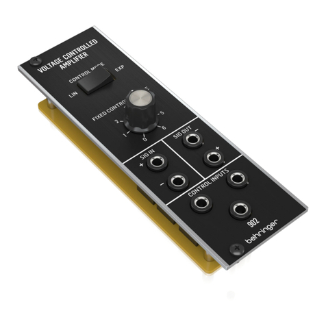
Behringer 902 User manual

Behringer

Behringer 902 User manual

Behringer V-Tone GMX210 User manual

Behringer

Behringer V-Tone GMX210 User manual

Behringer Ultratone K900FX User manual

Behringer

Behringer Ultratone K900FX User manual

Behringer Thunderbird BX108 User manual

Behringer

Behringer Thunderbird BX108 User manual

Behringer Ultrafex Car EX100 User manual

Behringer

Behringer Ultrafex Car EX100 User manual

Behringer Bass V-Amp User manual

Behringer

Behringer Bass V-Amp User manual

Behringer Powerplay Pro-8 HA8000 User manual

Behringer

Behringer Powerplay Pro-8 HA8000 User manual

Behringer iNuke NU6000DSP User manual

Behringer

Behringer iNuke NU6000DSP User manual

Behringer ULTRABASS BXL1800A User manual

Behringer

Behringer ULTRABASS BXL1800A User manual

Behringer TUBE ULTRAGAIN MIC200 User manual

Behringer

Behringer TUBE ULTRAGAIN MIC200 User manual

Behringer Microamp HA400 User manual

Behringer

Behringer Microamp HA400 User manual

Behringer Miniamp AMP800 User manual

Behringer

Behringer Miniamp AMP800 User manual

Behringer Ultrabass BB210 User manual

Behringer

Behringer Ultrabass BB210 User manual

Behringer EUROCOM AX6220Z User manual

Behringer

Behringer EUROCOM AX6220Z User manual

Behringer MicroPHONO PP400 User manual

Behringer

Behringer MicroPHONO PP400 User manual

Behringer TUBE ULTRAGAIN MIC300 User manual

Behringer

Behringer TUBE ULTRAGAIN MIC300 User manual

Behringer A500 User manual

Behringer

Behringer A500 User manual

Behringer MicroPHONO PP400 User manual

Behringer

Behringer MicroPHONO PP400 User manual

Behringer EUROPOWER EPQ2000 User manual

Behringer

Behringer EUROPOWER EPQ2000 User manual

Behringer Ultrastack BG412V User manual

Behringer

Behringer Ultrastack BG412V User manual

Behringer Tube Ultragain MIC100 User manual

Behringer

Behringer Tube Ultragain MIC100 User manual

Behringer KX1200 User manual

Behringer

Behringer KX1200 User manual

Behringer Vintager AC112 User manual

Behringer

Behringer Vintager AC112 User manual

Behringer Powerplay Pro HA4400 User manual

Behringer

Behringer Powerplay Pro HA4400 User manual

Popular Amplifier manuals by other brands

Peavey Combo user guide

Peavey

Peavey Combo user guide

Shinybow USA SB-3706 instruction manual

Shinybow USA

Shinybow USA SB-3706 instruction manual

DB Research speed Series user manual

DB Research

DB Research speed Series user manual

Randall RG120 owner's manual

Randall

Randall RG120 owner's manual

Nakamichi NGXA80.6 user manual

Nakamichi

Nakamichi NGXA80.6 user manual

Quicksilver Mid Mono operating instructions

Quicksilver

Quicksilver Mid Mono operating instructions

Scott 222D manual

Scott

Scott 222D manual

PROEL ACDT90 instruction manual

PROEL

PROEL ACDT90 instruction manual

Dynacord H 2500 owner's manual

Dynacord

Dynacord H 2500 owner's manual

JBL GX-A604 owner's manual

JBL

JBL GX-A604 owner's manual

Pass Laboratories XA25 owner's manual

Pass Laboratories

Pass Laboratories XA25 owner's manual

Autotek ATA800.2 installation guide

Autotek

Autotek ATA800.2 installation guide

Traynor Small Block 500H user manual

Traynor

Traynor Small Block 500H user manual

Boozhound Laboratories JFET Assembly manual

Boozhound Laboratories

Boozhound Laboratories JFET Assembly manual

DAPAudio IPS-PMA manual

DAPAudio

DAPAudio IPS-PMA manual

HELIX H 500 ESPRIT instruction manual

HELIX

HELIX H 500 ESPRIT instruction manual

TDT Medusa4Z user guide

TDT

TDT Medusa4Z user guide

Marantz PM5003 Specification sheet

Marantz

Marantz PM5003 Specification sheet

manuals.online logo
manuals.online logoBrands
  • About & Mission
  • Contact us
  • Privacy Policy
  • Terms and Conditions

Copyright 2025 Manuals.Online. All Rights Reserved.