BEIER-Electronic USM-RC-3 User manual


GB Sound module USM-RC-3
2 BEIER-Electronic 11.10.2021
Table of Contents
Table of Contents ....................................................................................................... 2
Introduction................................................................................................................. 4
Safety notes ............................................................................................................... 5
Additional information and help .................................................................................. 5
Technical data ............................................................................................................ 6
Operating modes: Digital, Digital mode with UFR speed controller, Analogue and Mix
mode .......................................................................................................................... 7
Pin assignment Digital mode ...................................................................................... 9
Wiring diagram Digital mode .................................................................................... 10
Pin assignment Digital mode with UFR speed controller.......................................... 11
Wiring diagram Digital mode with UFR speed controller .......................................... 12
Pin assignment Mix mode ........................................................................................ 13
Wiring diagram Mix mode......................................................................................... 14
Pin assignment Analog mode................................................................................... 15
Wiring diagram Analog mode ................................................................................... 16
Installation ................................................................................................................ 17
Connection ............................................................................................................... 17
Connection of sound module in Digital mode ........................................................... 21
Connection of sound module in Digital mode with UFR ESC ................................... 23
Connection of sound module in Analog mode.......................................................... 25
Connection of sound module in Mix mode ............................................................... 26
Loudspeaker............................................................................................................. 28
Volume control ......................................................................................................... 29
Sounds ..................................................................................................................... 30
Engine sound ........................................................................................................... 31
Turning on/off engine sound..................................................................................... 34
Engine sound 2 ........................................................................................................ 35
Functions of USM-RC-3 ........................................................................................... 36
Additional sounds 1 - 30........................................................................................... 37
Random sounds ....................................................................................................... 39
WAV-Player.............................................................................................................. 39
Functional assignment at proportional channels ...................................................... 41
Stick simulation via switches or buttons ................................................................... 43
Nautic mode / Multiswitch mode............................................................................... 44

GB Sound module USM-RC-3
11.10.2021 BEIER-Electronic 3
One-channel multi-function selection (EKMFA)........................................................ 45
Sum signals S-BUS, SUMD/SUMD3 and i-BUS....................................................... 45
Digital switches at sum signal SUMD3 ..................................................................... 46
Switching outputs ..................................................................................................... 46
Output sequences .................................................................................................... 54
Servo outputs ........................................................................................................... 55
Function sequences ................................................................................................. 57
Voltage monitoring.................................................................................................... 57
Current monitoring.................................................................................................... 58
LEDs on USM-RC-3 ................................................................................................. 59
Kraftwerk EasyBus lighting boards........................................................................... 60
PC software „USM-RC-3 Sound-Teacher“ ............................................................... 61
Using software „USM-RC-3 Sound-Teacher“ ........................................................... 63
Saving sounds and configurations on SD card......................................................... 98
Transferring configurations with data cable K-USB-2............................................... 99
Adjustments of driving sound with the driving sound diagram................................ 101
Sound simulation.................................................................................................... 103
Testing functions with help of data cable K-USB-2 ................................................ 103
Diagnosis................................................................................................................ 104
Firmware update..................................................................................................... 107
How to create new sounds ..................................................................................... 108
How to convert sound files ..................................................................................... 111
How to edit sounds with the PC.............................................................................. 112

GB Sound module USM-RC-3
4 BEIER-Electronic 11.10.2021
Introduction
The USM-RC-3 is an individually programmable sound and light module. It was
specially developed for RC model making in order to equip land vehicles, ships and
flight models with true-to-original and speed-dependent noises, numerous lighting
options and additional servo movements. Thanks to various operating modes, the
sound module can also be used without a standard remote control.
With the USM-RC-3 Sound-Teacher software, each model can be designed with
sound, light and servo functions according to your own ideas. The program is
compatible with all Windows versions. With a free emulator like WineBottler ar Wine,
however, the software can also be used with other operating systems.
All settings are saved on a standard micro SD card. Over 140 ready projects for
trucks, cars, ships and construction vehicles enable an easy and quick start.
Sound functions:
For a true-to-original sound of the model, sounds can be selected for the following
areas:
• Driving and engine sounds (depending on speed)
• Additional sounds (e.g. horns, hydraulic and compressed air noises, etc.)
• Random sounds (e.g. chain squeaks, animal and ambient noises, etc.)
• WAV player (ideal for playing music)
Light functions:
The USM-RC-3 has 16 switching outputs to which LEDs, lamps and relays, for
example, can be connected to enable various lighting effects. Light functions such as
dipped headlights, reversing lights, brake lights, turn signals, hazard lights, flickering
lights, etc. can be controlled easily and in line with the sound and movement.
An additional high-current output with 3 A is available for particularly strong
consumers, such as smoke generators.
An IR transmitter diode for the light module LM-IR-16-4 or a Bluetooth transmitter for
the light module LM-BT-16-4 can be connected for wireless transmission of the
signals to a semitrailer or trailer.
Servo control:
With 4 additional servo outputs, movements such as those of windshield wipers can
be easily controlled and adjusted to the sound being played. Speed controllers can
also be connected to the servo outputs in order to control additional motors.
GB Sound module USM-RC-3
11.10.2021 BEIER-Electronic 5
Safety notes
•Please read this operating manual carefully and keep it for future use!
•The integrated circuits on the sound module are sensitive to electrostatic
charge. Therefore it is important that you don’t touch these components,
before discharging yourself (e.g. through a grip onto a grounded device).
•Under certain circumstances unfavourable placement and wiring of the sound
module in the model may lead to restriction of transmitter range (mainly with
35/40 MHz transmitter).
•The sound module should only be used with supply voltages that are given in
the technical data.
•Always switch off power first before connecting the module!
•The sound module is not suitable for children under 14 years.
Additional information and help
You have problems with your sound module and need additional information?
No worries, we are here to help you!
BEIER-Electronic forum
Check out our BEIER-Electronic forum on our website.This is the most appropriate
place to get quick and competent assistance. In our forum you can ask questions
and receive practically proven answers from us and from other forum user. Through
an intensive exchange of expertise and experience, all forum users can benefit from
the information, presented solutions and ideas. Maybe your question / problem has
already been described and you can find immediately the solution (e.g. in the FAQ).
BEIER-Electronic on facebook
Also visit us on facebook. You can find news and additional information about our
products there. Customers of us also founded a facebook group, where you can
present your project and get help, just like in our forum.
YouTube tutorials
If you have questions about basic functions of the sound module USM-RC-3, please
watch our YouTube video tutorials with English subtitles. In these videos we explain
for example how to connect the sound module and how to program and control
different functions.

GB Sound module USM-RC-3
6 BEIER-Electronic 11.10.2021
Technical data
Supply Voltage (Ub):
5 – 15 V DC
Power consumption:
Standby current: approx. 80 mA
Operation: The current consumption depends
on the volume and the switched load.
Proportional inputs:
8 inputs
Supported protocols:
•PPM / PCM (1,000 - 2,000 ms)
•Sum signal S-Bus (max. 16 channels)
•Sum signal i-Bus (max. 16 channels)
•Sum signal SUMD / SUMD3 (max. 16
channels)
•Nautic / Multiswitch / Multikanal / EMS
Inputs:
4 inputs
LO signal = U < 2 V
HI signal = U > 5 V
Integrated pull-up resistors (approx. 15 kΩ)
Servo outputs:
4 outputs (1,000 - 2,000 ms)
Switching outputs:
•16 outputs (negative switching, open
collector), max. 1,5 A each output, the total
current of all outputs is not allowed to
exceed 3,0A
•1 high current output (negative switching,
open collector) max. 3,0 A
Audio amplifier:
20 W (mono)
Recommended loudspeaker:
4 – 8 Ω
Volume setting:
With extra poti (100 kΩ) and/or by the radio
Memory for sound files:
Micro SD card (1 to 32 GB)
May. length of sound:
approx. 180 minutes per 1 GB
Supported file format:
WAV-Format, 8/16 Bit, Mono/Stereo, 22/44 kHz
Sound output:
16 Bit, Mono, 44 kHz
Number of possible sounds:
•5 running steps/gears (internally in up to 255
steps accelerated)
•8 change sounds between the running
steps/gears
•Turn on noise, turn off noise, starting noise,
stopping noise, idling noise, brake noise,
reverse warning, curve squeal, flashing lights
sound
•30 additional sounds (for example via prop.-
channels)
•8 random sounds (random generator)
•
30 tracks for WAV-Player
Random sound generator:
Times between 1 to 999 s adjustable
GB Sound module USM-RC-3
11.10.2021 BEIER-Electronic 7
Additional ports:
•Programming interface for data cable
•Port for infrared diode of light modules
SM-IR-16-2 / LM-IR-16-4 or Bluetooth
transmitter module LM-BT-S
•
Port for Kraftwerk EasyBus
Protection features:
•Short circuit protection at switching outputs
•Battery voltage monitoring
•Failsafe for proportional inputs
Cables for connection:
•For battery: 2 x 1,5 mm², length approx. 15
cm (with Deans T male connector)
•For Motor: 2 x 1,5 mm², length approx. 15
cm
•For receiver: servo patch 3 x 0,14 mm²,
length approx. 30 cm
Permissible ambient
temperature:
0 – 60° C
Permissible relative air
humidity:
Max. 85 %
Dimensions:
65 x 43 x 17 mm (with SD card: 65 x 46 x 17
mm)
Weight:
25 g
Operating modes: Digital, Digital mode with UFR speed
controller, Analogue and Mix mode
To make the sound module universal usable, four different operating modes are
available. The operating mode is important for the possible functions and especially
for connecting the sound module. Therefore you should decide at the beginning
which operating mode is best for your model. The operating mode of the sound
module is set in the USM-RC-3 Sound-Teacher (see page Fehler! Textmarke nicht
definiert.).
If possible, please use Digital or Mix mode, owing to their extended selection of
functions.
Digital mode:
The Digital mode is always applied if you use standard RC remote control radios and
receivers (for example 35 MHz, 40 MHz or 2,4 GHz). In this case the sound module
is connected directly to the RC receiver, and it recognizes the driving speed directly
from one or two proportional channels (parallel to the speed controller). Via 6 or 7
additional proportional channels (and the 4 switching inputs) it is possible to control
different functions of the sound module (see page 66).

GB Sound module USM-RC-3
8 BEIER-Electronic 11.10.2021
Digital mode with UFR ESC:
This Digital mode offers additional advantages when using the sound module USM-
RC-3 in combination with our speed controller UFR:
• More accurate transmission of speed data.
• Additional outputs for lights. When using the combination, we recommend
controlling lights with the UFR. In case more lights are required at the UFR,
additional light outputs from the USM-RC-3 can be used. The corresponding output
functions must be set in the USM-RC-3 Sound-Teacher.
• When indicator lights are activated at the UFR, the sound module plays
simultaneously the indicators sound.
When using “Digital mode with UFR ESC” it is also necessary to activate the option
in the Drive Teacher: Configuration Speed controller “Digital communication
with sound module”.
However, there is one limitation in this operating mode: The EasyBus light boards
from Kraftwerk can no longer be controlled via the sound module when the digital
transmission is activated.
Analog mode:
The Analog mode should be used, if you don’t have „standard” RC equipment, that
means your receiver does not use standard proportional channels (1.0 – 2.0 ms
signals).
In the Analog mode the driving speed is determined by a voltage measurement at
one or two motors. In order to activate additional sounds or to turn on/off the engine
sound the digital switching inputs of the sound module must be connected (e.g. with
switching modules).
Unfortunately due to the missing proportional channels, a few functions are not
possible in the Analog mode. For example, only a maximum of 8 functions can be
triggered via the switching inputs.
Mix mode:
The Mix mode is a combination of Digital and Analog mode. Like in the Analog mode
the driving speed is determined directly by the motor voltage. However, the
proportional channels #1 - #8 still working in Digital mode and can interpret signals
from the RC receiver.
The Mix mode is used, if the speed controller has special functions such as cruise
control and that’s why the controlling of the drive motor is different.

GB Sound module USM-RC-3
11.10.2021 BEIER-Electronic 9
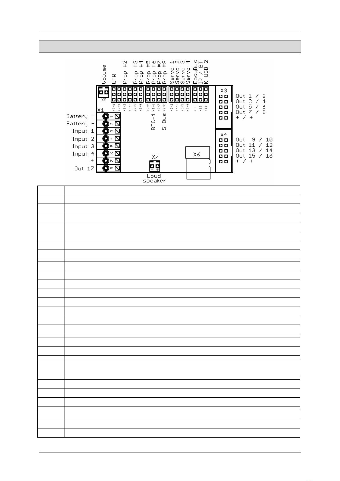
Pin assignment Digital mode
X1/1
Battery + (5 – 15 V)
X1/2
Battery -
X1/3
Input 1
X1/4
Input 2
X1/5
Input 3
X1/6
Input 4
X1/7
Plus connection for outputs (internally connected to X1/1)
X1/8
Switching output 17 (high current, max. 3.0 A)
X2/1
Proportional input #1 (throttel channel)
X2/2
Proportional input #2 (steering channel or 2nd throttel channel)
X2/3
Proportional input #3 (Nautic/Multiswitch 1 / Control Pad 1 / EKMFA)
X2/4
Proportional input #4 (Nautic/Multiswitch 2 / Control Pad 2)
X2/5
Proportional input #5
X2/6
Proportional input #6 / Bluetooth module BTC-1
X2/7
Proportional input #7
X2/8
Proportional input #8 / Sum signal input
X3
Switching outputs 1 - 8
X4
Switching outputs 9 - 16
X5/1 –
X5/4
Servo 1 - 4
X6
Micro SD card
X7
Loudspeaker
X8
Volume control with poti
X9
Kraftwerk EasyBus
X10
Connection for infrared diode or Bluetooth transmitter for light modules
X11
Port for data cable K-USB-2

GB Sound module USM-RC-3
10 BEIER-Electronic 11.10.2021
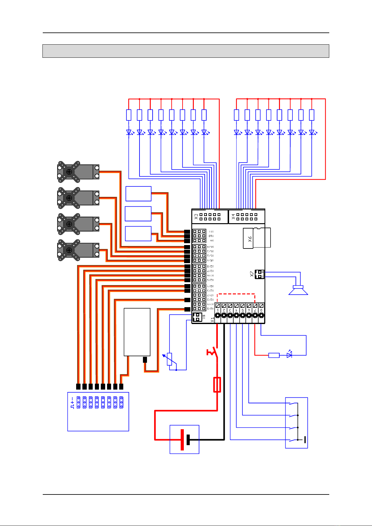
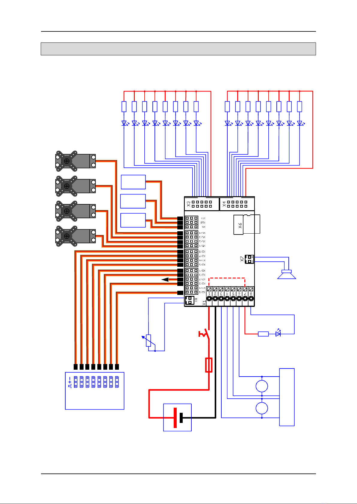
RC receiver
Servo
Servo
1
Servo
2
Servo
3
Volume
100k
Battery
5 - 15 V
(max.
4S LiPo)
+
-
Outputs minus
switching
Servo
4
Servo Servo
Prop #1 (Throttle)
Prop #2 (Steering / 2nd Throttle)
Prop #3
Prop #4
Prop #5
Prop #6 (BTC-1)
Prop #7
Prop #8 (S-BUS, SUMD, i-BUS)
Servo
-
+
Loudspeaker
4 - 8 Ohm
Speed controller
2nd ESC / Steering servo
Kraftwerk
EasyBus
IR / BT
transmitter
Data cable
K-USB-2
e.g. switching module
Input 1
Input 2
Input 3
Input 4
Output 17
(high current,
max. 3 A)
4 A
Fuse
(important!)
Main
switch
USM-RC-3
Micro
SD card
1 - 32 GB
(optional)
+
-
Output 9
Output 10
Output 11
Output 12
Output 13
Output 14
Output 15
Output 16
Output 1
Output 2
Output 3
Output 4
Output 5
Output 6
Output 7
Output 8
braun
red
orange
yellow
green
blue
purple
grey
white / black
brown
red
orange
yellow
green
blue
purple
grey
white / black
Wiring diagram Digital mode
GB Sound module USM-RC-3
11.10.2021 BEIER-Electronic 11
Pin assignment Digital mode with UFR speed controller
X1/1
Battery + (5 – 15 V)
X1/2
Battery -
X1/3
Input 1
X1/4
Input 2
X1/5
Input 3
X1/6
Input 4
X1/7
Plus connection for outputs (internally connected to X1/1)
X1/8
Switching output 17 (high current, max. 3.0 A)
X2/1
Connection for UFR speed controller X4/1
X2/2
Proportional input #2
X2/3
Proportional input #3 (Nautic/Multiswitch 1 / Control Pad 1 / EKMFA)
X2/4
Proportional input #4 (Nautic/Multiswitch 2 / Control Pad 2)
X2/5
Proportional input #5
X2/6
Proportional input #6 / Bluetooth module BTC-1
X2/7
Proportional input #7
X2/8
Proportional input #8 / Sum signal input
X3
Switching outputs 1 - 8
X4
Switching outputs 9 - 16
X5/1 –
X5/4
Servo 1 - 4
X6
Micro SD card
X7
Loudspeaker
X8
Volume control with poti
X9
Kraftwerk EasyBus
X10
Connection for infrared diode or Bluetooth transmitter for light modules
X11
Port for data cable K-USB-2
GB Sound module USM-RC-3
12 BEIER-Electronic 11.10.2021
RC receiver
Servo
Servo
1
Servo
2
Servo
3
Volume
100k
Battery
5 - 15 V
(max.
4S LiPo)
+
-
Outputs minus
switching
Servo
4
Servo Servo
Throttle
Prop #2
Prop #3
Prop #4
Prop #5
Prop #6 (BTC-1)
Prop #7
Prop #8 (S-BUS, SUMD, i-BUS)
Servo
-
+
Loudspeaker
4 - 8 Ohm
Kraftwerk
EasyBus
IR / BT
transmitter
Data cable
K-USB-2
e.g. switching module
Input 1
Input 2
Input 3
Input 4
Output 17
(high current,
max. 3 A)
4 A
Fuse
(important!)
Main
switch
USM-RC-3
Micro
SD card
1 - 32 GB
(optional)
+
-
X1
X4/1
UFR-
1230(-D)
Output 9
Output 10
Output 11
Output 12
Output 13
Output 14
Output 15
Output 16
Output 1
Output 2
Output 3
Output 4
Output 5
Output 6
Output 7
Output 8
braun
red
orange
yellow
green
blue
purple
grey
white / black
brown
red
orange
yellow
green
blue
purple
grey
white / black
Wiring diagram Digital mode with UFR speed controller

GB Sound module USM-RC-3
11.10.2021 BEIER-Electronic 13
Pin assignment Mix mode
X1/1
Battery + (5 – 15 V)
X1/2
Battery -
X1/3
Motor 1 + (speed)
X1/4
Motor 1 - (speed)
X1/5
Motor 2 + (speed)
X1/6
Motor 2 - (speed)
X1/7
Plus connection for outputs (internally connected to X1/1)
X1/8
Switching output 17 (high current, max. 3.0 A)
X2/1
Proportional input #1
X2/2
Proportional input #2
X2/3
Proportional input #3 (Nautic/Multiswitch 1 / Control Pad 1 / EKMFA)
X2/4
Proportional input #4 (Nautic/Multiswitch 2 / Control Pad 2)
X2/5
Proportional input #5
X2/6
Proportional input #6 / Bluetooth module BTC-1
X2/7
Proportional input #7
X2/8
Proportional input #8 / Sum signal input
X3
Switching outputs 1 - 8
X4
Switching outputs 9 - 16
X5/1 –
X5/4
Servo 1 - 4
X6
Micro SD card
X7
Loudspeaker
X8
Volume control with poti
X9
Kraftwerk EasyBus
X10
Connection for infrared diode or Bluetooth transmitter for light modules
X11
Port for data cable K-USB-2
GB Sound module USM-RC-3
14 BEIER-Electronic 11.10.2021
RC receiver
Servo
Servo
1
Servo
2
Servo
3
Volume
100k
Battery
5 - 15 V
(max.
4S LiPo)
+
-
Outputs minus
switching
Servo
4
Servo Servo
Prop #1
Prop #2 (Steering)
Prop #3
Prop #4
Prop #5
Prop #6 (BTC-1)
Prop #7
Prop #8 (S-BUS, SUMD, i-BUS)
Servo
-
+
Loudspeaker
4 - 8 Ohm
Kraftwerk
EasyBus
IR / BT
transmitter
Data cable
K-USB-2
4 A
Fuse
(important!)
Main
switch
USM-RC-3
Micro
SD card
1 - 32 GB
(optional)
+
-
MM
Motor 1 Motor 2
Speed controller
(Option)
+-+-
Output 17
(high current,
max. 3 A)
Steering servo
Output 9
Output 10
Output 11
Output 12
Output 13
Output 14
Output 15
Output 16
Output 1
Output 2
Output 3
Output 4
Output 5
Output 6
Output 7
Output 8
braun
red
orange
yellow
green
blue
purple
grey
white / black
brown
red
orange
yellow
green
blue
purple
grey
white / black
Wiring diagram Mix mode

GB Sound module USM-RC-3
11.10.2021 BEIER-Electronic 15
Pin assignment Analog mode
X1/1
Battery + (5 – 15 V)
X1/2
Battery -
X1/3
Motor 1 + (speed)
X1/4
Motor 1 - (speed)
X1/5
Motor 2 + (speed)
X1/6
Motor 2 - (speed)
X1/7
Plus connection for outputs (internally connected to X1/1)
X1/8
Switching output 17 (high current, max. 3.0 A)
X2/1
Input 1
X2/2
Input 2
X2/3
Input 3
X2/4
Input 4
X2/5
Input 5
X2/6
Input 6
X2/7
Input 7
X2/8
Input 8
X3
Switching outputs 1 - 8
X4
Switching outputs 9 - 16
X5/1 –
X5/4
Servo 1 - 4
X6
Micro SD card
X7
Loudspeaker
X8
Volume control with poti
X9
Kraftwerk EasyBus
X10
Connection for infrared diode or Bluetooth transmitter for light modules
X11
Port for data cable K-USB-2

GB Sound module USM-RC-3
16 BEIER-Electronic 11.10.2021
MM
Motor 1 Motor 2
Speed controller
(Option)
+-+-
Servo
Servo
1
Servo
2
Servo
3
Volume
100k
Battery
5 - 15 V
(max.
4S LiPo)
+
-
Outputs minus
switching
Servo
4
Servo Servo
Servo
-
+
Loudspeaker
4 - 8 Ohm
Kraftwerk
EasyBus
IR / BT
transmitter
Data cable
K-USB-2
e.g. switching module
Output 17
(high current,
max. 3 A)
4 A
Fuse
(important!)
Main
switch
USM-RC-3
Micro
SD card
1 - 32 GB
(optional)
+
-
Input 1
Input 2
Input 3
Input 4
Input 5
Input 6
Input 7
Input 8
Output 9
Output 10
Output 11
Output 12
Output 13
Output 14
Output 15
Output 16
Output 1
Output 2
Output 3
Output 4
Output 5
Output 6
Output 7
Output 8
braun
red
orange
yellow
green
blue
purple
grey
white / black
brown
red
orange
yellow
green
blue
purple
grey
white / black
Wiring diagram Analog mode
GB Sound module USM-RC-3
11.10.2021 BEIER-Electronic 17
Installation
For a safe installation of the sound speed controller, we recommend to use Velcro
tape on the USM-RC-3 cover.
Pay attention not to connect components and conductor tracks with any metal parts!
This may cause a short circuit, which destroys the USM-RC-3!
Connection
The connection of the supply voltage, the loudspeaker and the outputs are always
the same, regardless of whether the module is operated in Digital, Analog or Mixed
mode.
The remaining wiring (receiver, switching inputs) then depends on which operating
mode is used.
Always switch off power before connecting the module!
The terminal X1 is a spring cage terminal which allows a fast and simple connection
of the sound module. To put a wire in or out, simply push from above onto the
actuating lever of the terminal with a small screwdriver. The wires should be
approximately 7 – 8 mm stripped and should ideally be tin-plated prior the
connection.
Connection of supply voltage (battery):
The sound module is designed for a DC voltage from 5 to 15 V. Just connect
terminal X1/1 with the positive pole and terminal X1/2 with the negative pole of the
supply voltage.
Pay attention to a correct connection of the supply voltage poles!
A wrong connection can destroy the sound module!!!
Generally, the drive battery is used for supply voltage. The best thing is to use a Y-
cable, to connect the sound module and the speed controller simultaneously to the
battery.
If you use a separate battery for the sound module, please connect the
negative poles from both batterie. This avoids possible malfunctions.
If the supply voltage is correctly applied, the green LED on the module lights up.
We absolutely recommend putting the supplied fuse (4A) between the positive pole
of the battery and terminal X1/1. This action prevents damage to your model and the
sound module, if the wiring is faulty or in case of a technical failure.

GB Sound module USM-RC-3
18 BEIER-Electronic 11.10.2021
Unfortunately, a fuse can never always protect all wrong connections 100%!
Therefore, please make sure that everything is connected correctly.
As a further option you can also connect a switch into the power supply of the sound
module to switch it off. It is a method which has the advantage of less power
consumption if permanently no sound is needed. But the switching-outputs and
servo-outputs are also disabled if switched off!
Connection of loudspeaker
The loudspeaker ist connected to X7 at the USM-RC-3.
The red cable is connected to the positive and the black to the negative pole of the
loudspeaker.
The supplied loudspeaker connection cables should not be extended to prevent
interference of the receiver (especially with FM systems)! The loudspeaker cable
should be installed with a maximum of distance to receiver and antenna.
Information about power supply of receiver:
The voltage at the terminals X1/1 and X1/2 powers the audio amplifier for the sound
playback, the switching outputs and the rest of the internal electronic of the sound
module.
The receiver is not powered with this voltage. It does not matter, if e.g. a voltage is
connected to X2 over a BEC or a receiver battery.
A BEC voltage from the speed controller is directly connected to the receiver over
the terminals of X2. Connected servos to X5 / 1 - X5 / 4 are also supplied via the
BEC voltage.
Therefore you can plan your receiver's power supply just as if you connect no sound
module. For example for 2 speed controllers with BEC, one BEC must be disabled.
Connection of switching-outputs 1 - 16
The outputs 1 - 16 of the module are located at the pin connectors X3 and X4.
The supplied ribbon cable can be used to connect the outputs. For easier
connection, the terminals AKL-8 and AKL-8-W can be ordered from our shop.
Of course other cables/plugs with a cross section of 0,14 mm² - 0,5 mm² can be
connected as well.
The USM-RC-3 is always switching the negative pole to each output and thus to the
connected load. The negative pole is always connected to the load (see wiring
diagram).

GB Sound module USM-RC-3
11.10.2021 BEIER-Electronic 19
The common positive pole for outputs 1 – 8 and 9 - 16 are the black and white
cables. It is also possible to connect the load directly to the positive pole of the
battery.
Ribon cable assignment:
Output
Ribbon cable (X3)
1
Brown
2
Red
3
Orange
4
Yellow
5
Green
6
Blue
7
Lila
8
Grey
+
White
+
Black
Output
Ribbon cable (X4)
1
Brown
2
Red
3
Orange
4
Yellow
5
Green
6
Blue
7
Lila
8
Grey
+
White
+
Black
The switched voltage at the outputs (with 100% intensity) is always as high, as the
supply voltage of the USM-RC-3. For example if the module is supplied with 12V,
only lamps with 12V should be connected.
If you want to connect LEDs, series resistors are always required. Furthermore,
attention must be paid to the correct polarity of the LED. The series resistors for the
LED’s are depended on the supply voltage, the LED-color and the LED-current.
The table below shows the resistance values required for standard LEDs (approx. 15
mA current):
Supply voltage
Series resistors
6 V
270 Ohm
7,2 V
330 Ohm
8,4 V
470 Ohm
9,6 V
510 Ohm
12 V
680 Ohm

GB Sound module USM-RC-3
20 BEIER-Electronic 11.10.2021
In the internet you will find various pages to calculate the necessay resitor value.
High current output 17
Output 17 is available at terminal X1/8. This output can switch a higher current (max.
3 A) than outputs 1 - 16. This means that loads with a higher current consumption,
such as smoke generators, can be connected here. Terminal X1/7 can be used as
the positive pole. This is internally connected to the plus of the supply voltage (X1/1).
Connection of data cable K-USB-2
The data cable K-USB-2 is connected to X11. The brown cable points to the SD
card.
The speed controller is not powered by the data cable. For using the data cable, the
USM-RC-3 must be supplied with power via the battery as normal.
General remarks for wiring
Always use cables with a core diameter of at least 0.75 mm² for connecting the
power supply. For all other connections, such as lights you can use smaller cables
such as 0.25 mm².
It is important to pay attention to „clean" wire routing. Always use short wires and
avoid any unnecessary loops.
Table of contents


