manuals.online logo
Brands
  1. Home
  2. •
  3. Brands
  4. •
  5. weintek
  6. •
  7. Recording Equipment
  8. •
  9. weintek MT8000iE Series User manual

weintek MT8000iE Series User manual

Installation and Startup Guide
This document covers the installation of MT6000/8000iE Series HMI, for the detailed specifications
and operation, please refer to Brochure and EasyBuilder Pro User Manual.
Install Environment:
NEMA Rating
The MT6000/8000iE Series HMI is NEMA 4 rated (Indoor Use Only).
Electrical
Environment
The MT6000/8000iE Series has been tested to conform to European CE
requirements. This means that the circuitry is designed to resist the effects of
electrical noise. This does not guarantee noise immunity in severe cases. Proper
wire routing and grounding will insure proper operation.
Environmental
Considerations
(1) Make sure that the displays are installed correctly and that the operating
limits are followed. Avoid installing units in environments where severe
mechanical vibration or shocks are present.
(2) Do not operate the unit in areas subject to explosion hazards due to
flammable gases, vapors or dusts.
(3) Do not install the unit where acid gas, such as SO2 exists.
(4) This device should be mounted in the vertical position and for use on the flat
surface enclosure.
(5) Conform to UL508 (ISBN 0-7629-0404-6) machine safety for use in
Pollution Degree 2 Environment.
(6) Relative Humidity: 10% ~ 90% (non-condensing)
Unpacking the Unit
Unpack and check the delivery. If damage is found, notify the supplier.
NOTE:
Place the operator panel on a stable surface during installation. Dropping it or letting it fall may
cause damage.
(1) Installation Instruction, 2-sidedA4 *1
(2) Human Machine Interface *1
(3) Power Connector *1
(4) Brackets & Screws *1 pack
(5) USB Stick Clamp & Tying Strap *1
(6) Fuse 1.25A/250V 5*20mm *1
Installation Instructions
Secure the operator panel in position, using all the fastening holes and the provided brackets
and screws. Screw Torque: 2.6 ~ 3.9 lbf.in. (For reaching waterproof effect and preventing the panel
from being deformed.)
Type
A(mm)
B(mm)
MT6070iE
192
138
MT8070iE
192
138
MT8100iE
260
202
USB Stick Clamp Usage
Combining the USB Stick with the clamp and the tying strap can prevent USB stick from disconnecting
with HMI when strong vibration is present.
1. Insert the USB connector to the clamp and tie them together with the tying strap.
2. Press the spring and insert the USB stick into HMI.
Power Connections
NOTE:
1. Connect positive DC line to the ‘+’ terminal and the DC
ground to the ‘-’ terminal.
2. When downloading project using a USB cable, do not
connect HMI with PLC and PC simultaneously, for
electric potential difference may result in damage to HMI
or PC.
System Settings
When HMI is powered up and displays image,
click the system setting button.
(Default System Password: 111111)
It is necessary to connect the HMI to
your network through a RJ-45 cable.
(N/A for MT6070iE)
MT6000/8000iE series
Installation Instruction
1
2
Go to the Network tab, you may choose
to auto get DHCP IP, or designate your
own IP.
(A)
(B)
Cutout
3
5
4
EasyBuilder Pro Software Settings
Launch EasyBuilder Pro software, select your project file, press F7 shortcut key to open the download
dialog box: Select Ethernet > IP tab > Enter your HMI IP > Click Download to download this project
file to HMI.
If use MT6070iE, please select USB cable.
Using screensaver and backlight saver is recommended in order to avoid image persistence caused
by displaying the same image on HMI for a long time.
( Please refer to EasyBuilder Pro User Manual for software operation details )
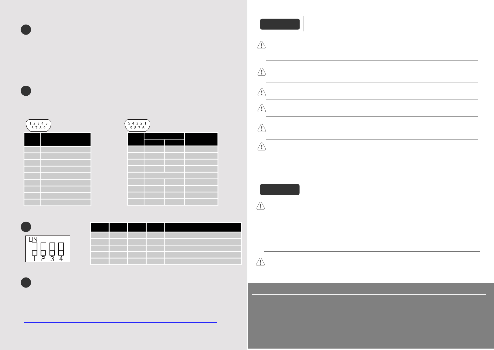
Communication Connections
NOTE: 1. COM1 and COM3 [RS485] 2W support MPI 187.5K, please use one at a time.
2. COM1 [RS485] / COM3 [RS485] with isolation protection. (N/A for MT6070iE)
COM1 RS232, 9 Pin, Male, D-sub COM1/3 RS485, 9 Pin, Female, D-sub
DIP SW Settings
Battery Replacement
Battery replacement shall be performed by qualified personnel only and care must be taken when
handling lithium batteries. For more information on battery replacement and disposal considerations,
please refer to the following link:
http://www.weintek.com/download/MT8000/eng/FAQ/FAQ_103_Replace_Battery_en.pdf
Limited Warranty
This product is limited warranted against defects in design and manufacture.
The proven defective product will either be repaired or replaced, at Weintek’s discretion.
This warranty shall not cover any product which is
(a) Out of warranty period which is 12 months from the manufacturing month of the HMI products.
(b) Damage caused by Force Majeure, accident, negligence, improper installation or misuse.
(c) Product has been repaired or taken apart by unauthorized technicians.
(d) Products whose identification markings have been removed or damaged.
SW1
SW2
SW3
SW4
Mode
ON
OFF
OFF
OFF
Touch Screen Calibration Mode
OFF
ON
OFF
OFF
Hide HMI System Setting Bar
OFF
OFF
ON
OFF
Boot Loader Mode
OFF
OFF
OFF
ON
Not supported
OFF
OFF
OFF
OFF
Normal
Another method to enter touch screen calibration mode: Press and hold
anywhere on the screen for more than 2 seconds when HMI starts.
6
7
8
Power
The unit can be powered by DC power only, voltage range: 24±20% Volts DC, compatible with
most controller DC systems. The power conditioning circuitry inside the unit is accomplished by a
switching power supply. The peak starting current can be as high as 2A.
Fusing
Require-
ments
If the display does not come on within 5 seconds of power up, remove power. An internal fuse will
prevent damage if the polarity of the DC power is incorrect. Check wiring for proper connections
and try to power up again.
High Voltage
An Internal fuse will prevent damage for overcurrent condition however it isn’t guaranteed. DC
voltage sources should provide proper isolation from main AC power and similar hazards.
Emergency
Stop
A Hard-wired EMERGENCY STOP should be fitted in any system using HMI to comply with ICS
Safety Recommendations.
Supply
Voltage
Condition
Do not power the unit and inductive DC loads, or input circuitry to the controller, with the same
power supply. Note: The 24 VDC output from some controllers may not have enough current to
power the
unit.
Wire Routing
a. Power wire length should be minimized (Max: 500m shielded, 300m unshielded).
b. Please use twisted pair cables for power wire and signal wire and conform to the impedance
matching.
c. If wiring is to be exposed to lightning or surges, use appropriate surge suppression devices.
d. Keep AC, high energy, and rapidly switching DC power wiring separated from signal wires.
e. Add a resistor and capacitor in the parallel connection between the ungrounded DC power
supply and the frame ground. This provides a path for static and high frequency dissipation.
Typical values to use are 1M Ohm and 4700pF.
CAUTION
NOTE: Make sure that all local and national electrical standards are met when
installing the unit. Contact your local authorities to determine which codes apply.
Hardware
Considerations
The system designer should be aware that devices in Controller systems could fail and thereby
create an unsafe condition. Furthermore, electrical interference in an operator interface can lead to
equipment start-up, which could result in property damage and/or physical injury to the operator.
If you use any programmable control systems that require an operator, be aware that this potential
safety hazard exists and take appropriate precautions. Although the specific design steps depend on
your particular application, the following precautions generally apply to installation of solid-state
programmable control devices, and conform to the guidelines for installation of Controllers
recommended in NEMA ICS 3-304 Control Standards.
Programming
Considerations
To conform with ICS Safety Recommendations, checks should be placed in the controller to ensure
that all writable registers that control critical parts of plant or machinery have limit checks built into
the program, with an out-of-limit safe shut down procedure to ensure safety of personnel.
GME608IE0_MT6070_8070_8100iE_Installation_170516
DANGER
PIN#
COM1 [RS232]
1
2
RxD
3
TxD
4
5
GND
6
7
RTS
8
CTS
9
PIN#
COM1 [RS485]
COM3
[RS485]
2W
4W
1
Data-
Rx-
2
Data+
Rx+
3
Tx-
4
Tx+
5
GND(COM1)
6
7
Data-
8
Data+
9
GND(COM3)
9

This manual suits for next models

4

Other weintek Recording Equipment manuals

weintek cMT-SVRX Series User manual

weintek

weintek cMT-SVRX Series User manual

weintek cMT3072XP Series User manual

weintek

weintek cMT3072XP Series User manual

weintek cMT3000X Series User guide

weintek

weintek cMT3000X Series User guide

weintek cMT2108X Series User manual

weintek

weintek cMT2108X Series User manual

weintek cMT-3103 User manual

weintek

weintek cMT-3103 User manual

weintek cMT-SVR User guide

weintek

weintek cMT-SVR User guide

weintek cMT2158X Series User manual

weintek

weintek cMT2158X Series User manual

weintek cMT2078X Series User manual

weintek

weintek cMT2078X Series User manual

weintek cMT3072X Series User manual

weintek

weintek cMT3072X Series User manual

weintek MT8070iER1 Series User manual

weintek

weintek MT8070iER1 Series User manual

weintek cMT2128X Series User manual

weintek

weintek cMT2128X Series User manual

weintek cMT-iPC15 User manual

weintek

weintek cMT-iPC15 User manual

weintek cMT3152X Series User manual

weintek

weintek cMT3152X Series User manual

weintek cMT-SVR-200 series User manual

weintek

weintek cMT-SVR-200 series User manual

weintek mTV series User manual

weintek

weintek mTV series User manual

Popular Recording Equipment manuals by other brands

7th Sense Medialon Showmaster Mini Hardware manual

7th Sense

7th Sense Medialon Showmaster Mini Hardware manual

Eding CNC CPU5B user manual

Eding CNC

Eding CNC CPU5B user manual

Data Video HS-1000 instruction manual

Data Video

Data Video HS-1000 instruction manual

Endorphines Milky Way quick start guide

Endorphines

Endorphines Milky Way quick start guide

ICON Cube 2nano user manual

ICON

ICON Cube 2nano user manual

Onq HMS EZ-Scene ALC Instruction/installation sheet

Onq

Onq HMS EZ-Scene ALC Instruction/installation sheet

Blackmagicdesign Audio Monitor Installation and operation manual

Blackmagicdesign

Blackmagicdesign Audio Monitor Installation and operation manual

BOSSCO G6037008-01 owner's manual

BOSSCO

BOSSCO G6037008-01 owner's manual

PEmicro Cyclone MAX user manual

PEmicro

PEmicro Cyclone MAX user manual

Talkaphone ETP-GSM installation instructions

Talkaphone

Talkaphone ETP-GSM installation instructions

BOSSCO GT-1000 Parameter guide

BOSSCO

BOSSCO GT-1000 Parameter guide

Audiodesign PRO PMU 501HS owner's manual

Audiodesign

Audiodesign PRO PMU 501HS owner's manual

ICON iKeyboard 4X user manual

ICON

ICON iKeyboard 4X user manual

Silvercrest SHU 3.1 B2 operating instructions

Silvercrest

Silvercrest SHU 3.1 B2 operating instructions

ICON I-stage owner's manual

ICON

ICON I-stage owner's manual

EMU Proformance Operation manual

EMU

EMU Proformance Operation manual

NAV TOOL GMC Acadia 2013 installation manual

NAV TOOL

NAV TOOL GMC Acadia 2013 installation manual

1010music Toolbox v1.1.5 quick start guide

1010music

1010music Toolbox v1.1.5 quick start guide

manuals.online logo
manuals.online logoBrands
  • About & Mission
  • Contact us
  • Privacy Policy
  • Terms and Conditions

Copyright 2025 Manuals.Online. All Rights Reserved.