Tesseract Modular Step Fader MKII User manual

Step Fader mkII
Step Fader mkII it’s a ‘hands on’ eurorack dual sequencer, featuring two 8 step lines or one with 16 steps plus
quantizer, slew limiter, internal clock generator, CV inputs to control several parameters and more…
Each sequencer has independent settings for the play mode, start point, length, clock divider, transposition
and duty cycle.
The 2 channels of the quantizer can be used for processing external signals, and the same applies for the slew
limiter.
There are also 16 presets to store & recall all the sequencer settings.
The range of the sequencers is 5V approx, and the sum output (CV 1+2) is about 10V.
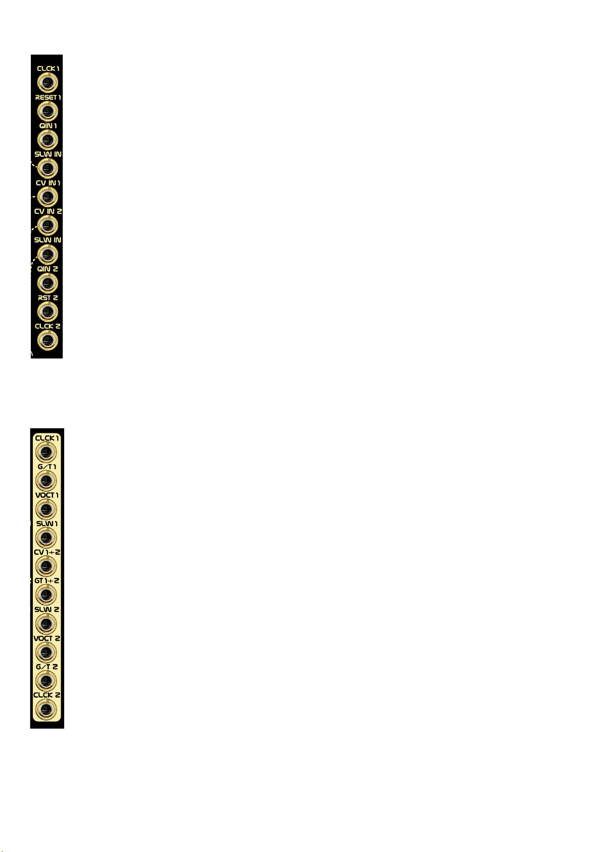
INPUTS
●CLK 1 clock input for sequencer 1 (normalized to CLK 2)
●RESET 1 reset input for sequencer 1
●QIN 1 input for quantizer 1, range 0 to +10 volts
●SLW IN input for the slew limiter 1
●CV IN 1 CV input for modulation
●CV IN 2 CV input for modulation
●SLEW IN input for slew limiter 2
●QIN 2 input for quantizer 2, range 0 to +10 volts
●RESET 2 reset input for sequencer 2
●CLK 2 clock input for sequencer 2
OUTPUTS
●CLK 1 clock output for sequencer 1
●G/T 1 gate & trigger 1 output
●VOCT 1 quantizer 1 output (V/OCT)
●SLW 1 slew limiter 1 output
●CV 1 + 2 sum of both CVs (taken from both slew outs)
●GT 1+2 sum of both G/T outputs (aka OR)
●SLEW 2 slew limiter 2 output
●VOCT 2 quantizer 2 output (V/OCT)
●G/T 2 gate & trigger 2 output
●CLK 2 clock output for sequencer 2

FUNCTION BUTTON AND KEYPAD MODES
The 16 illuminated buttons can be used to set several parameters, even to play the sequencer as a keyboard.
Clicking on the FUNCT button will make the keypad blink, clicking again on one of the 16 illuminated buttons
will select the overall behavior (aka key modes).
The selected key mode will remain active, with the exception of ‘LOAD’ and ‘SAVE’. For those ones, the
previous key mode will be recalled after loading or saving the actual state of the sequencer.
G/T
Gate / Trigger mode (long press will set gate, short set trigger)
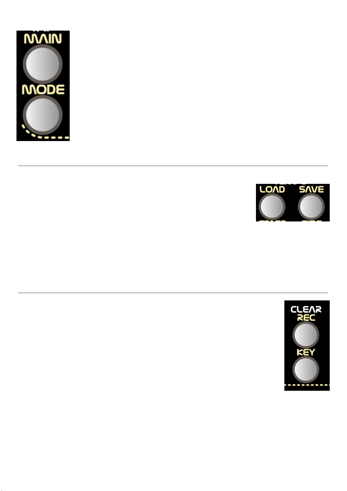
MAIN
sets the ‘Main Setup’ of the module (dual, parallel, single)
LOAD
load preset
SAVE
save preset
SCALE
set the scale for the quantizer of both sequencers
REC
record mode
CV IN 1
set the destination for the CV input 1
CV IN 2
set the destination for the CV input 2
SLIDE
quantizer will do a slide when a step is active
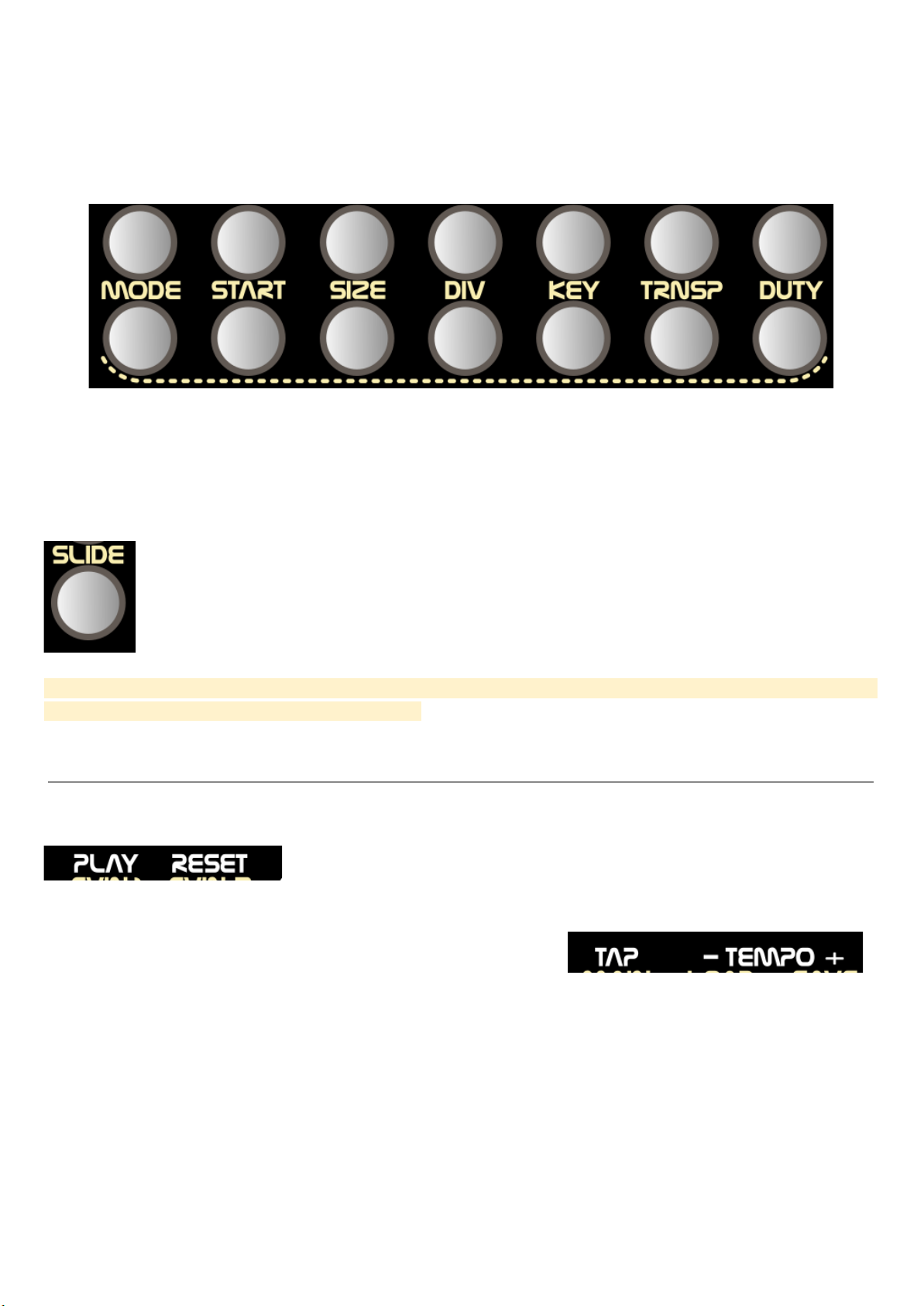
MODE
set the play mode of each sequencer
START
set the starting step of each sequencer
SIZE
set the length of sequencer
DIV
set the clock divider of each sequencer
KEY
use the keypad to play like a sort of keyboard
TRNSP
set the transposition of each quantizer (from -19 to +19 semitones)
DUTY
set the duration of the triggers (from 5 milliseconds to ⅞ of the step length)
SHIFT BUTTON SHORTCUTS
Several settings and actions can be done by pressing the shift button while clicking on the illuminated buttons.
TAP
tap tempo for the internal clock generator
- TEMPO
rests 2 BPM to the internal clock
TEMPO +
adds 2 BPM to the internal clock
REPEAT
set on/off the step repeat / re-trigger (only affects if the clock divider
is bigger that 1)
CLEAR
clears the recorded sequence
PLAY
play / stop for the internal clock
RESET
manual reset for both sequencers
DIV C1
sets on/off the clock division for the clock output 1
DIV C2
sets on/off the clock division for the clock output 2
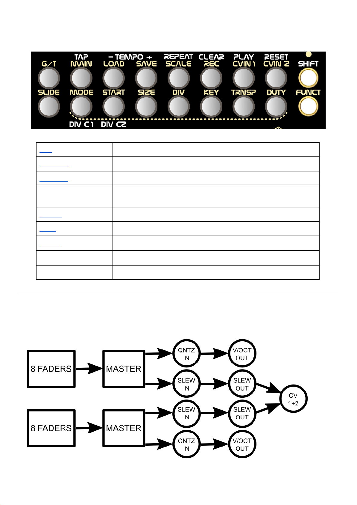
SIGNAL FLOW
The microprocessor controls clocks, gates, quantizers and the position of the sequencers (it decides which
step will be active). The rest of the signal flow is purely analog.
To use the Step Fader mkII as a 16 steps sequencer (main mode = single) a cable from the CV 1+2 has to be
connected to any of the quantizer inputs, if not, each quantizer will process their respective row of faders.
MAIN SETUP AND PLAY MODES
MAIN SETUP:
● DUAL 2 totally independent 8 step sequencers
● PARALLEL one 8 step sequencer with 2 rows of CV
● SINGLE one sequencer up to 16 steps
PLAY MODES:
● Normal
● Reverse
● Pendulum
● Drunk
● Random
PRESETS
Up to 16 presets can be stored and recalled. These presets keep all the sequencer
settings: gate, trigger and slide patterns, main mode, tempo, scale, cv
assignment, play mode, start, size, clock divider, transpose, duty cycle…
Saving a preset will freeze the module for about 10 seconds but loading it is pretty
fast. Obviously the position of the faders is not saved into the presets so loading a preset does not mean that
you’ll get the exact same performance from the module.
After loading or saving a preset, Step Fader mkII will return to the previous key mode.
KEYBOARD, RECORD & CLEAR
The 16 illuminated buttons can be used to play the sequencer as a sort of keyboard in the
KEY mode, but it can also record the played sequence by entering the REC mode. In this
mode, a sequence of 64 steps (no matter what the settings for size are) will memorize the
steps where a key has been pressed. The reset input will force the sequence to start again,
so if you need a shorter sequence than 64 steps use it to determine the length.
To erase the recorded sequence press SHIFT + CLEAR.
If a CV input is assigned to KEY, the play head of that sequencer will be controlled by the cv
input and none of the clocks will have any effect on it.
CV INPUT ASSIGNMENT
The sequencer has 2 CV inputs, which can control only one parameter each. Those parameters are the
MODE,START,SIZE,CLOCK DIVIDER,KEY (position), TRANSPOSE and DUTY CYCLE. Clicking on the
upper row will make that CV input to control a parameter of the first sequencer, and lower row of the second
one.
Please note that if the sequencer main setup is set to PARALLEL or SINGLE, the CV assignment for the
second sequencer (lower row) will have no effect, except for the duty cycle.
Pressing shift when in CV INPUT ASSIGNMENT mode will display the CV read value using the 2 rows of
illuminated buttons as a bar graph..
The slide time can also be controlled by CV (it will affect both sequencers) by clicking on the
leftmost button of the lower row (the SLIDE one) when in the CV assign mode. The concept is
more about adjusting the taste of the slide to your needs, rather than modulating the slide time,
which, on the other hand, can be done.
By default CV IN1 (and so its tall trimmer) is assigned to control the size of the sequencer 1, and CV IN2 the
clock divider (aka step repeat) of the sequencer 2.
INTERNAL CLOCK & TEMPO CONTROL
Step Fader mkII has an internal clock. Hold SHIFT and click on PLAY to start
/stop. SHIFT + RESET will do a manual reset to both sequencers.
The default tempo for the internal clock is 120 BPM. By pressing
SHIFT while clicking on - tempo + the internal clock will
decrease/increase in 2 BPMs. Another way to set the tempo is to
click on the TAP button at the desired speed while pressing shift. One tap for every 4 steps.

QUANTIZER
Step Fader mkII has a built-in 2 channel quantizer with a range of 0 to +10 volts. These quantizers can be
used to process external CV and they are totally independent of the sequencer except for the slide (when
sequencer 1 is on a step with the slide active the quantizer will perform a slide when a voltage change is
received).
Since the inputs of both quantizers have the sequencer outputs normalized to them, a cable from the ‘CV 1 +
2’ output has to be plugged into either quantizer to get the V/OCT output of both rows when the main setup of
the sequencer is set to ‘SINGLE’. In this setup, all slides (top and bottom rows) will affect only the first
quantizer.
The scale of the quantizer can be set using the illuminated buttons by clicking on FUNCT and SCALE, bottom
row represents white keys of the piano and top row the black ones (flat/sharp notes)
scale examples:
Chromatic
C major, A minor
C minor, Eb major
C minor pentatonic with chormatism between IV and V
Raga Charukeshi, C mixolydian b6, F melodic

TRANSPOSE
A transposition of the V/OCT output is possible (this will be applied before the quantizer, so the result will
always be within the set scale). When in this key mode, the upper row of illuminated buttons will set the
transposition for the first sequencer, and the lower row will set the second one.
Each button represents an amount of semitones to be added or subtracted as follows:
The transposition will be the sum of all active buttons. For example, to get +3 semitones, set ON the +1 and
the +2 buttons.
Setting all buttons ON will have the same result as all buttons OFF, so basically, there are several ways to get
the same result. This might seem confusing at first glance, but is a versatile way to manage a range of ±19
semitones with only 8 buttons. Plus, transposing one octave up or down is pretty easy (just click on the -12 or
+12).
Here are some interval examples:
+3 semitones
+12 semitones
+13 semitones
+19 semitones
-12 semitones
-10 semitones

SLIDE AND SLEW LIMITER
These are two different things, the slew limiter it’s an analog circuit that will continuously smooth the voltage
changes present at the slew input (by default the voltage coming from the sequencers), it has no voltage
control, while the slide will perform a glide when it’s active in a step. The slide time can be modified and even
controlled by CV.
AVAILABLE TRANSPOSITION METHODS
There are two methods to apply transposition.
First one is the TRANSPOSE parameter, that will affect the quantizers only and can be controlled by CV,
please note that the minimum voltage for the V/OCT outs is 0V, so negative transposition may not be
performed in the lower notes.
Second method is to use the sum output (CV 1+2), for example, if it’s connected to one of the quantizers input,
the result will be like one sequencer transposing the other, also a voltage can be plugged into one of the slew
inputs to perform that transposition with that external signal.
ADDITIONAL OUTPUTS
In the back of the module there is an 8 pin header with some additional things, they can be connected to a jack
directly with no additional components:
1 & 2 are clock outputs. If a front panel clock out is set to perform the clock division then the additional one
won’t do it …and vice versa.
3is a random gate based on the clock of the sequencer 1.
A&Bare the voltages coming from the sequencers (A for the upper row, B for the lower one). Let’s say
quantizer 1 and slew 1 are processing external volges …in such case, none of the front panel outputs would
be providing the sequencer 1 voltage, so there you have it.
The rest of the pins are ground.

V/OCT CALIBRATION
Assembled units are calibrated already so this step is not necessary, but if you want to calibrate it can always
enter the calibration mode by holding shift while powering the module until the first illuminated button
starts pulsing.
The process is simple:
● Unplug any cable from the CV IN 1 and CV IN 2.
● Power the module, hold shift until the first button shows a pulse.
● Connect a multimeter to the VOCT output.
● The first illuminated button will pulse, that means 0 volts. Use the CV IN 1 & 2 pots to adjust both
V/OCT outputs respectively so you get a value as close to 0 volts as possible.
● Use the illuminated buttons to set other output voltages (the module needs 11 calibration points: 0V,
+1V, +2V…+9V, +10V).
● Use the CV IN 1 and CV IN 2 tall trimmers to adjust the output voltage as close as possible for every
calibration point and V/OCT output (it will change in steps of 3 millivolts, so for 1 volt 1,001v or 0,999v
would a valid value).
● Do not press another button until both outs are calibrated. If some steps have been calibrated and you
go back to any of them, then they have to be calibrated again.
● V/OCT INPUTS CALIBRATION: connect 2 voltage sources to VOCT1 and VOCT2. Input 0 volts and
click on the button 15, input +3 volts and click on button 16.
● To save the settings, press the FUNCT button for about 1 second, this will freeze the module for
several seconds. To exit the calibration mode without saving the settings, first click on the FUNCT
button and then any of the illuminated buttons to enter any other mode.
Table of contents


