Interface BlueDAQ BSC4D User manual

1
4-Channel PC Interface Module and Data
Acquision Instrument BSC4D
BSC4D-D
BSC4D-BT
Operag Manual
Released June 20, 2023


3
Interface Inc. ●7418 East Helm Drive, Scottsdale, Arizona 85260 USA ●www.interfaceforce.com
Table of contents
Strain gage measuring amplifier BSC4D......................................................................................... 5
Description ..................................................................................................................................... 5
Dimensions.................................................................................................................................... 6
Technical data................................................................................................................................ 7
Connection assignment................................................................................................................ 8
Strain gage measuring amplifier BSC4D-BT .................................................................................23
Description ...................................................................................................................................23
Dimensions..................................................................................................................................24
Technical data..............................................................................................................................25
Wiring diagram.............................................................................................................................26
Technical data BSC4D-BT M12..................................................................................................30
Switch configuration BSC4D-BT M12 .......................................................................................32
Measurement resolution.............................................................................................................34
Order variants BSC4D-BT ...........................................................................................................35
Programming / configuration..........................................................................................................36
Scaling of measured values.......................................................................................................36
Measuring range 2.0 mV/V.........................................................................................................36
Measuring range 10.0 mV/V ......................................................................................................36
Measuring range 0.0 to 5 V........................................................................................................37
Measuring range 0.0 to 10 V .....................................................................................................37
Measuring range PT1000...........................................................................................................37
Measuring range K thermocouple cable ..................................................................................38
Commands for configuration .....................................................................................................38
List of commands........................................................................................................................38
Description of commands ..........................................................................................................41
Protocol for measured values...................................................................................................43
Protocol for commands..............................................................................................................44
Protocol for responding to commands.....................................................................................44
Digital IOs.....................................................................................................................................45
analog input.................................................................................................................................. 50
CAN
bus.............................................................................................................................................51
Protocol for measured values...................................................................................................51
Protocol for commands..............................................................................................................51
Protocol for responding to commands.....................................................................................51
Configuring the CAN-ID ..............................................................................................................52
Data frequency and filter.............................................................................................................54
analog filter...................................................................................................................................54
Digital filter....................................................................................................................................54

Annex................................................................................................................................................55
Connection figures for BSC4D-BT SD and BSC4D-BT LD ......................................................55
Warranty
.......................................................................................................................................
58
Interface Inc. ●7418 East Helm Drive, Scottsdale, Arizona 85260 USA ●www.interfaceforce.com
5
Interface Inc. ●7418 East Helm Drive, Scottsdale, Arizona 85260 USA ●www.interfaceforce.com
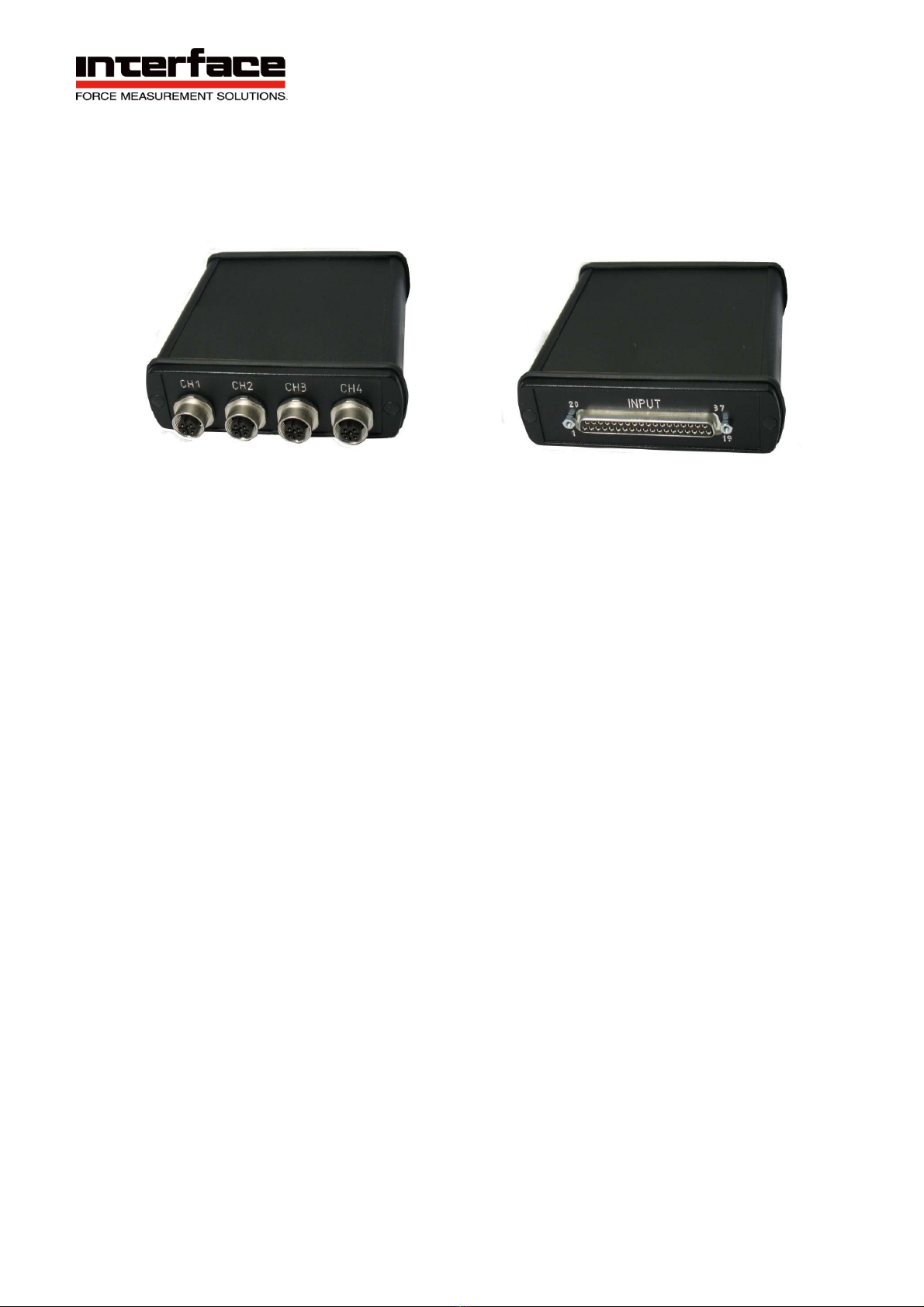
Strain gage measuring amplier BSC4D-D
BSC4D
-C M12 Connectors
Front view sensor connecon
Descrip
BSC4D-D
D37-Pin D-Sub
Front view sensor connecon
•
4-
channels
•
Power supply via USB port
•
Inputs for Strain gage / 0–10 V /
PT1000
•
Measurement ranges 2 mV/V / 10 mV/V
•
Strain gage quarter / half / full bridges
•
8 digital inputs / outputs
This 4-channel measuring ampli for sensors with strain gages is equipped with a USB interface.
The measuring ampli can be delivered with an 37-pin D-Sub connec or with 4x M12 ports.
The measuring amplier has eight digital inputs and outputs.
On the backside 25-pin D-Sub socket, strain gage full-bridges and half-bridges 120 Ohm up to 1 kOhm
as well as PT1000 temperature sensors and 1000 Ohm single grid strain gages or voltages 0 ... 5V
can be connected.
The front-end M12 socket is cured by default for strain gage full-bridge connecns and for
voltage inputs 0 ... 5V and 0 ... 10V.

6
Interface Inc. ●7418 East Helm Drive, Scottsdale, Arizona 85260 USA ●www.interfaceforce.com
Dimensions
Figure 1: Dimensions BSC4D-D 37-pin D-Sub
Figure 2: Dimensions BSC4D-C M12
7
Interface Inc. ●7418 East Helm Drive, Scottsdale, Arizona 85260 USA ●www.interfaceforce.com
Technical data
Accuracy class
0.05
%
Inputs
Resolution 16
Bit
Strain gage inputs
Full bridge
Half bridge
Quarter bridge
89-5000
89-5000
120 / 350 / 1000
Ohm
Ohm
Ohm
Common mode rejection
at 60 Hz common-mode signal
95–110
dB
Measurement frequencies
Data frequency
0 – 500
Hz
Sampling frequency 1.92 MHz
Cut-off frequency
analog
digital
450
Notch filter
Hz
Hz
Outputs
Bridge supply voltage
Current load capacity
2.5
30
Volt
mA
Fixed voltage output
Current load capacity
5
20
V
mA
Switching outputs/inputs
I/O 1-8
Current load capacity:
TTL level
5 (active High)
5
V
mA
Interface
USB
1.1,
USB
2.0
compatible
Supply voltage
Nominal range
Isolation voltage
Current consumption
4.5... 5.5 via USB port
1000
<
200
V DC
Vrms
mA
Temperature range
Nominal temperature range
Storage temperature range
Zero point drift
Sensitivity drift
-
10…+65
-
40…+85
<
0.05
<
0.01
°C
°C
%/10°C
%/10°C
Dimensions
L x W x H 106 x 119 (132) x 32
mm x mm x mm
Prot type / Weight
Protection type IP40
8
Interface Inc. ●7418 East Helm Drive, Scottsdale, Arizona 85260 USA ●www.interfaceforce.com
5
Weight
BSC4D-D
37-pin D-Sub
239 g
Table 1: Technical data BSC4D-D
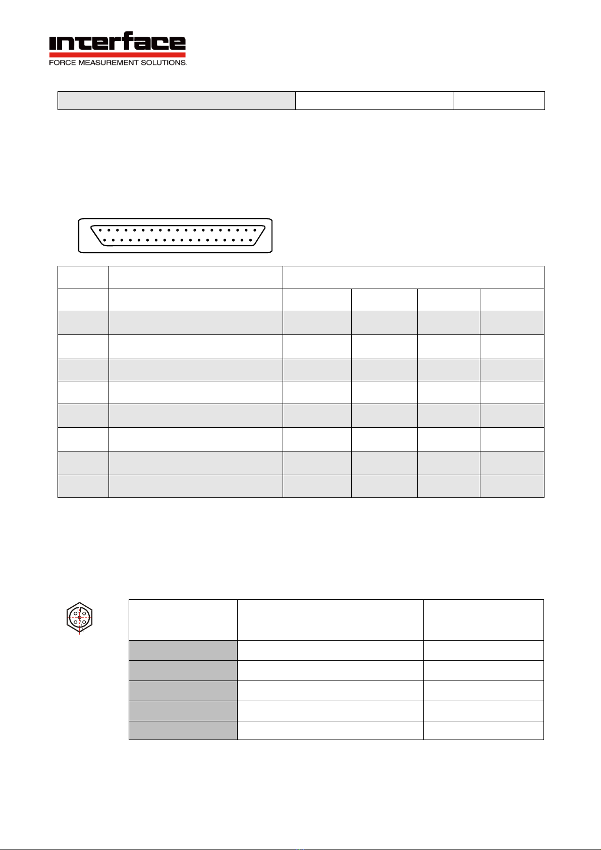
Conneon assignment
Connecon plan for 37-pin D-sub port
19 1
37 20
Table 2: analog inputs
Connecon assignment for BSC4D-C M12
5-pin port M12x1, type 763
Top view:
1 2
4 3
BSC4D-D assignment
37-pin D-sub port (PIN No.)
Channel
1
Channel
2
Channel
3
Channel
4
+USpositive sensor supply 20
2
11 29
+UDpositive differential input 22
4
13 31
QB1000 quarter bridge extension 1kOhm 23
5
14 32
HB half bridge extension 24
6
15 33
-
UD
negative differential input 25
7
16 34
-
US
negative sensor supply 27
9
18 36
UEanalog input 28 10 19 37
screen
1
1
1
1
5-pin
Descripon
Color code for cables
2
-US negative bridge supply white
1
+US positive bridge supply brown
3
+UD positive differential input blue
4
-UD negative differential input black
5
AUX in input without cable grey

9
Interface Inc. ●7418 East Helm Drive, Scottsdale, Arizona 85260 USA ●www.interfaceforce.com
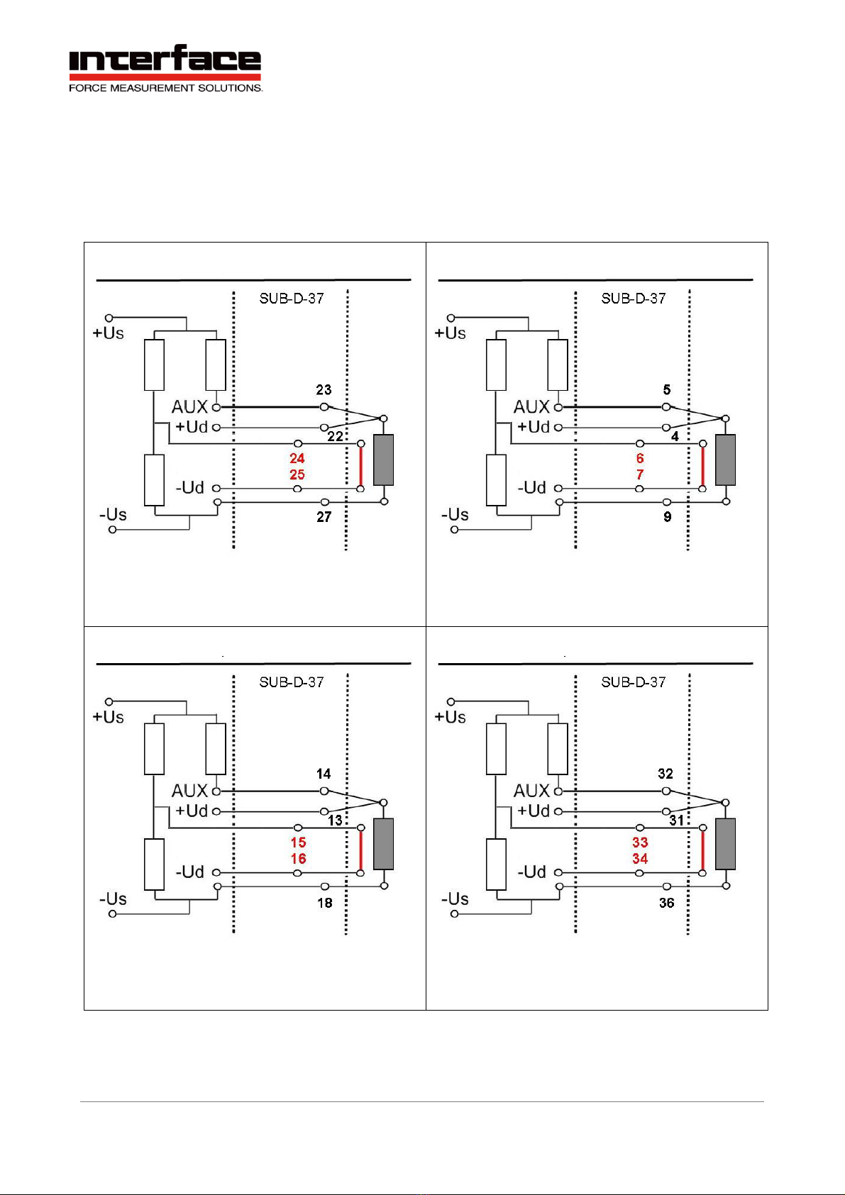
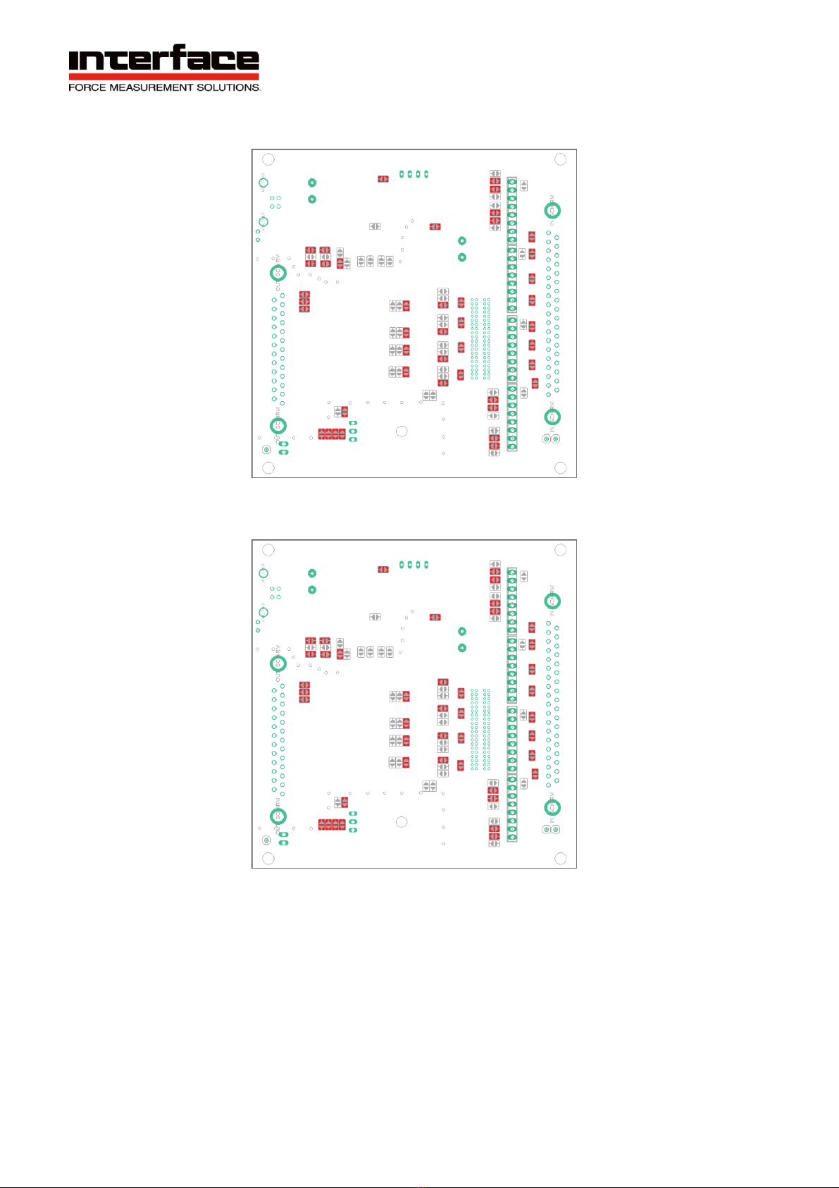
Connecon of full bridge with BSC4D-D 37-pin D-Sub version
The following graphics show the connecon of a full bridge to channel 1 through to channel 4.
BSC4D-D, Channel 1 / full bridge BSC4D-D, Channel 2 / full bridge
BSC4D-D, Channel 3 / full bridge BSC4D-D, Channel 4 / full bridge

Interface Inc. ●7418 East Helm Drive, Scottsdale, Arizona 85260 USA ●www.interfaceforce.com
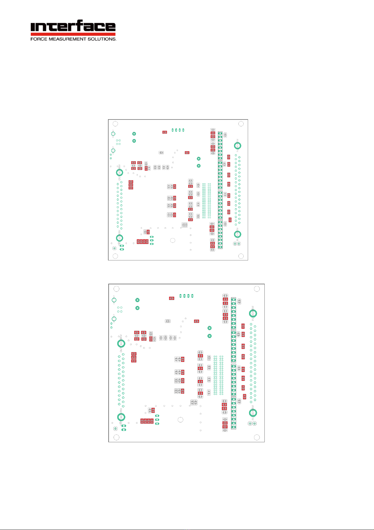
Connecon of half bridge with BSC4D-D 37-pin D-Sub version
The following graphics show the connecon of a half bridge to channel 1 through to
channel 4.
The bridge extension should be adapted depending on the applicaon.
BSC4D-D, Channel 1 / half bridge BSC4D-D, Channel 2 / half bridge
BSC4D-D, Channel 3 / half bridge BSC4D-D, Channel 4 / half bridge
11
Interface Inc. ●7418 East Helm Drive, Scottsdale, Arizona 85260 USA ●www.interfaceforce.com
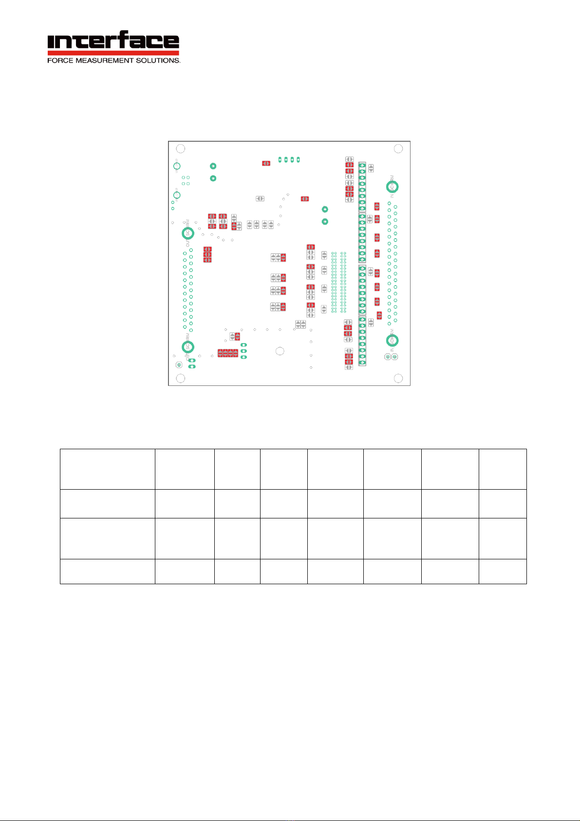
Connecon of quarter bridge with BSC4D-D 37-pin D-Sub version
The following graphics show the connecon of a quarter bridge to channel 1 through to channel 4.
The bridge extension should be adapted depending on the applicaon.
BSC4D-D, Channel 1 / quarter bridge BSC4D-D, Channel 2 / quarter bridge
BSC4D-D, Channel 3 / quarter bridge BSC4D-D, Channel 4 / quarter bridge

Interface Inc. ●7418 East Helm Drive, Scottsdale, Arizona 85260 USA ●www.interfaceforce.com
Connecon of full bridge with BSC4D-C M12 version
The following graphic shows the connecon of a full bridge for the M12 version.
Connecon of half bridge with BSC4D-C M12 version
The following graphic shows the connec of a half bridge for the M12 version. The
bridge extension should be adapted depending on the applican.
Please set the solder bridges:
•
HB1 when using channel 1
with a half bridge.
•
HB2 when using channel 2
with a half bridge.
•
HB3 when using channel 3
with a half bridge.
•
HB4 when using channel 4
with a half bridge.
Solder bridges: Figure 3: Solder bridges for
configuring bridge extensions
see page 11
BSC4D-C, full bridge | M12
BSC4D-C, half bridge | M12
Please close the jumper on the printed circuit
board

13
Interface Inc. ●7418 East Helm Drive, Scottsdale, Arizona 85260 USA ●www.interfaceforce.com
Connecon of quarter bridge or PT1000 with M12 version
The following graphic shows the connec of a quarter bridge for the M12 version. The
bridge extension should be adapted depending on the applican.
Adaptaon of the bridge extension for BSC4D
Opening the device
1.
Remove both screw covers from the input side and remove the fastening screws from the front
cover.
2.
The two hexagonal bolts on the 37-pin D-Sub port must be loosened using a socket
spanner (5 mm).
3.
The printed circuit board is pulled out on the side of the 25-pin D-Sub port.
Adaptaon of the bridge extension with M12 version
The bridge extension can be individually adapted for each channel, for this purpose the device must
be opened and, according to the following gures 1 - 5, the desired soldering bridge must be added.
For PT1000 probes, the addinal resistance 1kOhm is selected.
Please set the solder bridges:
•
HB1 when using channel 1
with a quarter bridge.
•
HB2 when using channel 2
with a quarter bridge.
•
HB3 when using channel 3
with a quarter bridge.
•
HB4 when using channel 4
with a quarter bridge.
Solder bridges: Figure 3: Solder bridges for
configuring bridge extensions
see page 11
BSC4D-C, quarter bridge | M12
Please close the jumper on the printed circuit
board

14
Interface Inc. ●7418 East Helm Drive, Scottsdale, Arizona 85260 USA ●www.interfaceforce.com
Figure 1: M12_standard variant
Figure 2: M12 half bridge
15
Interface Inc. ●7418 East Helm Drive, Scottsdale, Arizona 85260 USA ●www.interfaceforce.com
Figure 3: M12 quarter bridge 1kOhm
Figure 4: M12 quarter bridge 350Ohm

16
Interface Inc. ●7418 East Helm Drive, Scottsdale, Arizona 85260 USA ●www.interfaceforce.com
Figure 5: M12 quarter bridge 120Ohm
The following table explains the curaon opons according to the ures already shown.
Image, Configurati-
on
Plug
Connector
Full
bridge
Half
Bridge
Quarter-
Bridge
350 Ohm
Quarter-
Bridge
120 Ohm
Quarter-
Bridge
1000 Ohm
M12
Standard variant
M12
yes
no
no
no
no
M12
Half Bridge
M12
no *
yes
no
no
no
Quarter Bridge
350Ohm
M12
no *
yes
yes
no
no
Quarter Bridge
120Ohm
M12
no *
yes
no
yes
no
Quarter Bridge
1kOhm
M12
no *
yes
no
no
yes
* Measurement of a full bridge with ac half-bridge is possible, but is carried out with a
measurement error
17
Interface Inc. ●7418 East Helm Drive, Scottsdale, Arizona 85260 USA ●www.interfaceforce.com
Adapng the bridge extension with Sub-D37 version
The bridge extension can be adapted individually for each channel, for this purpose the device must
be opened and, according to the following ures 6 - 8 the desired soldering bridge must be
supplemented.
Figure 6: Sub-D37 standard variant
Figure 7: Sub-D37 quarter bridge 120Ohm
18
Interface Inc. ●7418 East Helm Drive, Scottsdale, Arizona 85260 USA ●www.interfaceforce.com
Figure 8: Sub-D37 quarter bridge 350Ohm
The following table explains the curaon opons according to the ures already shown.
Image, Configurati-
on
P
lug connec
-
tor
Full
bridge
Half
Bridge
Quarter-
Bridge
350 Ohm
Quarter-
Bridge
120 Ohm
Quarter-
Bridge
1000 Ohm
Voltage
input
Sub-D37
Standard variant
Sub-D37
yes
yes
no
no
yes
yes
Sub-D37
Quarter bridge
350Ohm
Sub-D37
yes
yes
yes
no
no
yes
Quarter bridge
120Ohm
Sub-D37
yes
yes
yes
yes
no
yes

19
Interface Inc. ●7418 East Helm Drive, Scottsdale, Arizona 85260 USA ●www.interfaceforce.com
Wiring diagram for posi sensors
The measuring ampli BSC4D must be congured by the manufacturer separately when using it
with potenometric posiensors (linear potenmeters or draw wire displacement sensors)
for the M12 version.
The posi sensor’s wiper is connected to the measuring amplir’s “Aux” input (M12) or “UE“ (37-
pin D-Sub). The posi sensor supplies via the sensor supply +Us and -Us.
5-pin port
37-pin D-SUB port
The potenometric posi sensor is supplied with 2.5 V. The
“Aux” input or UErecords voltages of 0...5 V.
Connecon assignment
Label
5-pin port
37-pin D-SUB port
CH 1
CH 2
CH 3
CH 4
positive supply +Us
1
positive supply +Us 20
2
11 29
negative supply -Us
2
negative supply -Us 27
9
18 36
“Aux” input
5
U
E
input 28 10 19 37
20
Interface Inc. ●7418 East Helm Drive, Scottsdale, Arizona 85260 USA ●www.interfaceforce.com
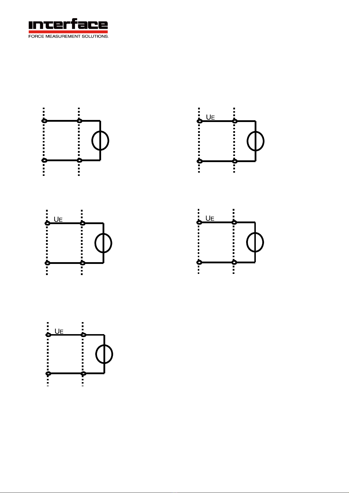
Connection diagram for voltage input 0...5V (0...10V)
The signal to be measured is connected to the input "Aux" (M12) or "UE" (37-pin D-Sub)
of the measuring amplifier. The signal mass is connected to -US/GND.
The input Aux or UEdetects voltages of 0...5V (0...10V).
Drawing 1: 5-pin socket Drawing 2: 37-pin Sub-D socket,
CH 1
Drawing 4: 37-pin Sub-D
socket, CH 2
Drawing 3: 37-pin Sub-D socket,
CH 3
Drawing 5: 37-pin Sub-D
socket, CH 4
UE/Aux
5
-US/GND
2
28
-US/GND
27
10
-US/GND
9
19
-US/GND
18
37
-US/GND
36
Other manuals for BlueDAQ BSC4D
2
This manual suits for next models
2
Table of contents
Other Interface Recording Equipment manuals


