Beijer Electronics X2 control User manual

X2extreme7
English
MAEN249B,2021-11

Foreword
InstallationmanualforX2extreme7
Foreword
All operator panels are developed to satisfy the demands of human-machine
communication. Built-in functions such as displaying and controlling text,
dynamic indication, time channels, alarm and recipe handling are included.
The operator panel works primarily in an object-oriented way, making it easy to
understand and use. Configuration is carried out on a PC using iX Developer
software. The project can then be transferred and stored in the operator panel
itself.
Various types of automation equipment such as PLCs, servos or drives can be
connected to the operator panels. In this manual, the term “the controller” refers
to the connected equipment.
This manual explains how to install the operator panel. Please refer to the
iX Developer reference manual for further information.
Order no: MAEN249B
Copyright © 2021-11 Beijer Electronics AB. All rights reserved.
The information in this document is subject to changewithoutnoticeandisprovidedasavailableatthe
time of printing. Beijer Electronics AB, including all its group companies, reserves the right to change any
information without updating this publication. Beijer Electronics AB, including all its group companies,
assumesnoresponsibilityforanyerrorsthatmayappearinthisdocument. Readtheentireinstallation
manual prior to installing and using this equipment. Only qualified personnel may install, operate or repair
this equipment. Beijer Electronics AB, including all its group companies, are not responsible for modified,
altered or renovated equipment. Because the equipment has a wide range of applications, users must acquire
the appropriate knowledge to use the equipment properly in their specific applications. Persons responsible
for the application and the equipment must themselves ensure that each application is in compliance with
all relevant requirements, standards and legislationinrespecttoconfigurationandsafety. Onlypartsand
accessories manufactured according to specifications set by Beijer Electronics AB, including all its group
companies, may be used.
BEIJER ELECTRONICS AB, INCLUDING ALL ITS GROUP
COMPANIES, SHALL NOT BE LIABLE TO ANYONE FOR ANY
DIRECT, INDIRECT, SPECIAL, INCIDENTAL OR CONSEQUENTIAL
DAMAGES RESULTING FROM THE INSTALLATION, USE OR
REPAIR OF THIS EQUIPMENT, WHETHER ARISING IN TORT,
CONTRACT, OR OTHERWISE. BUYER'S SOLE REMEDY SHALL
BE THE REPAIR, REPLACEMENT, OR REFUND OF PURCHASE
PRICE, AND THE CHOICE OF THE APPLICABLE REMEDY SHALL
BE AT THE SOLE DISCRETION OF BEIJER ELECTRONICS AB,
INCLUDING ALL ITS GROUP COMPANIES.
BeijerElectronics, MAEN249B

Contents
Contents
1 SafetyPrecautions ....................................................... 4
1.1 General ........................................................... 4
1.2 Hazardous Materials ............................................. 4
1.3 DisposalRequirementsUnderWEEERegulations ........... 5
1.4 UL and cUL Installation ......................................... 5
1.5 IECEx/ATEX Certificate and Dust Rating .................... 6
1.6 ConditionsofSafeUseforZone2/22ATEX/IECEx .......... 7
1.7 DuringInstallation .............................................. 7
1.8 DuringUse ....................................................... 7
1.9 Service and Maintenance ........................................ 7
1.9.1 CleaningtheDisplay ............................................ 8
1.10 Dismantling and Scrapping ..................................... 8
1.11 Appearance of Air in Touch Screen ............................. 9
2 NamingConvention .................................................... 10
3 Installation ............................................................... 11
3.1 SpaceRequirements ............................................. 11
3.2 InstallationProcess .............................................. 11
3.2.1 ConnectionstotheController ..................................13
3.2.2 HazardousLocationInstallation ................................14
3.2.3 OtherConnectionsandPeripherals .............................14
4 TechnicalData ........................................................... 15
4.1 CompassSafeDistance .......................................... 16
5 ChemicalResistance .................................................... 17
5.1 MetalCasing ..................................................... 17
5.2 Touch Screen and Overlay Material ............................ 17
5.2.1 ProtectiveFilm ...................................................17
5.2.2 TouchScreenSurface ............................................19
5.2.3 TouchScreenProtector ..........................................19
6 OperatorPanelDrawings .............................................. 20
6.1 Connectors ....................................................... 20
6.1.1 CommunicationPorts ...........................................20
6.2 X2extreme7Outline ............................................ 21
7 Additional Installation Tips ............................................ 23
7.1 Grounding the operator panel .................................. 23
7.2 EthernetConnectionintheOperatorPanel ................... 24
7.3 To Achieve Better EMC Protection ............................. 25
7.4 AmbientTemperature ........................................... 26
7.5 Safety ............................................................. 28
7.6 GalvanicIsolation ................................................ 29
7.7 Cable and Bus Termination RS-485 ............................ 31
7.8 CANInterface ................................................... 31
7.8.1 CableRecommendations ........................................31
7.8.2 Termination .....................................................31
7.8.3 RestrictionsandRecommendations ............................32
7.9 ImageSticking ................................................... 32
BeijerElectronics, MAEN249B

Safety Precautions
1SafetyPrecautions
Both the installer and the owner and/or operator of the operator panel must read
and understand this installation manual.
1.1 General
•Read the safety precautions carefully.
•Check the delivery for transportation damage. If damage is found, notify the
supplier as soon as possible.
•Do not use the operator panel in an environment with high explosive hazards.
•The supplier is not responsible for modified, altered or reconstructed
equipment.
•Use only parts and accessories manufactured according to specifications of
the supplier.
•Read the installation and operating instructions carefully before installing,
using or repairing the operator panel.
•Neverallowfluids,metalfilingsorwiringdebristoenteranyopeningsinthe
operator panel. This may cause fire or electrical shock.
•Only qualified personnel may operate the operator panel.
•Storing the operator panel where the temperature is lower/higher than
recommended in this manual can cause the LCD display liquid to
congeal/become isotropic.
•The LCD display liquid contains a powerful irritant. In case of skin contact,
wash immediately with plenty of water. In case of eye contact, hold the eye
open,flushwithplentyofwaterandgetmedicalattention.
•Thefiguresinthismanualserveanillustrativepurpose. Becauseofthemany
variables associated with any particular installation, the supplier cannot
assume responsibility for actual use based on the figures.
•The supplier neither guarantees that the operator panel is suitable for your
particular application, nor assumes responsibility for your product design,
installation or operation.
•It is recommended to turn on and shut down the operator panel at least once
before installing any components/cards or before connecting the operator
panel to external devices; for example serial devices.
•For Marine panels only:
–The operator panel must be installed and operated as described in this
document to meet this certification.
–Observe precautions for handling electrostatic discharge sensitive devices
1.2 HazardousMaterials
Toxicandhazardousmaterialsorelements
有毒和有害的材料或元素
Partdescription
零件描述
Pb Hg Cd Cr6+ PBB PBDE
PCBandelectronic
components
PCB和电子元件
XOO O O O
O:Indicatesthatthistoxicorhazardoussubstancecontainedinallofthehomogenous
materialsforthispartisbelowthelimitrequirementinSJ/T11363–2014.
BeijerElectronics, MAEN249B 4

Safety Precautions
O:表示该有害物质在该部件所有均质材料中的含量均在 SJ/T11363–2014规定的限
量要求以下。
X:Indicatesthatthistoxicorhazardoussubstancecontainedinatleastoneofthe
homogenousmaterialsforthispartisabovethelimitrequirementinSJ/T11363–2014.
X:表明该有害物质至少在部件的某一均质材料中的含量超出SJ/T11363–2014规定
的限量要求。
1.3 DisposalRequirementsUnder
WEEERegulations
For professional users in the European Union: If you wish to discard electrical
and electronic equipment (EEE), please contact your dealer or supplier for further
information.
For disposal in countries outside of the European Union: If you wish to discard
this product please contact your local authorities or dealer and ask for the correct
method of disposal.
1.4 ULandcULInstallation
•All devices have to be supplied by a Class 2 power supply.
Warning:
Donotseparatewhenenergized.
AVERTISSEMENT,NEPASSEPARERSOUSTENSION.
Warning:
Donotopenwhenanexplosiveatmosphereispresent.
NEPASOUVRIRSIUNEATMOSPHEREEXPLOSIVEESTPRÉSENT.
Warning:
Batterymayexplodeifmistreated. Donotrecharge,disassembleordispose
ofinfire.
Thisproductcontainsabatterythatisnotuserreplaceable.
LABATTERIEPEUTEXPLOSERENCASDEMAUVAISEMANIPULATION.
NELARECHARGEZPAS,NELADÉMONTEZPASETNELAJETEZ
PAS DANS LE FEU.
CEPRODUITCONTIENTUNEPILEQUINEPEUTPASÊTRE
REMPLACÉEPARL'UTILISATEUR.
Warning:
Potentialelectrostaticcharginghazard,seeinstrucions.
Toavoidelectrostaticchargebuild-up,itmustnotberubbedorcleanedwith
solventsoradryclothwheninstalled/usedwithinapotentiallyexplosive
atmosphere.
BeijerElectronics, MAEN249B 5

Safety Precautions
POTENTIELÉLECTROSTATIQUERISQUEDECHARGEMENT,
VOIRINSTRUCTIONS.
Warning:
Explosionhazard! Substitutionofcomponentsmayimpairsuitabilityfor
ClassI,Division2.
RISQUED'EXPLOSION!LASUBSTITUTIONDECOMPOSANTSPEUT
NUIREÀLACONFORMITÉDECLASSEI,DIVISION2.
•Use minimum 85°C copper conductors only.
•To make wiring connections to the power supply connector, follow the table
with cable and torque specifications below:
•ThesedevicesareClass2suppliesprogrammablecontrollers(industrialPCs)
or the use in industrial control equipment and are intended to be (front) panel
mounted.
•For use on a flat surface of an enclosure.
TerminalBlockConnector WireSize Torque(Nm)
PhoenixContact 0.5–3.3mm20.6–0.8
Caution:
Theequipmentshallbeinstalledinanenclosurethatprovidesadegreeofprotection
notlessthanIP66inaccordancewithEN/IEC60079-0whenusedinZone2/22
applications.
Theinsideoftheenclosurethedeviceismountedinshallnotbemorethanpollution
degree2,asdefinedinEN/IEC60664-1.
CETÉQUIPEMENTESTTESTÉENTANTQUECOMPOSANTETDOITÊTRE
INSTALLÉDANSUNBOÎTIERAVECINDICEDEPROTECTIONIP66MINIMUM.
Caution:
TemperaturecodeT4IEC/EN60079-0,IEC/EN60079-7,IEC/EN60079-15andIEC/
EN60079-31.
ProtectionstringExecnCIICT4GcandExtcIIICT82°CDc.
CODESDETEMPÉRATURET4IEC/EN60079-0,IEC/EN60079-7,IEC/EN60079-15et
IEC/EN60079-31.
CHAîNEDEPROTECTIONExecnCIICT4GcetExtcIIICT82°CDc.
1.5 IECEx/ATEXCertificateandDust
Rating
II3GExecnCIICT4Gc
II3DExtcIIICT82°CDc
BeijerElectronics, MAEN249B 6

Safety Precautions
1.6 ConditionsofSafeUseforZone
2/22ATEX/IECEx
•In a Zone 2 environment, this equipment shall be installed in an enclosure
that provides a degree of protection not less than IP54 in accordance with
IEC/EN 60079-0. The IP rating of the equipment is limited to the IP rating
of the enclosure it is to be installed into.
•In a Zone 22 environment, this equipment shall be installed in an enclosure
that provides a degree of protection not less than IP64 in accordance with
IEC/EN 60079-0. The IP rating of the equipment is limited to the IP rating
of the enclosure it is to be installed into.
•To avoid electrostatic charge build-up, it must not be rubbed or cleaned with
solvents or a dry cloth when installed/used within a potentially explosive
atmosphere.
•Theareathedeviceismountedinshallnotbemorethanpollutiondegree2,as
defined in IEC/EN 60664-1.
1.7 DuringInstallation
•Install the operator panel according to the accompanying installation
instructions.
•Ground the operator panel according to the accompanying installation
instructions.
•Only qualified personnel may install the operator panel.
•Separate the high voltage, signal, and supply cables.
•Make sure that the voltage and polarity of the power source is correct before
connecting the operator panel to the power outlet.
•Peripheral equipment must be appropriate for the application and location.
1.8 DuringUse
•Keep the operator panel clean.
•Emergency stop and other safety functions may not be controlled from the
operator panel.
•Do not use excessive force or sharp objects when operating the touch screen.
1.9 ServiceandMaintenance
•Only qualified personnel should carry out repairs.
•The agreed warranty applies.
•Before carrying out any cleaning or maintenance operations, disconnect the
equipment from the electrical supply.
•Clean the display and surrounding front cover with a soft cloth and mild
detergent.
•The battery must be replaced by an authorized Beijer Electronics service
center.
BeijerElectronics, MAEN249B 7

Safety Precautions
1.9.1 CleaningtheDisplay
We recommend using a dry, clean cloth to wipe off dust regularly. Use alcohol or
ammonia-based cleaning agent for cleaning only when necessary. When other
solvents or cleaning agents are used, be sure to follow manufacturers’ instructions.
The agent should be applied to a clean cloth and should not be sprayed directly
onto the panel surface. After cleaning the agent should be removed.
Ammonia based glass cleaners (typically 5-10% ammonia) or 75% alcohol can be
used to clean the surface of PCAP and resistive touch panels.
When you clean the surface of your touch panel, please follow these steps:
1. Apply cleaning agent (alcohol, bleach, or glass cleaner) to a clean cloth. Make
sure the cloth is well saturated.
2. Wipe touch panel in a “Z” motion on the touch panel surface.
3. Dry the panel thoroughly with a dry cloth, removing as much of the cleaning
solution as possible.
4. Do not mix bleach and ammonia because this will produce a dangerous
chemical reaction.
5. Please do not spray cleaning solution directly onto the touch panel surface.
Note:
•Cleaningsolutionscontainingbleach,alcohol,andammoniaarecorrosiveto
touchpanelsurfacecoatingsandITOfilm. So,youshouldnotleavethesolutionon
thetouchpanelsurfaceformorethan2minutes. Makesuretoremoveallresidue
whenfinishedcleaning.
•Donotusesharptoolstocleanthesurfaceofthetouchscreen.
•Donotuseairguns,waterjets,orsteam,tocleanthesurfaceoftouchscreensas
theymaydamagetouchscreenfunctionality.
•Ifcondiments,food,ordrinksarespilledonthesurfaceofthetouchscreen,please
removethemimmediately.
•Ensuremoisturedoesnotseepthroughthecableconnectionareafromtheedges
duringcleaning.
1.10 DismantlingandScrapping
•The operator panel or parts thereof shall be recycled according to local
regulations.
BeijerElectronics, MAEN249B 8

Safety Precautions
•The following components contain substances that might be hazardous to
health and the environment: lithium battery, electrolytic capacitor, and
display.
1.11 AppearanceofAirinTouchScreen
The layer structure of the touch screen contains air. In rare cases, the appearance
of bubbles can arise. This is purely cosmetic and does not affect the functionality
of the operator panel. The appearance can occur under certain environmental
conditions such as temperature, humidity, and atmospheric pressure.
BeijerElectronics, MAEN249B 9

Naming Convention
2 NamingConvention
The name of each panel is based on its properties according to the table below.
X2family Size(inches) Genera-
tion/Version Variant
base
pro
marine(=with
BL)
control(=with
SC)
motion(=with
SM)
extreme
4
5
7
10
12
15
21
v2 SC
SM
HB
HP
BL
12V
SL
RO
CO
web
SoftControl
SoftMotion
HighBrightness
HighPerformance
Black
12Volt
Sealed
RuggedOnly
CertificationOnly
Examples:
•X2 base 5 v2
•X2 pro 7
•X2 control 10
•X2 marine 12 SC
•X2 marine 15 HB SC
•X2 extreme 7 12V*
•X2 extreme 12 HP SC*
•X2 extreme 7 SL HP*
•X2 extreme 12 SL HP SC*
•X2 extreme 7 CO*
•X2 extreme 12 SL HP RO
Note:
Notallcombinationsareavailable.
Note:
*indicatesvariantsincludingIECEx\ATEXandC1D2accreditation.
BeijerElectronics, MAEN249B 10
Installation
3Installation
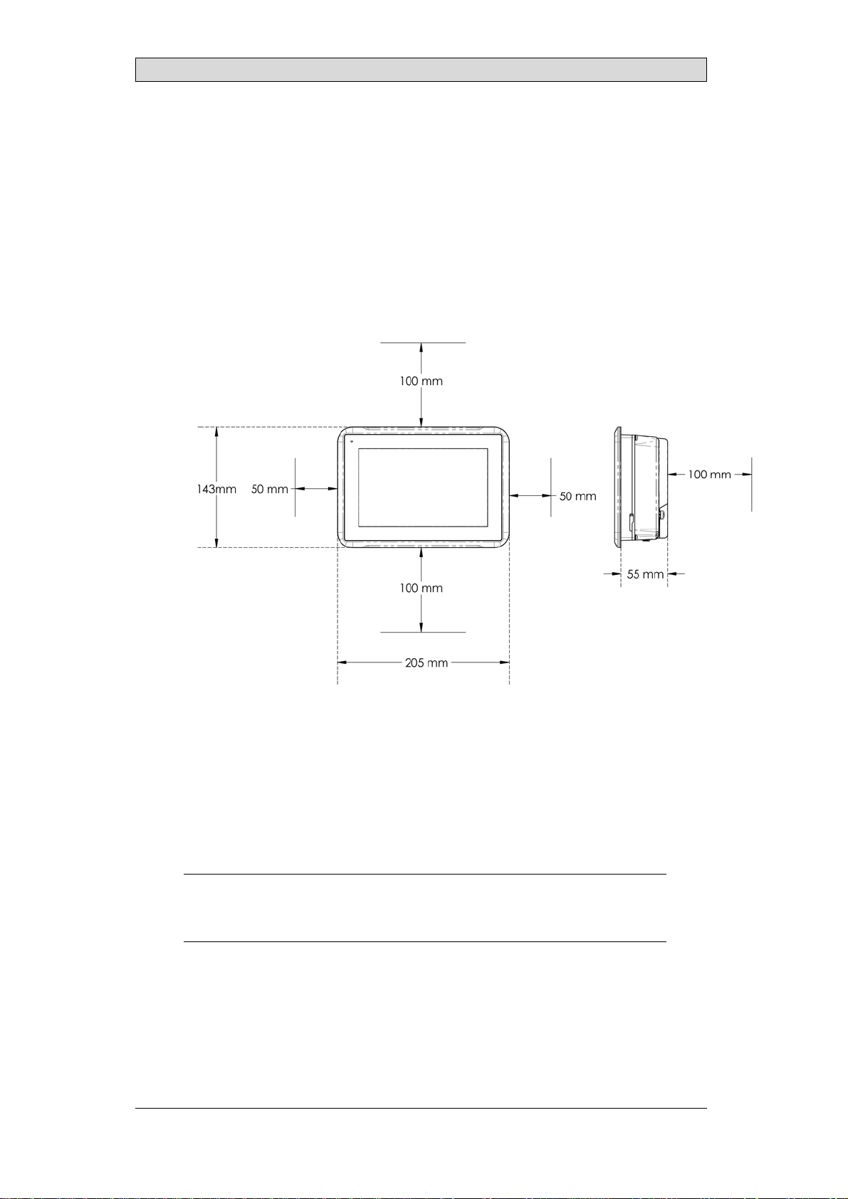
3.1 SpaceRequirements
•Maximum installation plate thickness: 7 mm .
•Installation plate thickness range: 2 - 7 mm +/- 0.1 mm.
The following drawings show the space requirements in millimeters when
installing the operator panel. The drawings are only illustrative and may be out of
proportion.
3.2 InstallationProcess
The following is needed:
•A Phillips/slot screwdriver
Do the following:
1. Unpack and check the delivery. If damage is found, notify the supplier.
Note:
Placetheoperatorpanelonastablesurfaceduringinstallation.
Droppingtheoperatorpanelorlettingitfallmaycausedamage.
2. To c u t a c o r re ct opening for the operator panel, use the cut out dimensions
in the outline drawing. A separate cut out drawing is available for download
from the Beijer Electronics web site. For more information, see sections
Operator Panel Drawings and Technical Data.
BeijerElectronics, MAEN249B 11

Installation
3. Make sure that the mounting surface of the cutout is smooth and cleaned from
any burrs or debris.
4. Install the operator panel into the cutout.
5. Secure the operator panel in position by inserting and sliding the terminal
mounting clips into position as shown. Screw the slotted thumb screws
clockwise, allowing the screws to tighten against the cabinet.
Tighten the screws to 0.7 Nm ± 0.2 Nm.
6. In cases where the front panel seal is critical, install terminal mounting
ring and use a torque wrench to ensure all screws are torqued within the
specification above. For IP66 UL/NEMA Type 4X, Type12, panel must
maintain a flatness < 1 mm overall and < 0.05 mm/mm with a surface
roughness, Ra < 1.6 μm
7. Installation to be through an EPL (Db)(Dc) enclosure for the applicable Dust
Group, Temperature classification and Ambient temperature range.
BeijerElectronics, MAEN249B 12
Installation
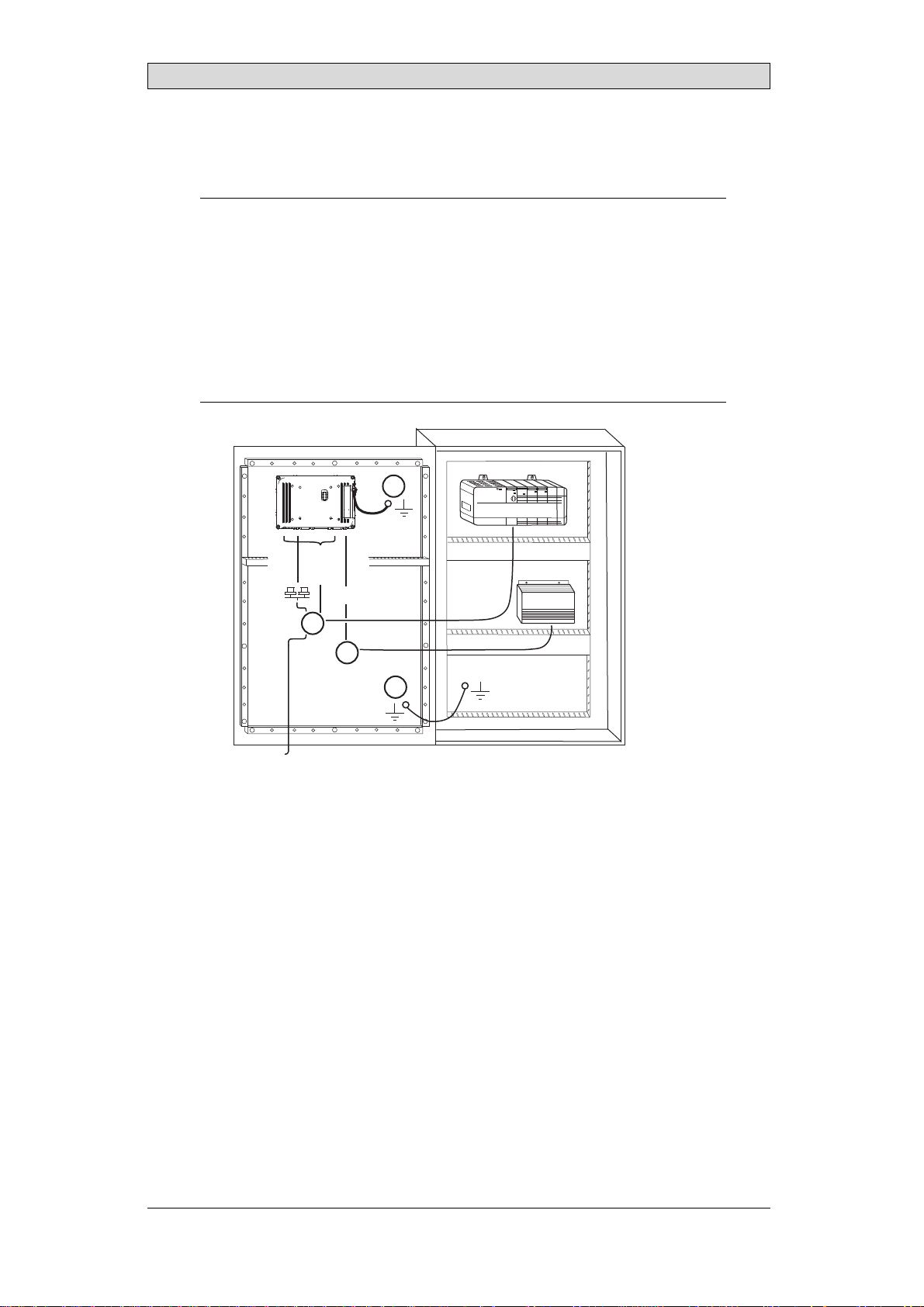
8. Connect the cables in the specified order, according to the drawing and steps
below.
Caution:
•Theoperatorpanelmustbebroughttoambienttemperaturebeforeitisstarted
up. Ifcondensationforms,ensurethattheoperatorpanelisdrybeforeconnecting
ittothepoweroutlet.
•Ensurethattheoperatorpanelandthecontrollersystemhavethesameelectrical
grounding(referencevoltagelevel),otherwiseerrorsincommunicationmay
occur.
•Ensurethatthevoltageandpolarityofthepowersourceiscorrect.
•Separatehighvoltagecablesfromsignalandsupplycables.
•Shieldedcommunicationcablesarerecommended.
24V DC
RS232/
RS422/
RS485
24V DC
A
D
Controller
Power
B
Ethernet
C
The image is illustrative only and may differ slightly from the actual panel.
–Connect cable A.
–Connect cable B, using 14-20 AWG (2.08–0.52 mm2), 180–220 N-cm
torque.
–Connect cable C.
–Connect cable D. The recommended cross-section of the cable is 1.5
mm2.
9. Carefully remove the protective film over the operator panel display, take care
to avoid static electricity that could damage the panel.
3.2.1 ConnectionstotheController
For information about the cables to be used when connecting the operator panel to
the controller, please refer to the help file for the driver in question.
BeijerElectronics, MAEN249B 13
Installation
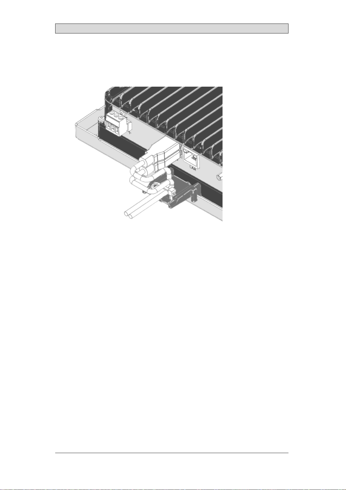
3.2.2 HazardousLocationInstallation
Connect the desired cables and attach them to strain relief plate with cable ties
provided.
3.2.3 OtherConnectionsandPeripherals
Cables, peripheral equipment and accessories must be suitable for the application
and its environment. For further details or recommendations, please refer to the
supplier.
BeijerElectronics, MAEN249B 14

Technical Data
4TechnicalData
Parameter X2extreme7
Frontpanel,W×H×D 205×143×7mm
Cutoutdimensions,
W×H 188±1mm×127±1mm
Maximumcornerradius:4mm.394x270mm.
Mountingdepth 55mm(155mmincludingclearance)
Frontpanelseal IP66UL/NEMAType4X,Type12
Rearpanelseal IP20
Touchscreen
material Polyesteronglass,ITOfilm,resistive
Frameoverlay AutoflexEBA180L
Touchscreen
operations 1millionfingertouchoperations
Reverseside
material Powder-coatedaluminum
Framematerial Powder-coatedaluminum
Weight 1.2kg
CPU i.MX6DualLite
DualARMCortex-A9Core
800MHz
512kBL2cache
Serialports StandardD-sub(9Pin,female)
COM1: RS-232withRTS/CTS
COM2: RS-422/RS-485
COM3: RS-485
1×RS-232Rx/TxwithRTS/CTSand1×RS-422,or2×RS-485
or2×CAN2.0B
*NotsupportedforX2control7/10/15weborX2extreme
7/12/15HPweb.
Ethernet 10/100MbitBase-T(shieldedRJ45withLEDs)
USB StandardUSBTypeAconnector,dualstackhorizontal
SupportsuptoUSB2.0HighSpeed
Externalstorage
media 1×SDcard
Flashmemory
(application
memory)
1.5GBSSD(eMMC)
MemoryRAM 1GBDDR3
NVRAM N/A
LED 1×Multicolor
Realtimeclock Yes
Battery BR2330A/GANlithiumbattery,
nonreplaceable
Powerconsumption
atratedvoltage 10W
Fuse InternalDCfuse,4ATSMT
BeijerElectronics, MAEN249B 15
Technical Data
Parameter X2extreme7
Powersupply +24VDC(18–32VDC)
CE:Thepowersupplymustconformwiththerequirements
accordingtoEN/IEC60950andEN/IEC61558-2-4.
ULandcUL:Thepowersupplymustconformwiththe
requirementsforclass2powersupplies.
Display TFT-LCDwithLEDbacklight
800×480pixels,262kcolors
Activeareaofdisplay 7”diagonal
Pixelerrors ClassI(ISO9241-307)
Backlightbrightness 500Cd/m2
Backlightlifetime 50,000hours
Operating
temperature -30°Cto+70°C
Storagetemperature -40°Cto+80°C
Relativehumidityin
operation 5%–95%non-condensation
Vibration 4g,accordingtoEN/IEC60068-2-6,TestFc
Mechanicalshock 40g,half-sine,11msaccordingtoEN/IEC60068-2-27
Approvalsand
certifications CE/FCC/KCC
Informationisavailableonwww.beijerelectronics.com
ULapproval Informationisavailableonhttp://www.beijerelectron-
ics.comand/orhttps://UL.com
Marinecertificates Informationisavailableonwww.beijerelectronics.com
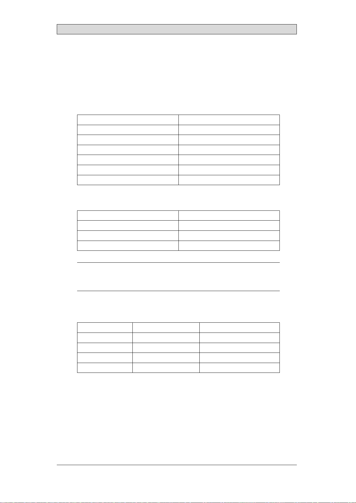
4.1 CompassSafeDistance
Variant Condition Standard
Compass Steering
Compass
X2extreme7 Non-energized
Non-energizedafter
magnetization
Energizedandoperating
15cm
40cm
15cm
10cm
25cm
10cm
BeijerElectronics, MAEN249B 16
Chemical Resistance
5 ChemicalResistance
5.1 MetalCasing
The frame and casing material is powder-coated aluminum. This powder paint
withstands exposure to the following chemicals without visible change:
Aceticacid10% Phosphoricacid4%
Citricacid10% Phosphoricacid10%
Diesel Seawater
Distilledwater Sodiumchloride2%
Edibleoil Sodiumchloride20%
Fueloil Sulphuricacid20%
Hydrogenperoxide3% Tapwater
The powder paint shows limited resistance to the following chemicals at room
temperature:
Butanol Nitricacid3%
Hydrochloricacid5% Nitricacid10%
Isopropylalcohol Phosphoricacid43%
Sodiumhypochlorite10% Turpentine
Note:
Ifexposuretoanyoftheabovechemicalsisdemanded,itisrecommendedtofirsttest
thechemicalinahiddenspotofthemetalcasing.
Thepowderpaintshowslittleornoresistancetothefollowingchemicalsatroom
temperature:
Aceticacid,conc. Methyl-ethylketone Toluene
Acetone Nitricacid30% Trichlorethylene
Ammonia5% Phenol Xylene
Ammonia,conc. Sodiumhydroxide5% 97octaneunleadedpetrol
Ethylacetate Sodiumhydroxide30% 98octaneleadedpetrol
5.2 TouchScreenandOverlayMaterial
5.2.1 ProtectiveFilm
Autoflex EBA 180L covers the overlay surrounding the screen.
BeijerElectronics, MAEN249B 17

Chemical Resistance
SolventResistance
The protective film withstands exposure of more than 24 hours duration under
DIN42115Part2tothefollowingchemicalswithoutvisiblechange:
Acetonitrile Diesel Petroleumspirit(1)
Ajax/Viminsolution Downy/Lenor(1) Phosphoricacid (<30%)
Alkalicarbonate
solution(1) Ethanol Potassiumferricyanide
Ammonia(<40%)(1) Glycerine Potassiumhydroxide(<30%)
Aceticacid(<50%) Glycol PureTurpentine
Arielpowderin
solution(1) Gumption(1) SBP60/95(1)
Bleach(1) Hydrochloricacid(<36%) Sulfuricacid(<10%)
Castoroil Linseedoil Tomatoketchup
Causticsoda(<40%)(1) Methanol Trichloroaceticacid(<50%)
Cuttingoil Nitricacid(<10%) WhiteSpirit
Cyclohexanol Paraffinoil Windex(1)
Diacetonealcohol Persilpowderinsolution(1) Wisk
(1)Extremelyfaintglossingofthetexturewasnoted.
The Autoflex protective film withstands DIN 42 115 Part 2 exposure of up to 1
hour duration to glacial acetic acid without visible change.
The Autoflex protective film is not resistant to high pressure steam at over 100
°C or the following chemicals:
Concentratedmineralacids Benzylalcohol
Concentratedcausticsolution Methylenechloride
BeijerElectronics, MAEN249B 18

Chemical Resistance
5.2.2 TouchScreenSurface
The touch screen surface on the operator panel withstands exposure to the
following solvents without visible change:
Solvents Time
Acetone 10minutes
Isopropanol 10minutes
Toluene 5 hours
Thetouchscreensurfaceontheoperatorpanelismadeofpolyesterwithahard
coat to resist scratches and withstand exposure to many solvents without visible
change.
5.2.3 TouchScreenProtector
For harsh environments and exposure to outdoor conditions, it is recommended
to use a protective film to guard the touch screen from damage. This optional part
can be ordered from Beijer Electronics.
BeijerElectronics, MAEN249B 19
Operator Panel Drawings
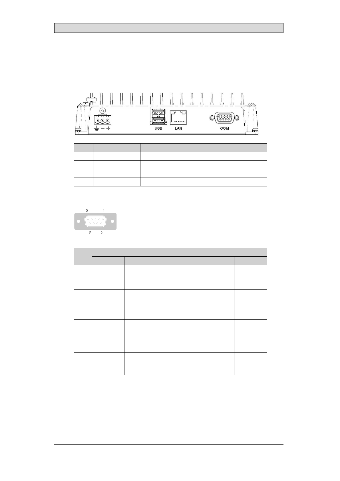
6 OperatorPanelDrawings
6.1 Connectors
Pos. Connector Description
1Powersupply+24VDC
2 USB 2×USBHost2.0,maxoutputcurrent500mA
3 LAN 1×10/100Base-T(shieldedRJ45)
4 COM Serialcommunicationport
6.1.1 CommunicationPorts
Serial connector
Serialport,9-pinfemale
Pin COM1 COM2 COM3 CAN1 CAN2
1- RS-422Tx+
RS-485Tx+/Rx+ -CAN1-H-
2 RS-232RxD - - - -
3RS-232TxD - - - -
4 - RS-422Rx+ RS-485
Tx+/Rx+ -CAN2-H
5 GND GND GND GND GND
6- RS-422Tx-
RS-485Tx-/Rx- -CAN1-L-
7 RS-232RTS - - - -
8RS-232CTS - - - -
9 - RS-422Rx- RS-485
Tx-/Rx- -CAN2-L
The connector supports up to three independent communication channelsand
can be configured for RS-232 and RS-422 or 2xRS-485 or 2x CAN.
BeijerElectronics, MAEN249B 20
Other manuals for X2 control
12
Table of contents
Other Beijer Electronics Marine Equipment manuals


Popular Marine Equipment manuals by other brands


Thrane&Thrane
Thrane&Thrane SAILOR 500 FleetBroadband user manual

E2S
E2S BExDTS110D instruction manual

Furuno
Furuno Navtex NX-700-B Operator's manual

Sealite
Sealite ATLANTIC-3000 Installation & service manual

Simrad
Simrad SX90 - DATASHEET FOR NAVAL AND COAST GUARD REV... quick start guide

JRC
JRC JFC-130 - instruction manual