AUTOHELM ST50 Wind Trim Instruction Manual


16 5T50
WindTrim
and
5peedTrim
Operation
andInstallation
Handbook
ST50
WlndTrlm
and
SpeedTrlm
Operation
and
Installation
Handbook
1
6.
Specification
.
15
-
...
1/
...
1
••'0
5··.
~S
%
10~
1/
...
1
... '0
5··.
~S
oto
10~
,
'15
-:~10
•
Power
Supply
-11
v
to
16v
•
Current
Consumption
-
90ma
(illumination
off)
-
215
ma
(Maximum
illumination)
•
Operating
Temperature
- 0
deg
C
to
+
70
deg
C
•
Size
-
110mm
(4.33in)
x
110mm
(4.33in)
x
24mm
(l
in).
Overall
depth
39mm
(1.5
in)
•
Computer
- 8
bit
Intel
microprocessor
+
8K
Rom
•
Display
-
analogue
+/-15%
-
digital
0-
60
kts
•
Illumination
- 3
levels
and
Off
with
back
lit
display
and
pointer.
...
-:~10
ril
iM
'15
~
rc;3Q
....
'lOLl'.
.
15
-
~i038d
I
81042·1
Autohelm
and
SeaT
alk
are
registered
Trade
Marks
of
Nautech
Limited
Autohelms
policy
of
continuous
improvement
and
updating
may
change
product
specifications
without
prior
notice
Copyright
Nautech
1993

2
ST50
WindTrim
and
SpeedTrim
Operation
and
Installation
Handbook
ST50
WindTrim
and
SpeedTrim
Operation
and
Installation
Handbook
5.2
Locking
on
(ST50
Wind
Trim)
15
To
lock
the
instrument
onto
the
current
displayed
value
simply
press
lock.
This
stores
Apparent
wind
speed
and
direction
and
True
wind
speed
and
direction.
Each
press
of
the
LOCK
button
will
now
cycle
through
the
following
information:
•
Apparent
Wind
speed
•
True
Wind
speed
•
Apparent
Wind
direction
•
True
Wind
direction
Any
variation
from
the
current
and
locked
values
will
be
indicated
on
the
analogue
pointer
as
a
percentage
of
the
locked
value.
The
locked
value
can
be
changed
by
pressing
the
incremenVdecrement
key
until
the
desired
locked
value
is
shown
on
the
display.
Wind
Speed
units
(Knots
or
m/s)
will
be
the
same
as
those
on
the
Main
Wind
instrument.
To
return
to
the
normal
display
press
LOCK
twice
within
1
second.
5.3
Locking
on
(ST50
Speed
Trim)
To
lock
the
instrument
onto
the
current
boat
speed
simply
press
LOCK.
Any
variation
from
the
locked
value
will
be
indicated
on
the
analogue
pointer
as
a
percentage
of
the
locked
value.
The
locked
value
can
be
changed
by
pressing
the
incremenVdecrement
key
until
the
desired
locked
boat
speed
is
shown
on
the
display.
To
return
to
the
normal
display
press
LOCK.

14
5.
Operation
ST50
WindTrim
and
SpeedTrim
Operation
and
Installation
Handbook
ST50
WindTrim
and
SpeedTrim
Operation
and
Installation
Handbook
Contents
3
•
Push
and
hold
down
the
LOCK
button
for
1
second
to
switch
on
(If
off),
or
to
display
the
current
level
of
illumination
(If
already
on)
Control
of
illumination
levels
is
common
to
all
ST50
instrument
modules.
The
control
is
always
selected
using
the
left
hand
push
button
(LOCK).
The
ST50
Wind
Trim
and
Speed
Trim
Instruments
can
only
be
used
when
a
Sea
Talk
compatible
Wind/Speed
Instrument
is
connected
to
the
bus.
Information
from
the
respective
transducers
is
then
is
then
put
onto
the
bus
and
displayed
by
the
Trim
instruments.
F
urther
Trim
instruments
may
be
connected
to
the
bus
to
provide
displays
at
secondary
steering
positions.
5.1 Illumination
[=}~
LOCK
0*
b
[
B.D]
b
Q3
o
o
Pack Contents 5
1. Introduction 6
2. Control Head 6
2.1
Siting
7
2.2
Mounting
procedure
7
Surface
Mounting
7
Bracket
Mounting
8
Flush
Mounting
9
2.3
Power
supply
9
2.4
Connection
to
SeaTalk
compatible
Instruments
/
Autopilot
..
10
2.5
Connection
to
separated
Instruments
10
2.6
Ring
Connection
11
3. Faultfinding
12
4. Maintenance
13
4.1
Display
units
13
4.2
Cabling
13
Advice
13
5. Operation
14
5.1
Illumination
14
5.2
Locking
on
(ST50
Wind
Trim)
15
5.3
Locking
on
(ST50
Speed
Trim)
15
6. Specification
16
•
Push
the
LOCK
button
within
8
seconds
to
select
the
illumination
level
L3
High
L2
Medium
L1
Low
LO
Off
Note:
Display
returns
to
previous
status
after
8
seconds.

4
ST50
WindTrim
and
SpeedTrim
Operation
and
Installation
Handbook
ST50
WindTrim
and
SpeedTrim
Operation
and
Installation
Handbook
4.
Maintenance
4.1
Display
units
13
•
In
certain
conditions,
condensation
may
appear
on
the
window.
This
will
not
harm
the
instrument,
and
can
be
cleared
by
switching
on
the
illumination
to
the
brightest
level.
•
Never
use
any
chemical
or
abrasive
materials
to
clean
your
ST50
Trim
instrument.
If
the
instrument
becomes
dirty
wipe
clean
with
a
damp
cloth.
4.2
Cabling
•
Avoid
running
cables
through
bilge's
where
possible
and
secure
any
coiled
lengths
at
regular
intervals.
•
Avoid
running
cables
close
to
fluorescent
lights,engines,radio
transmitting
equipment
etc.
•
Check
cabling
for
chafing
or
damage
to
outer
casing,
replace
where
necessary
and
re-secure.
Advice
Should
any
difficulties
arise,
please
consult
Nautech's
Product
Support
department
in
the
UK.
or
your
own
National
Distributor
who
will
be
able
to
provide
expert
assistance.

12
3.
Fault
finding
5T5O
WindTrim
and
5peedTrim
Operation
and
Installation
Handbook
5T5O
WindTrim
and
5peedTrim
Operation
and
Installation
Handbook
Pack
Contents
5
All
Autohelm
products
are
subject
to
a
comprehensive
test
procedure
prior
to
packing
and
shipment.
In
the
unlikely
event
that
a
fault
does
arise
the
following
check
list
should
help
cure
the
problem.
The
following
items
are
included
in
the
ST50
WindT
rimjSpeedT
rim
packs.
1.
Power
loom
5.
Fixing
studs
Fault
Digital
and
analogue
display
not
working.
No
exchange
of
information
between
SeaTalk
instruments.
(i.e.
illumination
levels)
Failure
of
a
group
of
instruments
in
the
SeaTalk
chain.
Cause
No
supply.
Action
Check
Cabling
and
security
of
Sea
Talk
connectors.
Return
Instrument
for
repair.
Check
security
of
SeaT
alk
Connectors
0
Remove
instruments
one
by
one
to
isolate
faulty
unit.
Check
security
of
Sea
Talk
Connectors
between
functioning
and
non
functioning
units.
2.
Instrument
head
3.
Protective
cover
4.
Handbook
J
I.
\•••. 0
'.
/
.'
5'I"
5'.
"":'10
10
;'15
15
-
ru
+
lOCK""-
~
/V"
[g)*~
EJ
6.
Fixing
nuts
7.
Dealer
list
8.
Warranty
booklet
Autohelm
WINDTRIM
AND
SPEEDTRIM
Operation
and
Installation
-3
...--------4
r-
5
•'"1""""1"""1".
I§
Autohelm
WORLDWIDE
SERVICE
CENTRES
..
6
2
Autohelm
WARRANTY
TermsandCondlllons
010401

6
ST50
WindTrim
and
SpeedTrim
Operation
and
Installation
Handbook
ST50
WindTrim
and
SpeedTrim
Operation
and
Installation
Handbook
11
1.
Introduction
Congratulations.
You
are
now
the
owner
of
an
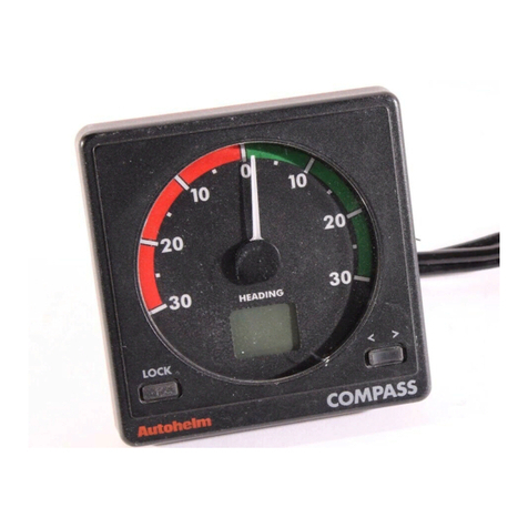
ST50
Trim
instrument.
The
ST50
Wind
trim
and
ST50
Speed
Trim
Instruments
provide
racing
crews
with
up
to
the
second
information
on
changes
in
Wind
Speed
(True
or
apparent)
and
Boat
Speed.
In
addition
the
WindT
rim
can
also
be
used
as
a
steering
indicator
for
wind
direction
(True
or
apparent).
Both
instruments
are
repeaters
and
receive
Speed;Wind
from
the
.Sea
Talk
bus.
Simply
lock
the
instrument
onto
the
current
value
-
shown
on
the
digital
display
-
and
the
analogue
pointer
will
indicate
changes
in
that
figure
of
up
to
+/-15
%.
The
locked
value
can
be
increased
or
decreased
at
any
time
using
the
increment/decrement
button.
SeaTalk
extension
cable
Cat
no.
0131
9m
(30ft)
Junction
box
2.6
Ring
Connection
®
.............--
®
o
(J/~.
®
\J~J
®
;iif--~--)i·l
®
Installations
that
have
a
large
number
of
instruments
on
the
SeaT
alk
bus
may
require
a
second
ring
main
connection.
This
should
be
fed
back
to
the
circuit
breaker
to
avoid
excessive
voltage
drops.
This
can
be
checked
using
the
table
below:
SeaTalk
Cable
length
Up
to
10m
(33ft)
Up
to
20m
(66ft)
Max
number
of
units
(Single
connection)
13
7
Max
number
of
units
(Second
connection)
26
13
The
second
connection
should
be
made
to
the
spare
lead
on
the
last
instrument
and
led
back
to
the
circuit
breaker.
If
the
SeaT
alk
bus
is
receiving
power
from
an
autopilot
course
computer,
the
second
connection
should
be
made
at
the
spare
SeaT
alk
terminal
on
the
course
computer.

10
2.3
Power
supply
5T50
WindTrim
and
5peedTrim
Operation
and
Installation
Handbook
5T5O
WindTrim
and
5peedTrim
Operation
and
Installation
Handbook
2.
Control
Head
7
The
ST50
Speed
;Wind
Trim
Instruments
receive
their
power
from
the
Sea
Talk
bus.
They
can
only
display
Speed;Wind
information
transmitted
on
the
Sea
Talk
bus
by
SeaT
alk
compatible
Speed
and
Wind
Instruments
and
cannot
be
used
as
standalone
instruments.
2.4
Connection
to
SeaTalk
compatible
Instruments
/
Autopilot
All
SeaT
alk
instruments
and
autopilot
control
units
receive
both
power
and
information
from
the
SeaT
alk
bus.
Each
unit
has
two
SeaT
alk
connectors
(3
pin)
on
short
150mm
(6in)
tails
to
allow
adjacent
units
to
simply
plug
together.
e-
M
(Y)
~
E
E
o
......-4
110mm
(4.331n)
---...
(6
[ - J
r-~
Cl
39mm
(l.5in)
24mm
I--I~
Separated
instruments
are
connected
using
one
of
the
SeaT
alk
extension
cables
available.
These
are
supplied
with
a
SeaTalk
connector
fitted
to
each
end.
A
junction
box
is
also
available
to
rejoin
the
cable
if
it
is
cut
to
ease
routing
or
for
shortening.
If
preferred,
any
two
core
screened
cable
to
the
following
specification
may
be
used
in
the
place
of
the
SeaT
alk
cable.
~~II
II
000'00-0
To
course
computer
bus
connection
2.5
Connection
to
separated
Instruments
To
any
further
ST50
instruments
or
autopilot
control
units
2.1
Siting
The
Wind/Speed
Trim
Instrument
is
designed
for
above
or
below
deck
installation.
Position
where
it
is
:
•
Easy
to
read
by
the
helmsman
•
Reasonably
well
protected
from
physical
damage.
•
At
least
230mm
(gin)
from
a
compass.
•
At
least
500
mm
(gin)
from
radio
receiving
equipment.
•
Accessible
from
behind
to
secure
in
place
and
run
cables.
Note:
The
back
cover
is
designed
to
breath
through
a
duct
in
the
cable
boss
to
prevent
moisture
accumulation.
Minimum Copper Area
A.W.G
Screen
2
Cores
O.5mm
O.5mm
22
22

8
ST50
WindTrim
and
SpeedTrim
Operation
and
Installation
Handbook
ST50
WindTrim
and
SpeedTrim
Operation
and
Installation
Handbook
9
2.2
Mounting
procedure
Surface
Mounting
The
surface
must
be
smooth
and
flat.
1.
Use
the
template
provided
to
mark
the
centres
of
the
two
fixing
holes
and
cable
boss.
Note:
Adjacent
units
should
have
6mm
(1/4
in)
separation
to
allow
room
for
the
protective
covers.
2.
Drill
to
4mm
(5/32
in)
diameter.
3.
Use
a
50mm
(2in)
diameter
cutter
to
drill
the
hole
for
the
centre
boss.
4.
Screw
the
two
fixing
studs
(2)
into
the
back
cover.
5.
Pass
the
cable
tails
through
the
central
hole
and
secure
the
instrument
with
the
thumb
nuts
provided
(3).
A
sealing
gasket
(4)
is
already
attached
to
the
back
cover
of
the
instrument.
Bracket
Mounting
As
an
alternative
to
surface
mounting,
a
kit
(Cat
no
D
130)
is
available
to
bracket
mount
the
instrument.
2
Flush
Mounting
A
flush
mounting
kit
(Cat
No.
D
183)
for
installations
where
a
flush
mount
is
required
or
is
more
desireable
.
Full
installation
instructions
are
provided
with
the
kit.
1/
I'.
I4
~y
)f
1'11'1
,2
o
('
,
01117-1
This manual suits for next models
1
Table of contents
Other AUTOHELM Marine Equipment manuals
Popular Marine Equipment manuals by other brands

iXBlue
iXBlue OCTANS NANO quick start guide

Furuno
Furuno FA-30 Setup, installation and troubleshooting tips

Odom
Odom Echotrac CV100 quick start

MORLEY-IAS
MORLEY-IAS MI-BSS-XX-N Installation instructions and information manual

Lewmar
Lewmar V8 Owners installation, operation & servicing manual

Pioneer
Pioneer UD-ME30CP manual