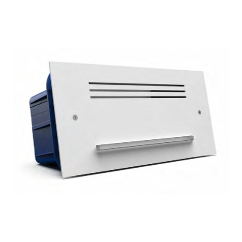
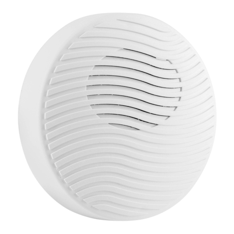
Venitem ONDA User manual

EN
MANUALE TECNICO
TECHNICAL MANUAL
ONDA
IT

MANUALE TECNICO / TECHNICAL MANUAL
2
DESCRIZIONE
Sirena mod. ONDA con lampeggiante a led ad alta luminosità e basso assorbimento – tamper antiapertura e rimozione – sistema
antischiuma e antishock – programmazione suono e temporizzazione – protezione contro inversione di polarità – autocontrollo a
microprocessore di: batteria e speaker con relativa uscita negativa di anomalia – programmazione di polarità comando sirena e ON/
OFF impianto – segnalazione ottica ON-OFF impianto istantanea e permanente – circuito elettronico protetto da inversioni di polarità e
tropicalizzato in resina contro gli agenti atmosferici e l’umidità – coperchio esterno, interno e fondo in metallo.
SCHEMA DI COLLEGAMENTO
CENTRALE ALLARME
TAMPER
TAMPER
USCITA ANOMALIA
BLOCCO SIRENA
STATO IMPIANTO
CONTROLLO SIRENA
+13.8 Vcc
– GND
+21– 43 65 87
1 2 3 4 5
MORSETTI CONNESSIONI
–RIC (1) NEGATIVO ALIMENTAZIONE 0V GND
+RIC (2) POSITIVO ALIMENTAZIONE +13,8V
+C (3) CONTROLLO SIRENA
STI (4) ON/OFF SEGNALAZIONE STATO IMPIANTO
BLS (5) INGRESSO BLOCCO SUONO SIRENA
OUT ANM (6) USCITA ANOMALIA.
OPEN COLLECTOR, 0V = NESSUNA ANOMALIA
TAMPER (7) AUTO-PROTEZIONE E ANTISCHIUMA N.C.
TAMPER (8) AUTO-PROTEZIONE E ANTISCHIUMA N.C.
BLS. BLOCCO SIRENA
Attiva il comando di interruzione suono portando un negativo (0V) al morsetto 5.
USCITA ANOMALIA
La sirena è gestita da un microprocessore in grado di controllare la presenza della ricarica, la batteria, la tromba; in caso di anomalia il
morsetto (6) open-collector si apre.
Il microprocessore esegue automaticamente ogni 4 ore il test di corrente batteria e altri test continuamente. Normalmente, con la sirena
alimentata correttamente l’uscita di anomalia (morsetto 6) rimane a 0V (corrente massima 50mA). In caso di non superamento di
qualsiasi test l’uscita di anomalia si scollega da massa e diventa libera.
Al momento della prima alimentazione della sirena (13,8V o batteria), per facilitare l’installazione,le anomalie si resettano automaticamente
quando la causa scompare. Dopo il primo comando di allarme o ON/OFF le anomalie si resettano solo con un comando al morsetto STI,
+C. Per avviare il test da remoto portare a 12V il morsetto n°4 (STI) per 10 secondi e poi togliere la tensione allo stesso. In questo modo
viene avviato il test che dura 60 secondi. Durante il test la sirena verifica il proprio funzionamento e segnala le eventuali anomalie attraverso
l’uscita anomalia. Per resettare l’anomalia rimuovere la causa dell’anomalia, attendere 10 secondi e portare a 12V il morsetto
n°4 (STI) per almeno 10 secondi. Togliendo brevemente il comando al morsetto +C si resettano tutte le anomalie eccetto quelle
di batteria, solamente dopo 4 ore dal ripristino della batteria la sirena ri-esegue i test e quindi aggiorna anche le anomalie di
batteria.
COMPORTAMENTO CON BASSA TENSIONE
Attenzione: Quando l’alimentazione (ricarica) della sirena è inferiore a 10,5V e la tensione della batteria è inferiore a 9,5V la sirena va in
blocco per evitare falsi allarmi. Appena le tensioni risalgono, la sirena riprende il normale funzionamento.
COLLEGAMENTO TAMPER (ANTIAPERTURA E RIMOZIONE, ANTISCHIUMA E ANTISHOCK)
Collegare ai morsetti n°7 e n°8 la linea tamper proveniente dalla centrale.
DIP-SWITCH
DIP 1 TEMPORIZZAZIONE ALLARME
• Dip-switch 1 in OFF DA FABBRICA il tempo di allarme è di 3 minuti.
• Dip-switch 1 in ON il tempo di allarme è di 8 minuti.
DIP 2 POLARITÀ INGRESSO CONTROLLO SIRENA
N.B.: L’INGRESSO DI DEFAULT È A MANCARE
• Dip-switch 2 in OFF DA FABBRICA il comando per attivare la sirena è positivo.
• Dip-switch 2 in ON il comando per attivare la sirena è negativo.
3
DIP 3 SELEZIONE TONI SIRENA
• Dip-switch 3 in OFF DA FABBRICA il suono è CRESCENTE-CONTINUO-CALANTE.
• Dip-switch 3 in ON il suono è CRESCENTE-CALANTE.
DIP 4 SEGNALAZIONE OTTICA DI STATO IMPIANTO (ON-OFF ISTANTANEO E PERMANENTE) E INGRESSO DI PROVA DA REMOTO
• Dip-switch 4 in OFF DA FABBRICA (Situazione istantanea di ON-OFF)
• Dip-switch 4 in ON (Situazione istantanea di ON-OFF con permanenza del LED destro intermittente per il tempo in cui c’è il comando
al morsetto n°4).
Togliendo il comando tutti i LED rimangono accesi fissi per 5 secondi (OFF) e viene avviato il test completo della sirena, con segnalazione
di eventuali anomalie. Portando un comando al morsetto n°4, tutti i led del lampeggiante eseguono 3 lampeggi (ON). Vengono resettate
le anomalie.
DIP 5 POLARITÀ INGRESSO SEGNALAZIONE OTTICA DI STATO IMPIANTO
N.B.: L’INGRESSO DI DEFAULT È A DARE
• Dip-switch 5 in OFF DA FABBRICA il comando per attivare lo stato impianto è positivo.
• Dip-switch 5 in ON il comando per attivare lo stato impianto è negativo.
MONTAGGIO
1. Fissare la sirena alla parete controllando che il tamper funzioni correttamente;
2. Inserire i cavi di connessione attraverso i fori sul fondo del contenitore;
3. Se necessario, modificare le preimpostazioni di fabbrica impostando i DIP Switch come indicato nel paragrafo precedente;
4. Collegare la batteria e l’alimentazione alla centrale di allarme;
5. Chiudere il coperchio interno ed esterno con le viti fornite;
6. La batteria deve avere una classe di infiammabilità UL94-HB;
7. La fonte di alimentazione deve essere di tipo SELV.
NB: PER EVITARE LA FORMAZIONE DI CONDENSA NELLA SIRENA SI DEVE IMPEDIRE QUALSIASI FLUSSO D’ARIA NELLA CANALINA.
UNA VOLTA PASSATI I CAVI SIGILLARE IL FORO CON DEL SILICONE O UN ALTRO STUCCO. QUESTA OPERAZIONE EVITA CHE, DURANTE
IL PERIODO INVERNALE, L’ARIA CALDA E UMIDA CHE ESCE DALL’EDIFICIO ATTRAVERSO IL PASSAGGIO VADA A FORMARE CONDENSA
NELLA SIRENA PRECLUDENDO IL CORRETTO FUNZIONAMENTO DI QUESTA.
CARATTERISTICHE TECNICHE
Tensione
Nominale di Alimentazione 13,8 Vdc
Comando +C (3) minimo 4,5 Vdc
Alimentazione minima 10,5 Vdc
Alimentazione massima 15,5 Vdc
Corrente
Assorbimento suono dalla batteria 1,3 A +100/-300 mA
Max da centrale 700 mA ± 100 mA
Assorbimento lampeggiante 25 mA ± 10 mA
A riposo 15mA
Dagli ingressi di controllo +0,5 mA @Vc=12V; -0,3 mA @Vc=0V
Open collector -50 mA Max
Frequenza fondamentale 2100 Hz
Potenza sonora 106 dB a 1 m
Durata lampeggiante LED 1.000.000 lampeggi
Grado di protezione IP 44
Classe ambientale IV (all’esterno)
Condizioni ambientali esterne Da –25° a +55° C
Temporizzazione Programmabile vedi DIP-SWITCH
Comando della centrale 2 o 3 fili
Dimensioni sirena 226x306x78 (H x L x P)
Peso 2.800 gr.

MANUALE TECNICO / TECHNICAL MANUAL
4
1517906067
MANUALE CIRCUITO RGBW
DESCRIZIONE
Il circuito di controllo del LED RGBW permette il controllo del LED in base alle
proprie esigenze. I DIP-SWITCH permettono di scegliere la priorità del colore e il
lampeggio in sequenza.
DIP-SWITCH
DIP-SWITCH FUNZIONE SETTAGGIO
1POLARITÀ INGRESSI A,B,C,D OFF: Negativo (0V)
ON: Positivo (+12V)
2-3 FUNZIONAMENTO INGRESSI
2 OFF - 3 OFF:
2 OFF - 3 ON:
2 ON - 3 OFF:
Priorità ingresso nell’ordine (A-1, B-2, C-3, D-4)
L’ultimo ingresso arrivato ha la precedenza
Lampeggiante o rotazione colori
4 NON USATO –
MORSETTIERA
+12 POSITIVO USCITA ALIMENTAZIONE
GND NEGATIVO USCITA ALIMENTAZIONE
A INGRESSO LED ROSSO
BINGRESSO LED VERDE
C INGRESSO LED BLU
D INGRESSO LED BIANCO
MADE IN ITALY
GARANZIA
Tutti i prodotti Venitem sono garantiti contro i difetti di fabbricazione o di
materiale. Nell’intento di migliorare il design e la qualità dei propri prodotti
la ditta Venitem si riserva di modificare il prodotto senza alcun preavviso.
Tutti i prodotti guasti o difettosi vanno resi al proprio fornitore.
LED SINISTRO (J2)
SCHEDA SIRENA (J1)
DIP-SWITCH
CONNETTORI LED RGBW (J5)
1 2 3 4
ON
J1
+12
GND
A
B
C
D
SW1
J2
J5
USCITA +12V E GND
ROSSO
VERDE
BLU
BIANCO

5
DESCRIPTION
Sounder mod. ONDA with high luminosity and low consumption LED flashing light – anti-opening and anti-removal tamper protection
– anti-foam anti-shock system – programmable sound and timing – protected against polarity inversion – microprocessor self-test of:
battery and speaker with anomaly negative output - programming of sounder polarity command and system ON/OFF – immediate or
permanent optical indication of ON/OFF system – electronic circuit protected against polarity inversion and resin tropicalization against bad
weather conditions and humidity – external cover, internal cover and bottom in metal.
CONNECTION SCHEME
CONTROL PANEL
TAMPER
TAMPER
ANOMALY OUTPUT
BLOCK SPEAKER
SYSTEM STATUS
SOUNDER CONTROL
+13.8 Vcc
– GND
+21– 43 65 87
1 2 3 4 5
TERMINALS CONNECTIONS
–RIC (1) NEGATIVE POWER SUPPLY OV GND
+RIC (2) POSITIVE POWER SUPPLY +13,8V
+C (3) SOUNDER CONTROL
STI (4) ON/OFF - ALARM SYSTEM STATUS NOTICE
BLS (5) INPUT FOR SOUND INTERRUPTION
OUT ANM (6) ANOMALY OUTPUT. OPEN COLLECTOR
0V = NO ANOMALY
TAMPER (7) N.C. SELF-PROTECTION AND ANTI-FOAM
TAMPER (8) N.C. SELF-PROTECTION AND ANTI-FOAM
BLS. SOUND BLOCK
It activates the sound interruption by giving a negative signal (0V) to terminal 5.
ANOMALY OUTPUT
The sounder is managed by a microcontroller able to check battery recharge, battery status and the speaker; in case of anomaly, open
collector terminal (6) opens.
Every 4 hours, the microcontroller automatically performs the battery test. Moreover, other tests are carried out continuously. If the sounder
is correctly powered, the anomaly output (terminal no. 6) usually stays at 0V (current max 50mA). In case a test performed is not passed,
the anomaly output disconnects from ground and becomes free.
At the first sounder powering (13.8V or battery), to enable an easier installation, all anomalies are automatically reset to zero when the
cause disappears. After the first alarm or ON/OFF trigger, anomalies are reset to zero only if a command is given to terminal STI or +C. To
launch the remote test, take terminal no. 4 (STI) to +12V for 10 seconds and then take voltage away from the terminal. This procedure
launches the test lasting 60 seconds. During the test, the sounder controls how it is working and notifies any anomaly through the anomaly
output. To reset anomalies to zero, remove the anomaly cause first, then wait for 10 seconds and then take terminal no. 4 (STI)
to 12V for at least 10 seconds. Taking away the command from terminal +C for a short time, all anomalies are reset to zero with
the exception of the anomalies concerning the battery. After 4 hours from battery restoration, the sounder performs again the
tests thus updating battery anomalies too.
LOW VOLTAGE SITUATION
Attention: when the sounder power supply (recharge) is lower than 10.5V and the battery voltage is lower than 9.5V, the sounder goes into
lock mode to avoid false alarms. As soon as the voltages go up, the sounder starts again to work normally.
TAMPER CONNECTION (ANTI-OPENING AND ANTI-REMOVAL, ANTI-FOAM AND ANTI-SHOCK)
Connect terminals no. 7 and no. 8 to the tamper line coming from the control panel.
DIP-SWITCHES
DIP 1 SOUND TIMING
• Dip-switch 1 in OFF: sound timing is 3 minutes (DEFAULT SETTING).
• Dip-switch 1 in ON: sound timing is 8 minutes.
DIP 2 SOUNDER CONTROL INPUT POLARITY
NOTE: THE INPUT IS MISSING BY DEFAULT
• Dip-switch 2 in OFF: trigger for sounder activation is positive (DEFAULT SETTING).
• Dip-switch 2 in ON: trigger for sounder activation is negative.

MANUALE TECNICO / TECHNICAL MANUAL
6
DIP 3 SOUND TYPE SELECTION
• Dip-switch 3 in OFF: sound is INCREASING-CONTINUOUS-DECREASING (DEFAULT SETTING).
• Dip-switch 3 in ON: sound is INCREASING-DECREASING.
DIP 4 SYSTEM STATUS OPTICAL SIGNALISATION (ON-OFF IMMEDIATE AND PERMANENT) AND REMOTE TEST INPUT
• Dip-switch 4 in OFF: instantaneous ON-OFF situation (DEFAULT SETTING)
• Dip-switch 4 in ON: instantaneous ON-OFF situation with right LED flashing intermittently while trigger is given to terminal 4.
By taking command away, all LEDs stay ON for 5 seconds (OFF) and the complete sounder test is launched, with signalization of any
anomalies. By giving a command to terminal 4, all LEDs of the flashing light blink 3 times (ON). All anomalies are reset to zero.
DIP 5 INPUT POLARITY OF SYSTEM STATUS OPTICAL SIGNALIZATION
NOTE: DEFAULT INPUT IS GIVING
• Dip-switch 5 in OFF: trigger for system status activation is positive (DEFAULT SETTING).
• Dip-switch 5 in ON: trigger for system status activation is negative.
MOUNTING
1. Screw the sounder on the wall and check if the tamper works properly;
2. Insert the connection cables through the holes located on the sounder base;
3. If necessary, modify the default settings acting on the DIP-SWITCHES as indicated above;
4. Connect the battery and the power supply to the control panel;
5. Close both internal and external covers using the screws provided;
6. Battery must have UL94-HB flammability rate;
7. Power supply must be of SELV type.
ATTENTION: NOT TO HAVE CONDENSATION IN THE SOUNDER, IT IS IMPORTANT TO AVOID ANY AIR FLOW INSIDE THE DUCT.
TO SUCH PURPOSE, ONCE THE SOUNDER IS CONNECTED, SEAL THE HOLE USING SOME SILICON OR ANY OTHER PLASTER.
THIS OPERATION PREVENTS CONDENSATION FROM FORMING INSIDE THE SOUNDER; CONDENSATION MOSTLY APPEARS
IN WINTER AND IT IS USUALLY CAUSED BY WARM AND HUMID AIR COMING OUT OF THE WALL WHERE THE SOUNDER IS
INSTALLED AND PASSING THROUGH THE HOLE LOCATED ON THE SOUNDER BASE.
TECHNICAL FEATURES
Voltage
Rated power supply voltage 13.8 Vdc
Minimum command +C (3) 4.5 Vdc
Minimum power supply 10.5 Vdc
Maximum power supply 15.5 Vdc
Current
Sound consumption from battery 1.3 A +100/-300 mA
Max from control panel 700 mA ± 100 mA
Flashing unit consumption 25 mA ± 10 mA
Consumption in stand-by 15mA
Consumption from control inputs +0.5 mA @Vc=12V; -0.3 mA @Vc=0V
Open collector -50 mA Max
Fundamental frequency 2100 Hz
Sound pressure 106 dB @ 1m
LED flashing unit life 1.000.000 flashes
Protection degree IP 44
Environmental class IV (outdoor)
Working temperature conditions From –25° to +55° C
Timing Settable according to chart
Control panel command 2 or 3 wires
Size 226x306x78 (H x L x W)
Weight 2.800 gr.

7
RGBW CIRCUIT MANUAL
DESCRIPTION
LED RGBW circuit allows LED control according to the needs. The DIP-SWITCHES
allow to choose the colour priority and the flashing sequence.
DIP-SWITCHS
DIP-SWITCHS FUNCTION SETTING
1 A,B,C,D INPUTS POLARITY OFF: Negativo (0V)
ON: Positivo (+12V)
2-3 INPUTS FUNCTIONING
2 OFF - 3 OFF:
2 OFF - 3 ON:
2 ON - 3 OFF:
Input priority in sequence (A-1, B-2, C-3, D-4)
Last input come has the priority
Flashing or rotating colors
4 NOT USED –
TERMINALS
+12 POSITIVE POWER SUPPLY
GND NEGATIVE POWER SUPPLY
A RED LED INPUT
B GREEN LED INPUT
C BLUE LED INPUT
D WHITE LED INPUT
LEFT LED (J2)
SOUNDER BOARD (J1)
DIP-SWITCHS
RGBW LED CONNECTORS (J5)
1 2 3 4
ON
J1
+12
GND
A
B
C
D
SW1
J2
J5
+12V OUTPUT AND GND
RED
GREEN
BLUE
WHITE
MADE IN ITALY
WARRANTY
All Venitem products are granted against factory or material defects. In
order to improve design and quality of the products, Venitem reserves the
right to modify them without prior notice. All faulty or defective items must
be returned to the supplier.

Sede legale e operativa:
Via del Lavoro, 10 30030 Salzano (VE) - Italy
Tel. +39.041.5740374 - Fax +39.041.5740388
UNI EN ISO 14001 UNI EN ISO 9001
AZIENDA CERTIFICATA
MA-SE-ONDA-00-02
Other manuals for ONDA
1
Table of contents
Languages:
Other Venitem Marine Equipment manuals

Venitem
Venitem HEMA L User manual

Venitem
Venitem RIO L User manual

Venitem
Venitem GIUDECCA User manual

Venitem
Venitem MINI MARINA L User manual

Venitem
Venitem SP200 User manual

Venitem
Venitem DOGE EV12 User manual

Venitem
Venitem MINI DOGE User manual

Venitem
Venitem DOGE AS1 User manual

Venitem
Venitem RIALTO L Guide

Venitem
Venitem TRIADE F24 User manual