BEING L Series Operating instructions


BEING Instrument Inc.
1.0 INTRODUCTION
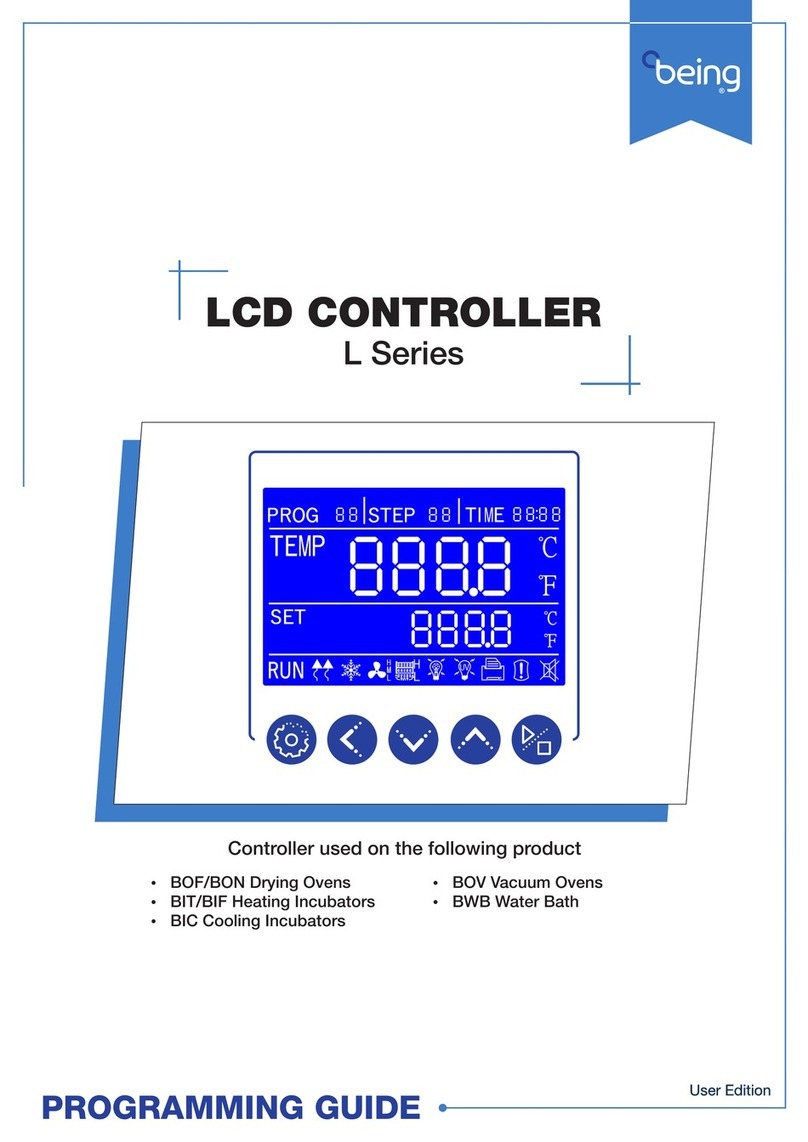
This programming guide provides the user of the following BEING laboratory instruments the
ability to change the backlit LCD controller’s internal parameters to allow the instrument to
work more eectively and eciently for your operation, process, or experiment.
BIF-16, -35, -55, -120, -200, -400
Mechanical Convention Incubators
BIT-16, -35, -55, -120, -200
Natural Convention Incubators
BIC-60, -120, -250
Cooling incubators
BOF-30, -50, -120, -200, -400
Mechanical Convention Drying Ovens
BON-30, -50, -115, -200
Natural Convention Drying Ovens
BOV-20, -50, -90
Vacuum Ovens
BWB-05, -12, -22
General Purpose Water Bath
2.0 TABLE OF CONTENTS
Safety messages ..................................................................................................................................................................................... 03
Controller elements overview .......................................................................................................................................................... 04
Changing temperature unit of measurement............................................................................................................................. 05
Calibration after unit of measurement change .................................................................................................................... 06-07
What is a multi-step program ..................................................................................................................................................... 08-09
Turn on/o multi-step programs .....................................................................................................................................................10
Programming multi-step programs ................................................................................................................................................ 11
Selecting multi-step program to run .............................................................................................................................................. 12
Setting up program cycling ...............................................................................................................................................................13
Setting up RUN delay — xed value (single-step) programs ................................................................................................ 14
Setting up RUN delay — multi-step programs ........................................................................................................................... 14
Changing power-up mode ................................................................................................................................................................. 15
Internal parameters overview..................................................................................................................................................... 16-17
02

BEING Instrument Inc. 03
Safety Messages
Safety Message
Be sure that you are completely familiar with the safe operation of each BEING series.This unit may be connected to other machinery, such as a vacuum pump. Improper use can cause serious or fatal
injury.
Installation and repair procedures require specialized skills with laboratory equipment and electricity. Any person that installs or repairs this unit must have these specialized skills to ensure that this
unit is safe to operate. Contact BEING Instrument, Inc. or their local authorized distributor for repairs or any questions you may have about this unit’s safe installation and operation.
The precaution statements are general guidelines for the safe use and operation of these instruments. It is not practical to list all unsafe conditions.Therefore, if you use a procedure that is not recom-
mended in this programming guide, you must determine if it is safe for the operator and all personnel in the proximity to the instrument. If there is any question of the safety of a procedure, please
contact BEING Instrument before starting or stopping the instrument.
This equipment contains high voltages. Electrical shock can cause serious or fatal injury. Only qualied personnel should attempt the startup procedure or troubleshoot this unit.
• Documentation must be available to anyone that operates this equipment at all times.
• Keep non-qualied personnel at a safe distance from this unit.
• Only qualied personnel familiar with the safe installation, operation, and maintenance of this unit should attempt startup or operating procedures.
• Always stop the instrument before making or removing any connections.
Symbols used in this Programming Guide
The following signal word panels, safety symbols, and non-safety symbols are used to alert you to potential personal injury hazards or information of importance. Obey all safety messages that
follow these symbols to avoid possible personal injury or death.
• Signal word panels
Signal word panels are a method for calling attention to a safety messages or property damage messages and designate a degree or level of hazard
seriousness. It consists of three elements: a safety alert symbol, a signal word and a contrasting rectangular background. The following signal word
panels are in accordance with ANSI Z535.4-2111 (R2017) and ISO 3864 standards.
Indicates a hazardous situation which, if not avoided, may result in minor or moderate injury.
• Safety symbols
Safety symbols are graphic representations—of a hazard, a hazardous situation, a precaution to avoid a hazard, a result of not avoiding a hazard, or any
combination of these messages—intended to convey a message without the use of words.The following safety symbols are used in this quick start guide.
Mandatory Warning
General alert. Mandatory action. Safety Alert Symbol. General caution.
Hot Surface
Prohibition
Do not touch uid.
Wear protective gloves.

BEING Instrument Inc.
04
PROG Area: Displays the program working or setting group. Controller
is capable of programming and storing up to 7 programs.
STEP Area: Displays the number of the step within a program. There
are 9 steps available for each program.
TIME Area: Displays the running time or parameter value.
TEMP Area: Displays the measured (actual) temperature within the
unit’s chamber. Also, displays the ambient room temperature when
requested.
SET Area: Displays the temperature setpoint.
RUN: Illuminates when the unit’s program is working. Turns o when
program is stopped.
HEAT: Arrows illuminate and blinks when the unit’s heater is on.
Turns o when heating elements are o.
COOLING: Snowake illuminates and blinks when the unit’s cooling
is on. Turns o when cooling system is o. Series BIC only.
FAN: Fan blades illuminate and blinks when the unit’s circulation fan
is on. H (high), M (medium), and L (low) indicate the fan speed. Turns
o when fan is o. Series BIF, BIC, and BOF only.
Water Level: Indicates high and low water bath levels.
Visible Alarm: Illuminates when the program has completed, has
been stopped by user, or when an over temperature condition
occurs. Additionally, when the visible alarm illuminates an audible
alarm will start.
Audible Alarm Disabled: Illuminates when the user presses any key
or when the unit’s power is turned o.
Keys
SETTING: Starts the programming of the temperature and run time.
Accepts the temperature and run time values.
Shift: For changing the parameter value being set and viewing
ambient temperature.
Decrease: Used for setting parameter value, modication of various
values, or start/stop auto-tuning.
Increase: Used for setting parameter value, or press and hold for
more than 2 seconds to view the remaining program time.
RUN/STOP: Press for 2 seconds to run or stop the controller.
Controller Element Overview

BEING Instrument Inc.
STEP 1: Enter Level 3 of controller internal parameters.
Press and hold the SETTING and shift keys for 3 seconds to enter
the controller’s internal parameter settings.
Time area will change and rst digit will blink.
Temperature setpoint must be changed manually.
Units are shipped with temperature measurement set to Celsius (OC).
Parameter CF=0000.
05
Changing Temperature Unit of Measurement
STEP 2: Enter Level 3 code LK=0088.
STEP 3: Scroll to parameter CF.
STEP 4: Change parameter CF.
STEP 5: Set parameter and return to standard state.
Press the increase key to enter the rst code digit. Press the shift
key to move to the second code digit. Digit will blink. Press the
increase key to enter the second code digit.
Press the SETTING key to enter the Level 3 controller parameters.
First available parameter will appear.
Press the SETTING key 15 time to scroll through parameters until
the parameter CF appears.
Press the increase or decrease key to change the rst digit.
CF=0000 Celsius (OC)
CF=0001 Fahrenheit (OF)
Press the SETTING key 2 times to set parameter CF and return to
standard state.
Upon changing the temperature unit of measurement, the
actual temperature will change its value.

BEING Instrument Inc.
06
Calibration After Unit of Measurement Change
Check the instrument’s chamber temperature after changing
the unit of measurement to ensure the controller is measuring
it accurately.
Tools Needed:
A remote-monitoring thermocouple thermometer with a
NIST-traceable calibration certicate.
Series BIF, BIT, BOF, and BON
STEP 1: Place test materials in chamber, set program, and
press run for 3 seconds.
Compare the thermometer’s and probe’s temperature ratings against the
series operating range to ensure compatibility.
Series BOV: A ribbon lead thermocouple is required so as not to damage
the door seal. Additionally, the lead’s and probe’s materials must be rated for
temperatures up to ambient + 200OC (ambient + 392OF).
STEP 2: Insert thermometer probe into test hole.
Upon reaching the set temperature, insert thermometer probe
into the test hole.
STEP 4: Compare thermometer readings to set and present
temperatures. If SV1≠PV1≠TV1 or SV2≠PV2≠TV2, move
to STEP 5.
Make sure thermometer is stable. Then record the set temperature (SV1 &
SV2), present value (PV1 & PV2), and thermometer reading (TV1 & TV2).
STEP 3: Run test again at a second set temperature (SV2) at
least 10OC (18OF) greater than the rst.
Series BOV
STEP 1: Place test materials in chamber. Place temperature
probe in the center of the chamber. Close and lock
door. Set program and press run for 3 seconds.
STEP 3: Compare thermometer readings to set and present
temperatures. If SV1≠PV1≠TV1 or SV2≠PV2≠TV2, move
to STEP 4.
Make sure thermometer is stable. Then record the set temperature (SV1 &
SV2), present value (PV1 & PV2), and thermometer reading (TV1 & TV2).
STEP 2: Run test again at a second set temperature (SV2) at
least 10OC (18OF) greater than the rst.
Series BIC
STEP 1: Place test materials in chamber, set program, and
press run for 3 seconds.
STEP 2: Open test hole.
Upon reaching the set temperature, insert thermometer probe into the
test hole.
STEP 5: Compare thermometer readings to set and present
temperatures. If SV1≠PV1≠TV1 or SV2≠PV2≠TV2, move
to STEP 6.
Make sure thermometer is stable. Then record the set temperature (SV1 &
SV2), present value (PV1 & PV2), and thermometer reading (TV1 & TV2).
STEP 4: Run test again at a second set temperature (SV2) at
least 10OC (18OF) greater than the rst.
Thermometer probe’s outer diameter must be less than 8mm.
STEP 3: Insert thermometer probe into test hole.
The test hole is Ø25mm and located on the right
side of the oven.

BEING Instrument Inc. 07
Series BWB
STEP 1: Fill chamber. Place test materials in chamber. Close
chamber cover. Set program and press run for
3 seconds.
STEP 4: Compare thermometer readings to set and present
temperatures. If SV1≠PV1≠TV1 or SV2≠PV2≠TV2, move
to STEP 5.
Make sure thermometer is stable. Then record the set temperature (SV1 &
SV2), present value (PV1 & PV2), and thermometer reading (TV1 & TV2).
STEP 3: Run test again at a second set temperature (SV2) at
least 10OC (18OF) greater than the rst.
STEP 2: Upon reaching set temperature, open chamber cover.
Insert the thermometer probe into the center of bath.
The Math
STEP 4/5/6: Perform the following calculations to determine
Pb and PK.
Full Scale Adjustment (Slope)
PK={[((TV2-TV1))/((SV2-SV1))]-1}x 4000
Zero Adjustment (Intercept)
Pb=TV2-{[PK/(4000/SV2)]+SV2

BEING Instrument Inc.
08
What is a Multi-step Program

BEING Instrument Inc. 09

BEING Instrument Inc.
10
Turning On/O Multi-step Programs
STEP 1: Enter Level 4 of controller internal parameters
Press the SETTING and SHIFT keys for 3 seconds to enter the
controller’s internal parameter settings.
Time area will change and rst digit will blink.
Upon initializing the unit for the rst time, user needs to set the temperature
and time for each step in a program.
Units are shipped with the controller set to xed value (single-step)
programs. Parameter Mo=0000.
STEP 2: Enter Level 4 code. LK=8286
STEP 3: Change parameter Mo
STEP 4: Set parameter and return to standard state
Press the INCREASE key to enter the rst code digit. Press the
SHIFT key to move to the second code digit. Digit will blink. Press
the INCREASE key to enter the second code digit.
Follow the same procedure for the third and fourth code digits.
Press the SETTING key to enter the Level 4 controller parameters.
The Mo parameter will appear.
Press the INCREASE or DECREASE key to change the rst digit.
Mo=0000 Fixed value (Single-step) program
Mo=0001 Multi-step programs
Press the SETTING key 1 time to set parameter Mo and return to
standard state.
Upon changing to multi-step progams, the controller screen will
change to PROG 1.

BEING Instrument Inc. 11
Programming Multi-step Programs
STEP 1: Select program number to set up
Press the INCREASE key to select the program number
to program.
STEP 2: Set the STEP temperature
STEP 3: Set the STEP run time
Press the INCREASE or DECREASE key to enter the
tenths temperature value.
Press the SETTING key to accept the run time.
The next program step will appear. The tens
temperature value will blink.
Upon setting all of the steps, the controller will return to multi-
step program standard state.
Press the SETTING key to accept temperature
setpoint.The rstTIME digit will blink.
Units are shipped with the controller initially set to PROG 1 when multi-
step programs are turned on. If multi-step programs are turned o and
later turned on, the last program run or selected will be displayed.
Press the SETTING key for 3 seconds.The“PROG 1”will initially
blink. Then the number will blink.
Units are shipped with all steps in each program set to zero temperature and
zero run time.
Pressing the SETTING key starts the
programming process.
STEP 1 will appear. “End”in TIME area will
change to run time digits. PROG and the tenths
temperature value blinks.
Press the SHIFT key to move to the next parameter
digits. Each move will cause parameter to blink.
Use INCREASE or DECREASE key to set each
temperature value.
Use INCREASE or DECREASE key to set each
minute and hour value.
Press the SHIFT key to move to the next
parameter digits.
STEP 4: Repeat Steps 2 and 3 for each program step
Leave step temperature and run time at zero for each step not needed for the
program.

BEING Instrument Inc.
12
Selecting Multi-step Program to Run
STEP 1: Press SETTING key
Units are shipped with the controller initially set to PROG 1 when multi-
step programs are turned on. If multi-step programs are turned o and
later turned on, the last program run or selected will be displayed.
Press the SETTING key one (1) time. The“PROG”area will blink.
STEP 2: Select program number
Press the INCREASE or DECREASE to select
program number.
Press the SETTING key to conrm the program to be run.
Pressing the RUN key for 2 seconds starts the program. STEP
area, RUN, HEAT, and run time illuminate.
STEP 3: Press RUN key

BEING Instrument Inc. 13
Setting up Program Cycling
STEP 1: Ensure the multi-step program function is turned on.
See “Turning On/O Multi-step Programs” instructions on page 06.
Units are shipped with program cycling set to 1. Parameter Cy=0001.
This function is for multi-step programs only.
Press the SETTING and SHIFT keys for 3 seconds to enter the
controller’s internal parameter settings.Time area will change
and rst digit will blink.
STEP 2: Press SETTING key
STEP 3: Scroll to parameter Cy
Press the SETTING key to enter Level 1 parameters.
Press the INCRREASE key to enter the rst cycle value.
Press the SHIFT key to move to the second code digit.
Digit will blink. Press the INCREASE key to enter the
second cycle value.
Press the SETTING key 1 time to scroll through
parameters until the parameter Cy appears.
STEP 2: Select program (1 - 8) to run multiple cycles.
See “Selecting Multi-step Program to Run” instructions on page 08.
STEP 3: Enter Level 1 of controller internal parameters
When entering the controller’s internal parameters, Level 1, LK =0000,
will always come up rst.
Parameter Cy=0001 to 0099.
STEP 4: Set parameter and return to multi-step program
standard state
Press the SETTING key 2 times to set parameter Cy and return to
multi-step program standard state.

BEING Instrument Inc.
14
Setting up RUN Delay
Fixed Value (Single-step) Programs
Multi-step Programs

BEING Instrument Inc. 15
Changing Power-up Mode

BEING Instrument Inc.
16
PROMPT INITIAL VALUEFUNCTION NAME FUNCTION RANGE EXPLANATION
Pn Working Group 0 – 8 For multi-step program control only, set up a working group for instrument operation.When Pn is set
to 0, group 0 is xed value (single-step) control.
Cy 0001No. of Cycles 0 – 99
Controls number of times a multi-step program runs. When Cy is 0, the instrument has been running
between the work groups. When Cy IS NOT 0, the instrument will automatically stop after cycling Cy
times in the work group. The value will automatically return to 1 after shutdown.
dy 00:00Run Delay 00:00 – 99:59 (hh:mm) 00:00 - No delay. Other values - Start of a program will be delayed dy time after pressing the RUN key.
Level 1
LK [ ] = 0000
PROMPT INITIAL VALUEFUNCTION NAME FUNCTION RANGE EXPLANATION
tM 200.0
Maximum Allowable
Temperature Setting
Set within the
measuring range Stop heating and alarm when the maximum temperature is exceeded
Po 0002Power-up Mode 0 – 2
Po=0000: Controller is in a stopped state after power-on. User must start the operation by pressing
the RUN/STOP button for 3 seconds. Po=0001: Controller automatically starts the step operation after
power-on. Po=0002: Controller starts running from the last power-o.
AL 003.0Alarm Setting 0 – Full Range Alarm illuminates with audible output (and HOLD function) when the temperature exceeds the
Setpoint+AL value.
Pb 000.0Zero Adjustment (Intercept) -100.0 – 100.0 When the zero error of the meter is large and the full-scale error is small, adjust this value. Generally,
PT100 rarely adjusts this value.
PK 0000Full Scale Adjustment (Slope) -1000 – 1000 When the zero error of the meter is small and the full-scale error is large, adjust the value. PK=4000 x
(mercury thermometer value-display value)/display value, generally PT100 rst adjust this value.
PA 000.0
Ambient Temperature Correction -80 – 80 When there is an error between the actual ambient temperature and the controller display ambient
temperature, adjust the value
Level 2
LK [ ] = 0003
Internal Parameter Settings Overview
Press increase key to change rst digit
value.Value will blink as it is being set.
Press the shift key to move to the next
parameter digits. Each move will cause
digit to blink.
Press and hold SETTING and shift keys
for 3 seconds to view the controller’s
internal parameters.
Press SETTING key once entering
required code for the parameter
level you want to change.
First available function parameter within
level will appear. Press increase key to
change rst digit value.Value will blink as
it is being set.
Press the shift key to move to the next
parameter digits. Each move will cause
digit to blink.
Press SETTING key once entering
parameter value.
Next parameter will appear or
controller will return to standard
state.
STEP 1 STEP 2 STEP 3 STEP 4 STEP 5
Changing parameter value process

BEING Instrument Inc.
PROMPT INITIAL VALUEFUNCTION NAME FUNCTION RANGE EXPLANATION
Mo 0000ProgramType Selection 0 – 1 Mo=0000: FixedValue (Single-step Program)
Mo=0001: Multi-step Program
PROMPT INITIAL VALUEFUNCTION NAME FUNCTION RANGE EXPLANATION
CL 000.5Cooling Control Set Up -5.0 – 60.0
When the compressor is started and stopped for cooling, when the temperature exceeds the CL value
and the compressor cooling control delay is met, the cooling light is on, the cooling contact is turned
on, and the compressor is started.
dr 0001
Gating Options 0 – 2 dr=0000: No gating dr=0001: Close the door dr=0002: Open the door
CF 0000
Unit of
Temperature Measurement 0 – 1 CF=0000: Celsius
CF=0001: Fahrenheit
co 0001
Cooling Options 0 – 2 co=0000: RUN/Stop type co=0001: Balanced type, related to ambient temperature
co=0002: Balanced type, related to CL
Ct 0001Cooling Control Delay 0 – 300 seconds The delay time required to start the compressor twice, Ct=0 cancels the compressor function.
LA 010.0
Lower Limit
Absolute Value Alarm Full Range Alarm illuminates with audible output when the measured temperature is lower than this value.
P 015.0Proportional Band 2.0 – 300.0 Proportional eect adjustment, the greater the P, the smaller the proportional eect, the lower the
system gain.
I 0300IntegralTime 2 – 3600 seconds Integral action time constant, the greater the I, the weaker the integral action.
d 0300DerivativeTime 0 – 3600 seconds Derivative action time constant, the greater the d, the stronger the derivative action.
Hp 0100Overshoot Suspression 0 – 100% Controller has stronger ability to suppress temperature overshoot when the value of Ar is smaller.
SL 050.0Segmentation Point 0.0 – 300.0 Sectional setting temperature of section PID.
Lr 0020Overshoot Suppression 1 0 – 100 Lr overshoot suppression eect when set temperature is less than or equal to SL.
t 0003Heating Cycle 1 – 100 seconds Relay output <20s, SSR and thyristor switch <3s.
Lt 000.0
Temperature Lower
Limit Setting -80.0 – 320.0 Set the lower limit of measurement temperature.
Ht 300.0
Temperature Upper
Limit Setting -80.0 – 320.0 Set the upper limit of measurement temperature.
md 0000Circulation Fan Selection 0 – 1 md=0000: Automatic circulation fan
md=0001: Manual circulation fan
Fn 002.0Fan Speed Conversion Value 0 – 300.0
• When the measured temperature is greater than the set temperature +Fn or when the measured
temperature is less than the set temperature -Fn, the high-speed fan starts.
• When the measured temperature is higher than the set temperature -Fn and the measured temperature
is lower than the set temperature +Fn, the low-speed fan start.
• This parameter is only valid when the circulating fan parameter md is selected as 0. Fn=0, no fan
output; Fn=300.0, rst gear fan output.
17
Level 3
LK [ ] = 0088
Level 4
LK [ ] = 8286

Other manuals for L Series
1
Table of contents
Other BEING Controllers manuals
Popular Controllers manuals by other brands
Analog Devices
Analog Devices AN-877 Application note
FNW
FNW ASD Series Installation, operation & maintenance instructions
Honeywell
Honeywell HPMOM6CB installation instructions
HID
HID Aero X1100 installation guide
TJERNLUND
TJERNLUND 950-8804 UC1 UNIVERSAL CONTROL BOARD KIT (VERSION X.04) 8505017 REV A... manual
Honeywell Home
Honeywell Home HVC0001 owner's guide
