HID Aero X1100 User manual

HID Aero™ X1100
Intelligent Controller
Up to 4 Readers, 7 Inputs, 4 Outputs PLT-04233, Rev. A.3
© 2019 - 2020 HID Global Corporation/ASSA ABLOY AB. All rights reserved. HID, the HID Brick logo, the Chain Design, HID Aero, and HID Signo are trademarks or registered
trademarks of HID Global, ASSA ABLOY AB, or its aliate(s) in the US and other countries and may not be used without permission. All other trademarks, service marks, and
product or service names are trademarks or registered trademarks of their respective owners.
hidglobal.com An ASSA ABLOY Group brand
INSTALLATION GUIDE
Supplied parts
HID Aero X1100 Intelligent Controller (1)
Installation guide (1)
Mounting screws (4) 0.138" × 1" (3.5 mm × 25 mm)
Casing screws (4) 0.118" × 0.75” (3 mm × 20 mm)
Recommended parts
(not supplied)
Certified DC power supply
Drill with various bits for mounting hardware
For DIN rail mounting: Brackets (2) - Phoenix Contact,
USA 10 Series Rail Adapter, part number 1201578.
Screws (4) - Self tapping, countersunk,
3.0 mm × 10 mm (or 3.0 mm × 8 mm)
X1100 Overview
The X1100 performs intelligent access control operations, input monitoring and output control for up to:
64 readers, 64 doors, 615 inputs, 388 outputs.
CABLE REQUIREMENTS (NOT SUPPLIED)
Host–Ethernet CAT-5, 328 ft (100 m)
Readers–OSDP
4 conductor twisted pair over-all shield,
Belden 3107A or equivalent. 2000 ft
(610 m) maximum. Utilize one pair for
data and one pair for power
Readers–
Wiegand / C&D
4-conductor, 18 AWG, shielded, 500 ft
(150 m) maximum
IO Modules*
One twisted pair, shielded. 120Ω
impedance, 24 AWG, 4,000 ft
(1,219 m) maximum
Alarm Inputs One twisted pair, 30Ωmaximum,
typically 22 AWG, 1000 ft (304.8 m)
Power and Relays 2-conductor shielded
18 to 16 AWG, 500 ft (150 m)
*VertX wire specifications are compatible with X1100. Utilize existing
VertX V100, V200 and V300 RS-485 wiring when attaching to X1100.
RELAYS 1-4
See step 5.
INPUTS 1-4
See step 7.
INPUTS 1-4
See step 7.
READERS 1-2
See step 4.
POWER, TAMPER, AC FAIL, BATT FAIL
See step 8.
DIP SWITCH
See step 6.
Status LEDs
See page 6
IO MODULE PORTS
See step 3.
RELAYS 1-4
See step 5.
READERS 1-2
See step 4.
4.53"
(115 mm)
5.51"
(140 mm)

HID Aero™ X1100 Installation Guide
PLT-04233, Rev. A.32
Powering
Trusted Identities
ATTENTION
Observe precautions for handling
ELECTROSTATIC SENSITIVE DEVICES
Always mount the controllers and interface panels
in a secure area.
Mount using the supplied screws 0.138" × 1"
(3.5 mm × 25 mm).
Alternatively mount on a DIN rail using compatible
DIN rail mounting brackets and screws.
See Recommended parts.
Note: The side terminal connectors must be
removed to fit the mounting brackets.
To other
devices
on the
bus
To other
devices
on the
bus
Battery jumper J4
Termination jumper J9
Termination jumper J5
IO MODULE PORT 1 or IO MODULE PORT 2
1. Setting the jumpers
1. If attached, unscrew the four corner casing screws.
2. Remove the X1100 casing to access the battery
jumper and the end of line termination jumpers.
3. Set the battery jumper J4 to ON.
4. Set IO Module Port 1 and 2 end of line termination
jumpers J5 and J9 to IN, only if the X1100 will be the
end of communication bus.
5. Replace the casing and secure with the supplied
four corner casing screws.
Note: The static RAM and the real time clock are
backed up by a lithium battery when input power is
removed. This battery should be replaced annually.
2. Mounting the X1100
3. Communication wiring
Connect the X1100 to additional IO modules using
2-wire RS-485 IO Module ports 1 and 2. Use 1-twisted
pair, shielded cable, 120Ωimpedance, 24 AWG, 4,000 ft.
(1,219 m) maximum.
Each port can support up to 32 (Aero) or 16 (VertX)
IO modules.
Note: Install RS-485 termination jumpers on the
interface boards at each end of the communication
bus only (see step 1 above). Failure to do so
will compromise the proper operation of the
communication channel.
Network connection
The X1100 controller communicates to the host via the
on-board Ethernet 10-BaseT/100Base-TX port.
Ethernet 10-BaseT/
100-TX port

3PLT-04233, Rev. A.3
HID Aero™ X1100 Installation Guide
Powering
Trusted Identities
4. Connecting readers
OSDP (RS-485) signaling requires two 2-conductor
cables. One cable for power (18 AWG) and one
cable for communication (24 AWG, shielded,
twisted pair).
Wiegand or Clock/Data (TTL) signaling requires a
4-conductor cable (18 AWG, shielded) with additional
optional conductors for LED and beeper control.
CAUTION
Readers that require dierent voltage or have high
current requirements should be powered separately.
Refer to the reader manufacture specifications for
cabling requirements.
Note: For OSDP cable lengths greater than 200 ft
(61 m) or EMF interference, install 120Ω+/- 2Ωresistor
across RS-485 termination ends.
Note: Data 0 and Data 1 wires for Wiegand may be
reused for OSDP. However, standard Wiegand cable
may not meet RS-485 twisted pair recommendations.
The reuse of cable works best on shorter cable lengths
at lower data rates.
HID Signo reader
(Wiegand or Clock/Data installation)
Typical reader
(Wiegand or Clock/Data installation)
HID Signo™ reader
(OSDP installation)
Typical reader
(OSDP installation)
READER 1 or
READER 2
READER 1 or
READER 2
READER 1 or
READER 2
READER 1 or
READER 2
HID Aero™ X1100 Installation Guide
PLT-04233, Rev. A.34
Powering
Trusted Identities
- +
To DC power source
Diode
+
-Fuse
DC Strike
RELAY 1 to
RELAY 4
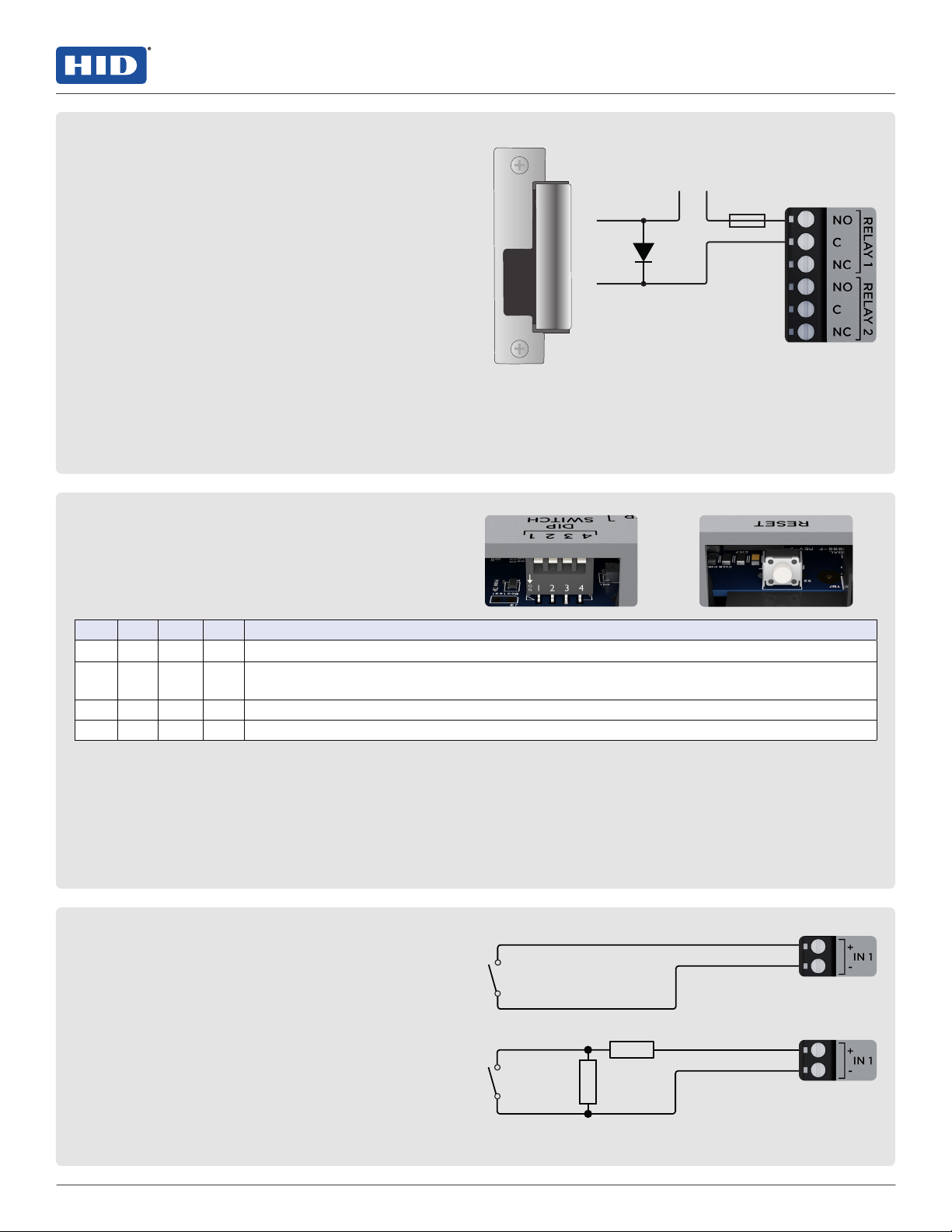
5. Relay circuit wiring
Four relays are provided for controlling door lock
mechanisms or alarm signaling.
When controlling the delivery of power to the door
strike, the NO (Normally Open) and C(Common) poles
are typically used.
When momentarily removing power to unlock the door,
as with a mag lock, the NC (Normally Closed) and C
(Common) poles are typically used.
Check with local building codes for proper egress door
installation.
CAUTION
Door lock mechanisms can generate feedback to the
relay circuit. This can cause damage and premature
failure of the relay, eecting the operation of the
X1100. Use a diode to protect the relay. Use a wire of
sucient gauge to avoid voltage loss.
Diode selection:
Diode current rating: 1x strike current.
Diode breakdown voltage: 4x strike voltage.
For 12 V DC or 24 V DC strike, diode 1N4002
(100V/1A) typical.
6. DIP switch configuration
The four DIP switches are used to configure the
operating mode of the X1100 processor. DIP switches
are read on power-up except where noted.
Press RESET switch to reboot the X1100.
1 2 3 4 DEFINITIONS
OFF OFF OFF OFF Normal operating mode.
ON X OFF OFF After initialization, enable default User Name (admin) and Password (password). The
switch is read on the fly, no need to re-boot. For additional information, See page 5.
OFF ON OFF OFF Use factory default communication parameters.
ON ON OFF OFF Bulk Erase prompt mode at power up. See page 5.
Note: All other switch settings are unassigned and are reserved for future use. X = don’t care.
Note: In the factory default modes, the downloaded configuration/database is not saved to flash memory.
Factory default communication parameters
Network: static IP address: 192.168.0.251
Subnet Mask: 255.255.0.0
Default Gateway: 192.168.0.1
DNS Server: 192.168.0.1
Primary Host port: IP server, Data Security: TLS if
Available, port 3001, communication address: 0
Alternate Host Port: Disabled
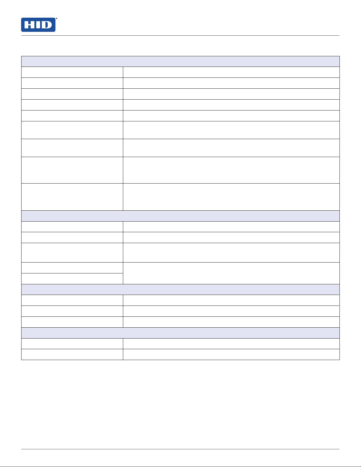
Unsupervised circuit IN 1 to IN 4
Supervised circuit IN 1 to IN 4
7. Input circuit wiring
Inputs are typically used for the following:
To monitor door position.
Request to exit.
Alarm contacts.
Input IN 1 to IN 4 circuits can be configured as
unsupervised or supervised and can use normally open
or normally closed contacts.
For a supervised circuit, add two 1KΩ, 1% resistors as
close to the sensor as possible.
Custom end of line (EOL) resistances may be configured
via the host software.
Note: The input circuit wiring configurations shown are
supported but may not be typical.
1K,1%
1K,1%

5PLT-04233, Rev. A.3
HID Aero™ X1100 Installation Guide
Powering
Trusted Identities
Bulk erase configuration memory
The bulk erase function can be used for the following:
Erase all configuration and cardholder database (sanitize board, less third party applications).
Recover from database corruption causing X1100 board to continuously reboot.
Note: If clearing the memory does not correct the initialization problem, contact technical support.
Bulk erase steps
1. Set DIP switches 1 and 2 to ON, and 3 and 4 to OFF.
2. Apply power to the X1100 board.
3. LED ONLINE is on for about 15 seconds while the X1100 boots up.
4. Change DIP switches 1 or 2 to OFF within 10 seconds, after LEDs ONLINE and HOST COMM and LEDs IO INTERNAL
and IO PORT 1 start flashing alternately at a rate of 0.5 seconds.
Note: If these switches are not changed, the X1100 board will power up using the OEM default communication
parameters.
5. LED HOST COMM will flash, indicating that the configuration memory is being erased.
Note: Full memory erase takes up to 60 seconds.
6. When complete, only LEDs ONLINE and IO PORT 1 will flash for about 3 seconds.
7. The X1100 board will complete its initialization two seconds after LEDs ONLINE & IO PORT 1 stop flashing.
CAUTION: Do not remove power during the bulk erase process.
IT security
Ensure that the X1100 is installed securely. Create user
accounts to the web configuration page using secure
passwords.
Ensure that all DIP switches are in the OFF position for the
normal operating mode.
After powering up the X1100 and connecting Ethernet,
connect to the X1100 configuration manager by opening a
browser and connecting to 192.168.0.251.
The X1100 is shipped with a default login account, which
is enabled when DIP 1 is moved from OFF to ON (See step
6. DIP switch configuration). The default login User Name
(admin) and Password (password) will be available for
five minutes once the DIP switch is toggled. It is therefore
important that at least one user account is defined, and
the DIP switches are set to OFF before the X1100 is
commissioned.
Configuring the X1100 with an IP address that is accessible
from the public Internet is not recommended.
The following options are available to improve network
security:
Disable SNMP.
Disable Zeroconf discovery.
Disable the web configuration module.
Enable data encryption over the host
communication port.
8. Input power, cabinet tamper, and UPS fault input wiring
The X1100 requires 12-24 V DC power. Connect power
with minimum of 18 AWG wire.
Connect the power ground to earth ground in only
ONE LOCATION within the system. Multiple earth
ground connections may cause ground loop problems
and is not advised.
Observe POLARITY on 12-24 V DC input.
Connect the AC FAIL and BATT FAIL inputs to the
corresponding contacts provided on the power supply.
Connect the TAMPER input to a tamper switch on the
enclosure.
TAMPER, AC FAIL, and BATT FAIL connections are
identical to inputs IN 1 to IN 4 and can be configured
as unsupervised or supervised. See step 7. Input circuit
wiring.

HID Aero™ X1100 Installation Guide
PLT-04233, Rev. A.36
Powering
Trusted Identities
LED POWER ON SELF-TEST NORMAL OPERATION
BATT FAIL On then OFF OFF = Inactive, ON = Active, Flash = Fault.*
AC FAIL On then OFF OFF = Inactive, ON = Active, Flash = Fault.*
TAMPER On then OFF OFF = Inactive, ON = Active, Flash = Fault.*
IN 1 On then OFF OFF = Inactive, ON = Active, Flash = Fault.*
IN 2 On then OFF OFF = Inactive, ON = Active, Flash = Fault.*
IN 3 On then OFF OFF = Inactive, ON = Active, Flash = Fault.*
IN 4 On then OFF OFF = Inactive, ON = Active, Flash = Fault.*
ONLINE ON for approximately 15 seconds
O-Line / On-Line and battery status.
On-Line = A long flash ON and a short flash OFF.
O-Line = A short flash ON and a long flash OFF.
Double flash if battery is low.
HOST COMM ON for approximately 1 second Host communication activity (Ethernet).
IO INTERNAL ON for approximately 1 second Internal IO module communication activity.
IO MODULE PORT 1 ON for approximately 1 second External IO module activity (Port 1).
IO MODULE PORT 2 ON for approximately 1 second External IO module activity (Port 2).
READER 1 ON for approximately 1 second
OSDP Mode = Flashes when transmitting data.
Wiegand or C&D Mode = Flashes when data is received,
either input.
READER 2 ON for approximately 1 second
OSDP Mode = Flashes when transmitting data.
Wiegand or C&D Mode = Flashes when data is received,
either input.
RELAY 1 OFF ON = Energized.
RELAY 2 OFF ON = Energized.
RELAY 3 OFF ON = Energized.
RELAY 4 OFF ON = Energized.
ETHERNET OFF
ETHERNET LED on Cover: Flashing = Ethernet activity
ETHERNET JACK:
Green/Left ON = good link
Yellow/Right is ON = 100 Mb/s and OFF = 10 Mb/s
*If this input is defined, every three seconds the LED is pulsed to its opposite state for 0.1 seconds, otherwise,
the LED is OFF.
Status LEDs
7PLT-04233, Rev. A.3
HID Aero™ X1100 Installation Guide
Powering
Trusted Identities
Specifications
AERO X1100
Input Voltage 12 to 24 V DC ±10%
Maximum Input Current 1.9 A (550 mA excluding readers and USB)
Micro USB Port 5 V DC, 500 mA maximum (reserved for future use)
Memory and Clock Backup Battery 3 Volt Lithium, type CR2032
microSD Card Format: microSD or microSDHC; 2GB to 8GB (reserved for future use)
Host Communication Ethernet: 10Base T/100Base-TX
Micro-USB port (2.0)
IO Modules Two independent ports: 2-wire RS-485, 2,400 to 115,200 bps, asynchronous,
half-duplex, 1 start bit, 8 data bits, and 1 stop bit
Inputs
Seven unsupervised/supervised, standard EOL: 1k/1kΩ, 1%, ¼ watt
(Includes TAMPER, AC FAIL, and BATT FAIL inputs)
UL evaluation for access control use only
Output
Four relays, Form-C with dry contacts:
Normally open contact (NO): 5 A @ 30 V DC resistive
Normally closed contact (NC): 3 A @ 30 V DC resistive
READER INTERFACE
Power 12 V DC ±10%, 500 mA maximum each reader
Data Inputs TTL compatible or 2-wire RS-485
OSDP (RS-485) Mode 9,600 to 230,400 bps, asynchronous, half-duplex, 1 start bit, 8 data bits,
and 1 stop bit. Maximum cable length: 2000 ft. (609.6 m)
LED Output
Open collector, 12 V DC open circuit maximum, 40 mA sink maximum
Beeper Output
ENVIRONMENTAL
Operating Temperature 32 to 158°F (0 to +70°C)
Storage Temperature -67 to 185°F (-55 to +85°C)
Humidity 5 to 85% RHNC
MECHANICAL
Dimension 6.46" × 5.51" × 1.02" (164 mm × 140 mm × 26 mm)
Weight 352 g
These specifications are subject to change without notice.

hidglobal.com An ASSA ABLOY Group brand
HID Aero™ X1100 Installation Guide
Powering
Trusted Identities
Powering
Trusted Identities
PLT-04233, Rev. A.3
Brazil
Condomínio Business Center
Av. Ermano Marchetti, 1435
Galpão A2 - CEP 05038-001
Lapa - São Paulo / SP
Brazil
Phone: +55 11 5514-7100
Asia Pacific
19/F 625 King's Road
North Point, Island East
Hong Kong
Phone: 852-3160-9833
Americas & Corporate
611 Center Ridge Drive
Austin, TX 78758
USA
Phone: 866-607-7339
Europe, Middle East & Africa
3 Cae Gwyrdd
Green Meadow Springs
Cardi CF15 7AB
United Kingdom
Phone: +44 (0) 2920 528 500
15
E4662
Complies with
IMDA Standards
DB106440
Singapore
Regulatory
UL Recognized Component (UL294)
All National and local Electrical codes apply.
This equipment is intended to be powered from a limited power source output, of a UL294 Certified Power Supply.
Install in accordance with NFPA70 (NEC) Local Codes, and authorities having jurisdiction. Follow all National and
Local Codes.
Changes or modifications not expressly approved by the party responsible for compliance could void the user’s authority
to operate the equipment.
UL 294 Performance Levels
MODEL # ACCESS CONTROL
LINE SECURITY LEVEL
DESTRUCTIVE
ATTACK LEVEL
ENDURANCE
LEVEL
STAND-BY
POWER LEVEL CONDITIONS
X1100 Level I Level I Level IV Level I
US-FCC:
Class A Digital Devices FCC Compliance Statement:
This equipment has been tested and found to comply with the limits for a Class A digital device, pursuant to part 15
of the FCC Rules. These limits are designed to provide reasonable protection against harmful interference when the
equipment is operated in a commercial environment. This equipment generates, uses, and can radiate radio frequency
energy and, if not installed and used in accordance with the instruction manual, may cause harmful interference to radio
communications. Operation of this equipment in a residential area is likely to cause harmful interference in which case
the user will be required to correct the interference at their own expense.
Taiwan-BSMI Class A Notice
警告使用者:
這是甲類的資訊産品,在居住的環境中使用
時,可能會造成射頻干擾,在這種情況下,
伊用者會被要求採取某些適嘗的酎策。
Your HID product is marked to indicate its compliance class:
Federal Communications Commission (FCC) – USA
Industry Canada Equipment Standard for Digital Equipment (ICES-003) – Canada
CE Mark – Europe
RCM Mark – New Zealand and Australia
Voluntary Control Council for Interference (VCCI) – Japan
Bureau of Standards Metrology and Inspection (BSMI) – Taiwan
Infocomm Development Authority (IDA) – Singapore
Korea Communications Commission (KCC) – Korea
UL Recognized Component (UL294)
Japan
この装置は、クラスA機器です。この装置を住宅環境で使用す
ると電波妨害を引き起こすことがあります。この場合には使用者が適切な
対策を講ずるよう要求されることがあります。VCCI -A
Table of contents
Other HID Controllers manuals

HID
HID Mercury LP1501 User manual

HID
HID Signo 25B User manual

HID
HID Mercury LP4502 User manual

HID
HID VertX EVO V1000 User manual

HID
HID ACW2-XN User manual

HID
HID Mercury LP1502 User manual

HID
HID VertX EVO V2000 User manual

HID
HID iCLASS SE RB25F User manual

HID
HID Vertx CS V100 User manual

HID
HID EDGE EVO EH400-K User manual


