BeingHD VPX-500 User manual
Video Wall Processor
8 DVI-I inputs and 12 DVI outputs Video Wall controller with Preview function
Version number: V1.01.01
User Manual
1
1. Introduction
This video wall processor is a high-end video processing equipment developed and manufactured
by our company for LCD large screen display and so on. It has adopted the CrossInt smart splicing
technology specially designed for splicing display and all display modules are locked by FST
technology before synchronous output, eliminating the asynchronous display between contents
of multiple modules.
2. Features
Supports 8 DVI-I inputs Compatible with DVI/HDMI/VGA/CVBS).
Up to 8 layouts/windows in total
Colorful LCD screen for the real-time information and menu setting
Supports sources real-time preview function(with 1000M LAN port)
All 60Hz image processing, achieving smooth and non-tearing images
Support output port mapping, allowing blind wire connections
Support black/blue screen while wrong sources output
Support mode and source switching effects(CUT of FADE effects)
2.Hardware Introduction
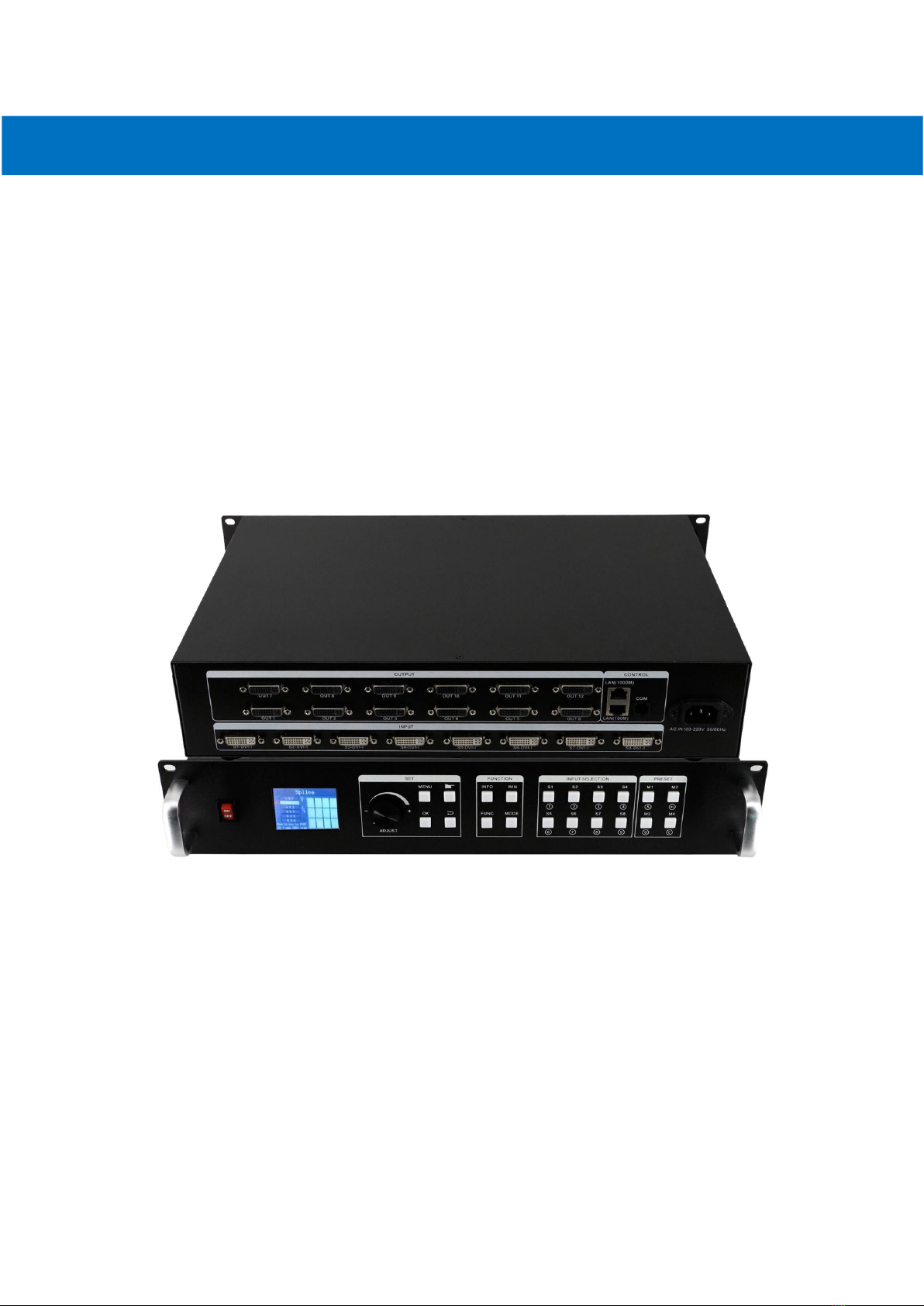
2.1 Front Panel
1POWER: Power switch ON/OFF
2Colorful LCD screen: for fast setting, information look up
3SET: including ADJUST knob, OK, MENU, BACK and CONFIRM
4FUNCTION: Function key area which includes INFO, WIN, FUNC, MODE
5INPUT SELECTION: 8 signal sources fast switching buttons
6PRESET: User-Mode recall buttons
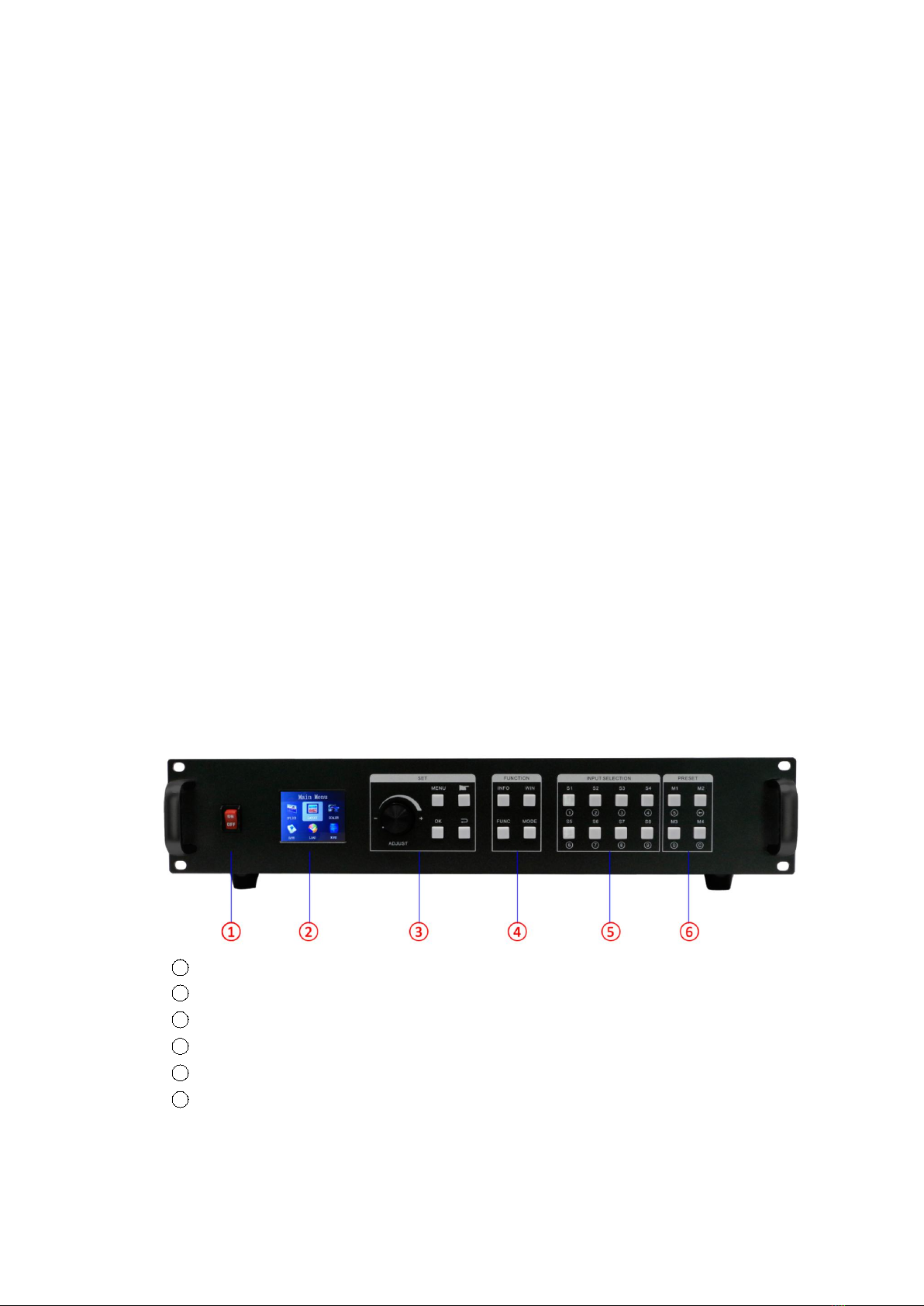
2.2 Back panel
2
1INPUT: 8 DVI-I input ports (Compatible with DVI/HDMI/VGA/CVBS)
22OUTPUT: 12*DVI output ports
3CTRL: Control port which contains LAN (100M), LAN (1000M), COM (serial port)
4POWER: Power supply port, AC 110-220V 50/60Hz
3. Specification
Video Inputs
Type
Qty
Description
DVI-U
8
Support up to 1920×1200@60Hz, downward compatibility.
Support DVI/HDMI/VGA/CVBS with different connectors
Compatible with HDMI1.3 and lower version, EDID version 1.3
Video Outputs
Type
Qty
Description
DVI-D (24+1)
12
Resolutions: 1024×768@60Hz till 1920×1080@60Hz
Support 60Hz/50Hz/30Hz output frame rates
Function Description
Outputs
12 outputs support splicing mode of arbitrary form, such as: 3×4, 2×6 etc.
8 layouts/windows
Up to 8 windows or layouts in total
Each layout can be freely zoomed and adjusted. Images can overlap each other.
1000M Preview
The signal image can be gained on computer at real time by control software
which includes both input signal and output signal
Switching Effect
When switching signals or user-modes, users can set up different effects and time
Others
PC Control
RS232/RJ45 Ethernet
Dimension
440x290x90mm
Weight
5.4kg
Input Power
100-220V 60/60Hz

3
Work Environment
Temp: 0-40℃; Humid: 0-95%
Warranty
2 years
4. Device Debugging
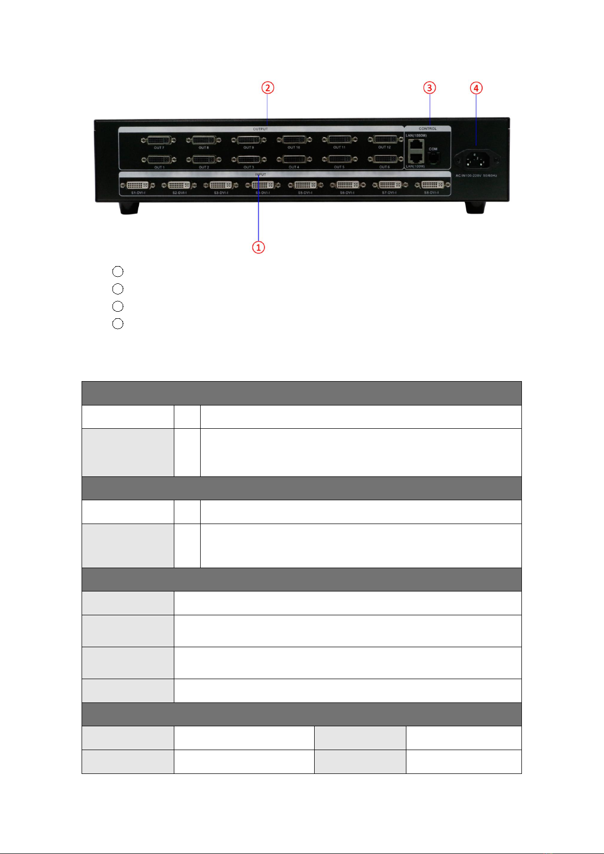
4.1 Device Connection
Device connection could be divided into three parts: power connection, signal connection
and control connection (used for software debugging).
Power connection: device power supply. Connection method: connect power cord to power
plug.
Signal connection: the method transferring signal from signal source to LED large screen,
method: signal source (e.g.: computer)→Mosaic Processor →LCD.
Control connection: connect control computer with device control port and debug device
connection method. There are three connection methods
(1) Connect 100MB network control port with splicer LAN(100M) port, which can set device
software
(2) Connect computer gigabit network port with splicer LAN(1000M) port, which can not
only set device but also echo signal source image.
(3) Connect one crystal head of serial port line which is randomly donated by device with
splicer COM port, and plug DB9 into computer serial port. Any kind of method among the
three can realize device software control.
Connection diagram:
4
4.2 Debugging Steps
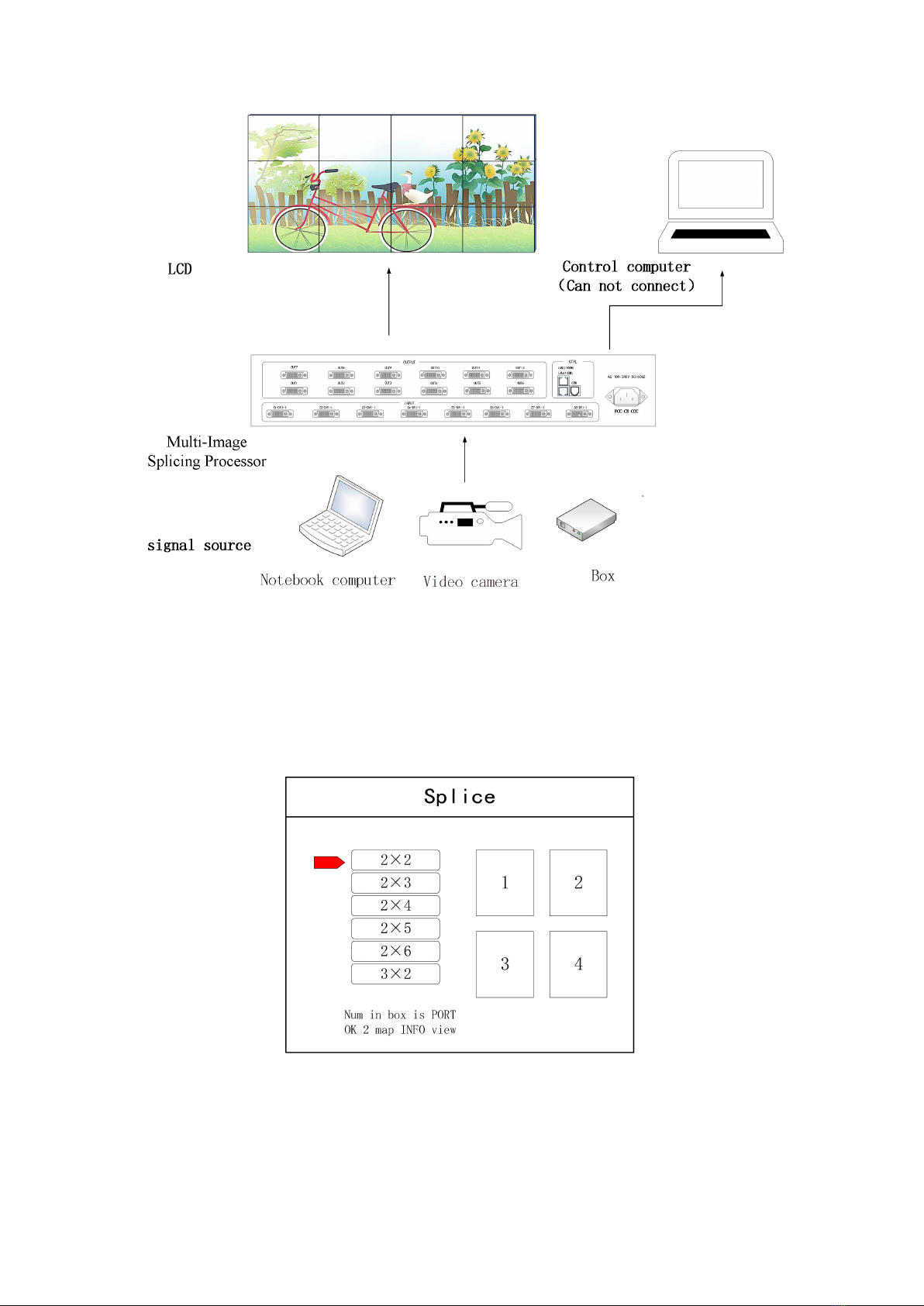
Step 1: Press “MENU”to enter into main menu interface and click “Splicing Mode”to select
splicing mode: 2×2、2×3、2×4、2×5、2×6、3×2、3×3、3×4、4×2、4×3、5×2、
M×N.
Note: Select M * N to customize the stitching method
Step 2: To get back to main menu interface to select “Image layout”and enter into image
number selecting interface to select image number required to be set.
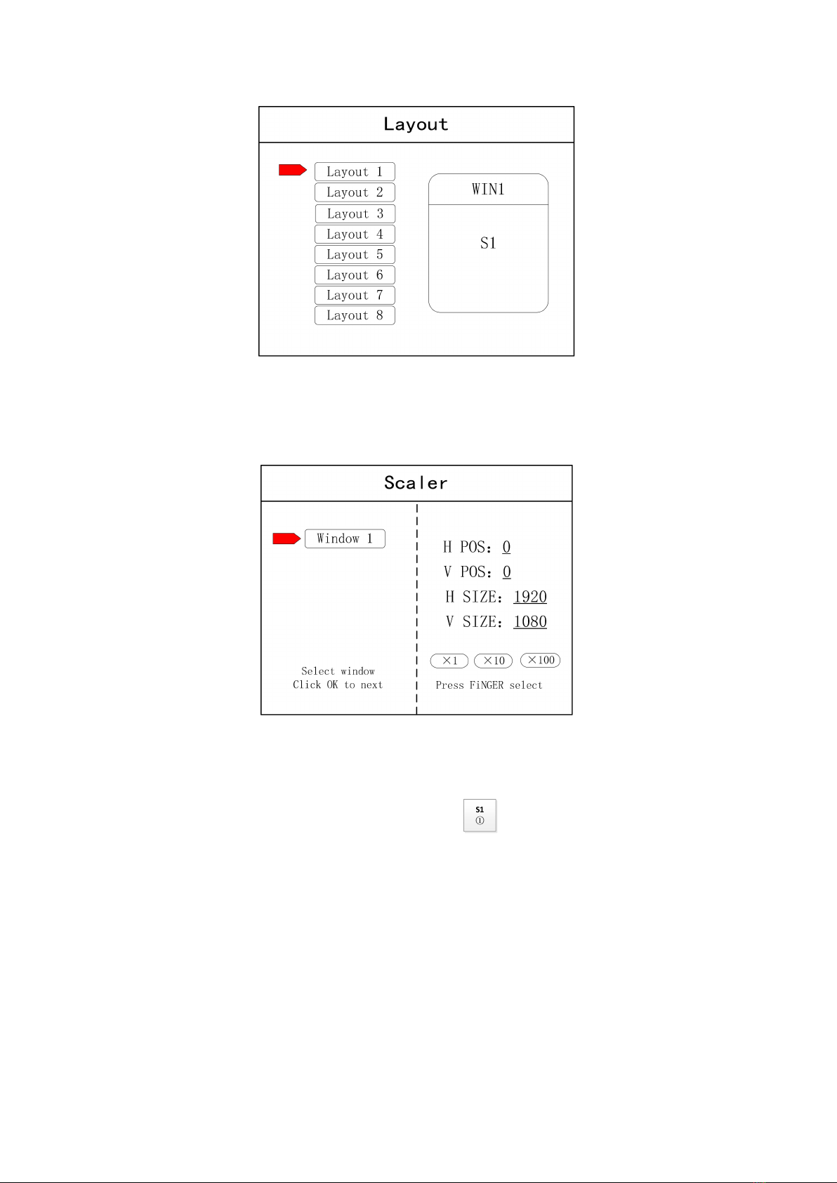
5
Note: This step can be skipped for signal image. For multi-image, it’s OK if image number and item
requirement are in consistent. Following operations can be taken to set when layout are not in consistent.
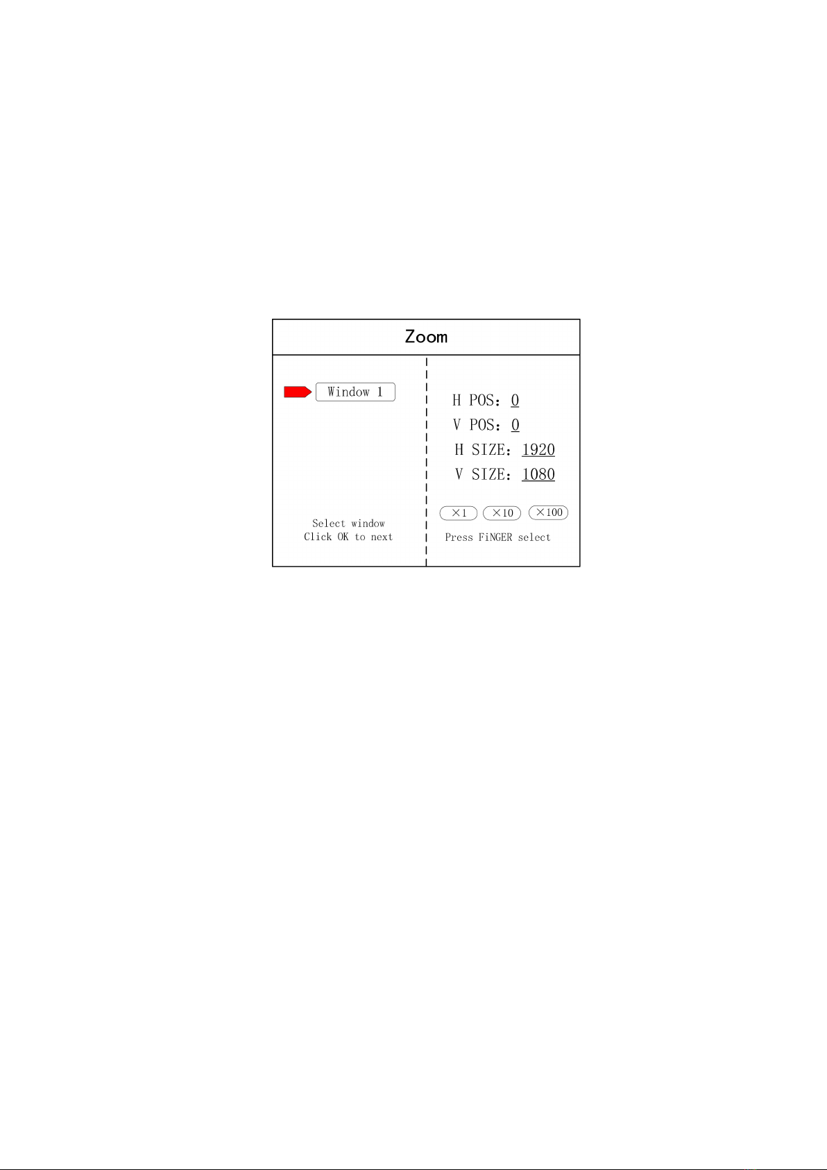
Step 3: Press “OK”and return to main menu interface; select “Image parameter”and enter into
its setting interface to set size and position of each image.
Note: there are two ways for number input:
(1) Adjust by rotate knob. Step length can be adjusted by “×1” “×10”“×100”, for instance, “×100”means that
number of rotate knob increases by 100 each time.
(2) Input by number of the front panel. For example, of the key refers to figure 1.
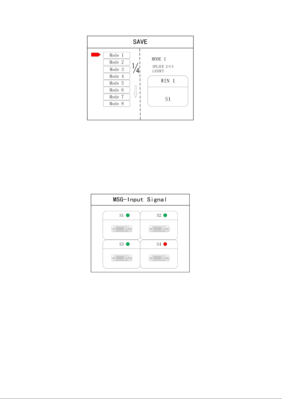
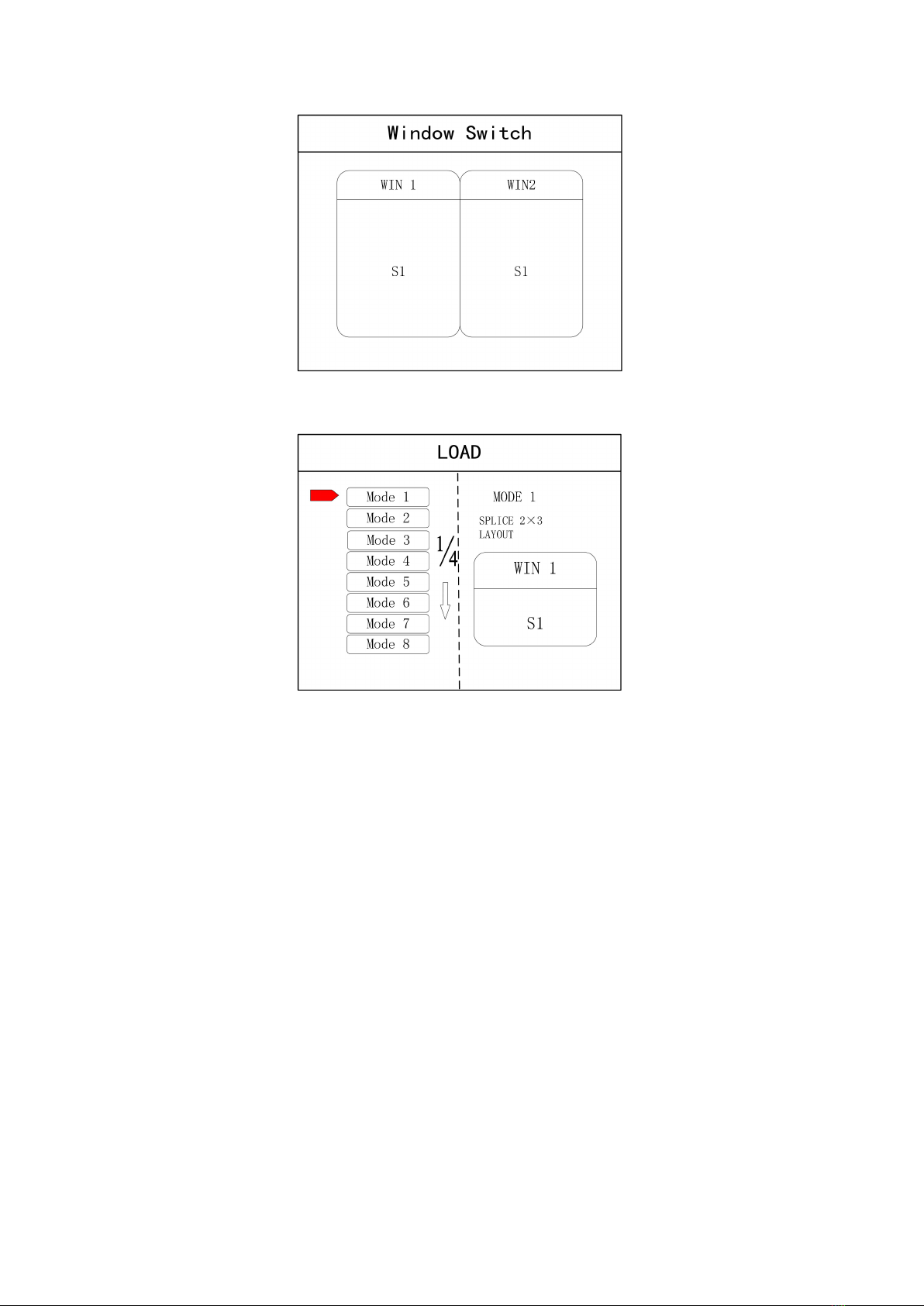
Step 4: Press “MENU”and return to main menu interface; select “Save setting”to enter into Data
storage interface; select any mode and click “OK”to save data.
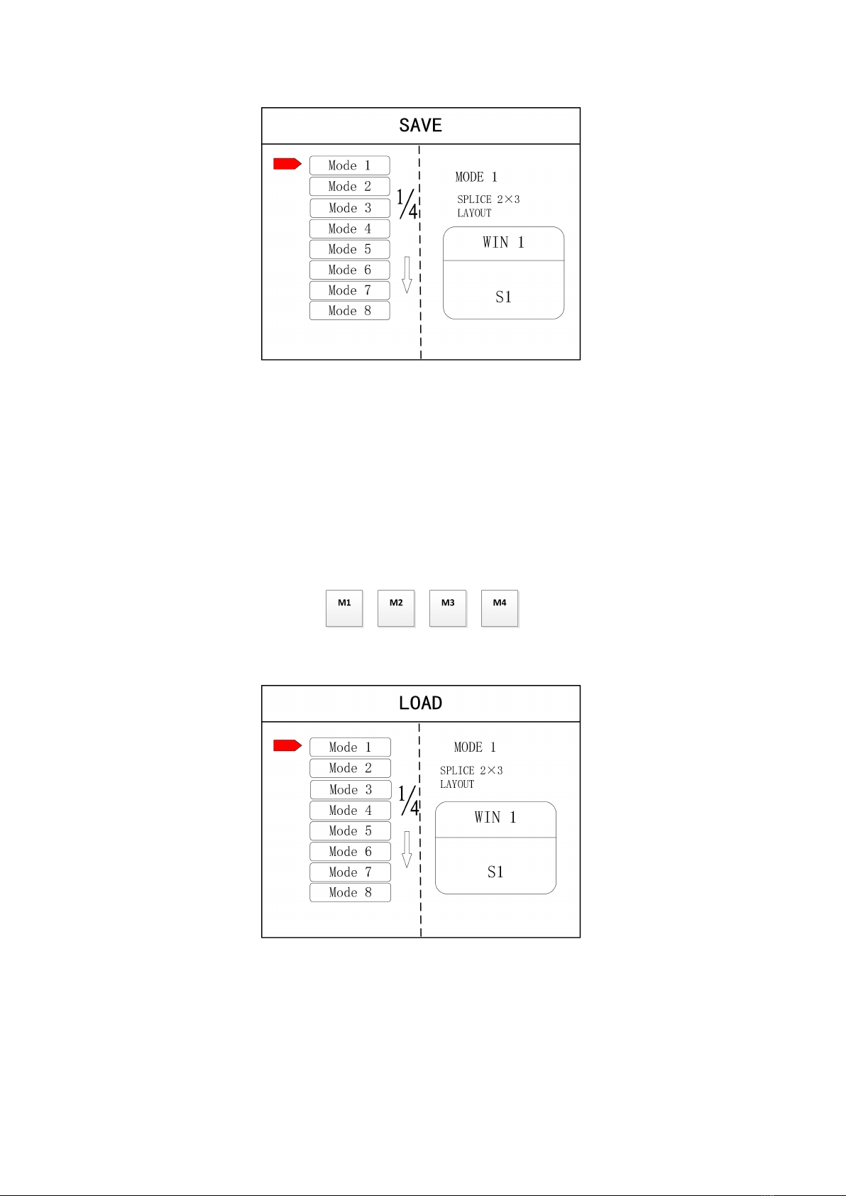
6
Note: Mode 1 is default startup data of device boot; it’s suggested that the most common mode or that
required by device boot should be saved to Mode 1.
At this point, basic device debugging is completed. If there is other requirement, repeat the
operation and save it as other mode.
After device debugging, just recall saved data according to different condition requirements in
later stage.
Data recall is divided into forms:
(1) For Shortcut key call, only select and press the “M1-M4”buttons on the front panel which
is convenient when mode scenario is few.
(2) For users to recall from the Main Menu, press “MENU”and select “User Mode”to enter
into its extraction interface. Then select needed mode and click “OK”.
4.3 Case Study
Device debugging steps are explained by following cases.
Case: There are 12 LCD screens arranged in 3 rows and 4 columns, as shown in the following figure:
Requirement: all LCD screens are spliced together as a whole one :
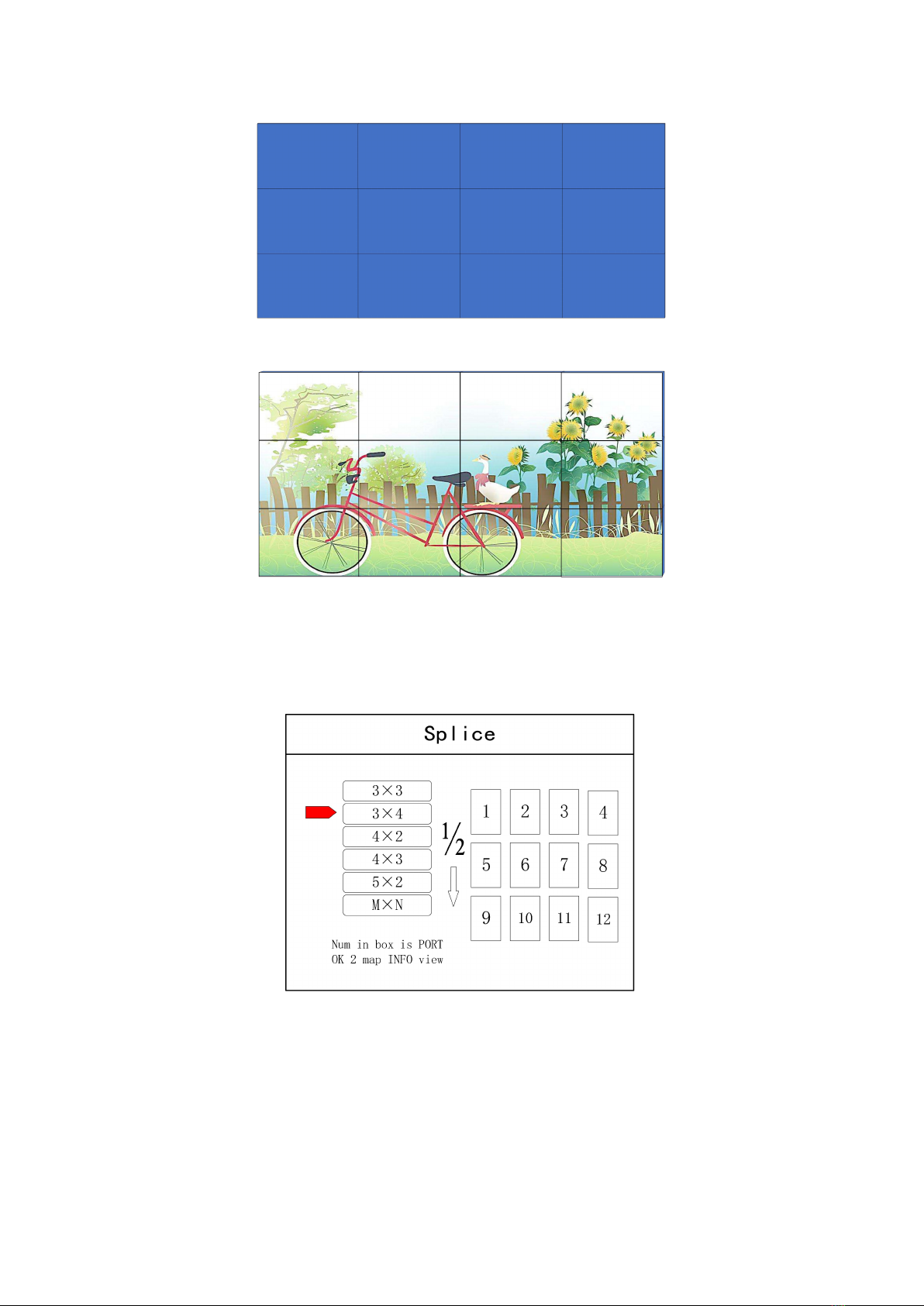
7
Arrangement of LCD screen
Display chart
Debugging Steps:
Step 1: Press “MENU”and enter into main menu interface to select “Cross Mosaic”of the first
item “Device mode”.
Step 2: Press “OK”to return to main menu interface; The large screen splicing is finished,
select signal source needed to display on screen and click corresponding key(s1-s8).
Step 3: After normal display of large screen, save all setting data. Press“Save setting”to enter
into “Save setting”interface to select “Mode 1”and click “OK”. Things will be fine when it
suggests saving successfully.
8
Note: Mode 1 is default startup data of device boot; it’s suggested that the most common mode should be
saved to Mode 1 and the device can save 32 kinds of modes at most.
4.4 Function key:
Brief explanation of function key:
INFO: Information query key. Click this key and enter into its interface showing whether all
signal sources are inputting normally. Its interface is shown as below. Red light means signal is
lost while green one shows signal is normal.
WIN: Image key. Click this key to enter into its interface and signal source selection can be
made in following interface.
9
MODE: Mode recall key…Press this button to enter the user mode interface, and users can
recall the saved modes
FUNC: Function key. Press this key to enter into its interface which includes: brightness
adjustment, special effect switch, VGA adjustment, image matting setting, edge feather,
transparency setting, intelligent warm backup, preview monitor, IP setting, serial port, freeze
frame, local and global, color space, input brightness and switch time. The following are
explanations of those common functions.
1. Brightness adjustment
The device supports 1-255 stairs brightness adjustment. Brightness of all screen body can
be adjusted synchronously to meet customers’different brightness adjustment
requirements for different conditions.
2. Output condition
Use this button to set black screen or blue screen, and then you can switch the output
state.
3. Special effect switch
The device supports directly switching the fade-in and fade-out effect, and ensures that
the switching process is without flower screen, flash screen or black screen.
4. Special effect time
Set image switch times or switch time among different modes with the range of 0.2s-3s.
5. VGA adjustment
10
Since VGA signal belongs to analogue one, it tends to causes deviations among common
functions. The product has two kinds of VGA corrections which are automatic correction
and manual correction.
6. IP setting
Set device IP address for software debugging.
7. Clipped view
Specifies that the full screen of the signal source is placed on the screen in a particular
area. You can set the specified location and size of the signal source. The value "0"
represents no clipped view.
8. Local and global
Switch local display or global display of certain image on the condition that data of local
display is already set.
9. Freeze frame
Set stillness or movement of certain image which is often used for field change or
background switch.
10. Freeze full screen view
Set all images immobile or mobile.
11. Serial port setting
Set device serial port like baud rate and etc.
12. Output mapping
Set splicing mode and output port mapping.
4.5 Advanced Menu
Language setting
Set device language: English or Chinese
Output resolution
Support single output resolution, user-defined resolution is available and support 30HZ,
50HZ and 60HZ frame rate. Device default output resolution is 1920×1080@60HZ.
Factory setting

11
All data are cleared and the device returns to default state.
Common functions
Click “FUNC”to get quick access to common setting function.
Keyboard lock
Lock front panel key to avoid misoperation of irrelevant personnel.
Technical Support
Inquire device version number and its IP address.
5. Software Control
Step 1: Please click and download the control software at Google drive by clicking:
https://drive.google.com/open?id=1B9ReI8ZJrcfrtnLLAkti3LUnAaEmiDN5
Step 2: Extract the rar. File and install the control software on the control PC
Step 3: After install, double click to run the software.
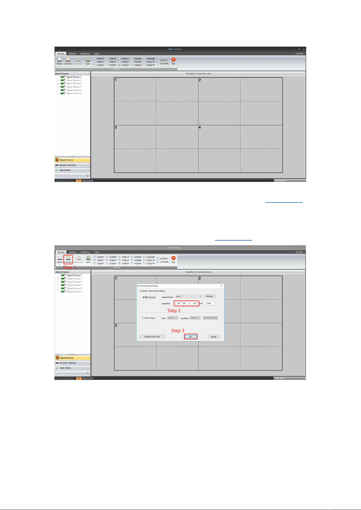
The default User name is: administrator, no password, click “ok” to login and it will show below
interface:
12
Before getting started, please make sure the control PC and controller is connected either by LAN
or RS232 cable: If using the LAN control, the default IP address of the controller is 192.168.0.100,
please also make sure the control PC and controller is at the same gateway. For using the RS232,
please check and confirm which COM port is available on the PC.
Below will be showing on using the IP control.
3 steps to get connected: Click “Connect”, Type the IP address 192.168.0.100, then click “OK”
After well connected, it will pop-up a window for synchronination with the control software, click
to “OK” to sync.

13
After click “OK” to sync, it will jump to “Switching” interface:
“Switching” interface, there are several sections:
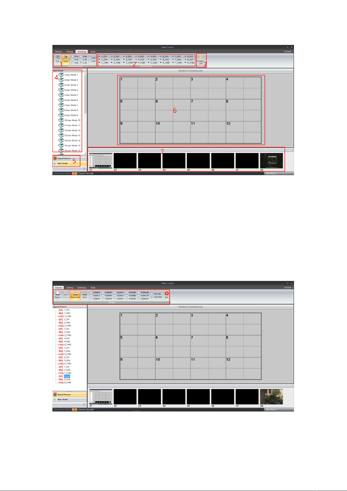
14
1: For the switching effects and time setting: Fade or Cut
2: 8 Signals type DVI/VGa/CVBS
3: Window position lock button
4: Display the details of the User Modes or the Signal sources
5: Collapse for the User Mode or the Signal Source
6: Video Wall Operation area
7: For the local sources preview(only with 1000M LAN port can support)
“Device” Interface:
After click “Device”, it will be showing as below: For this model, we only use the “Connect/
disconnect” and “Exit” two buttons, the rest are for other equipment.
“Setting” Interface:
15
Users can set the video wall configuration accordingly. Open new window, save or recall users
mode, and default back to factory mode and so on function here.
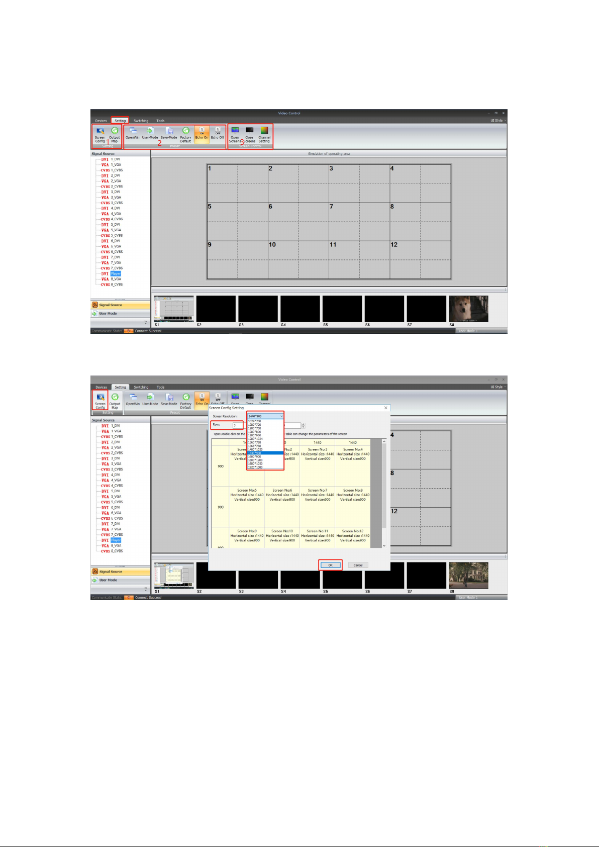
Screen config and Output Map:
Screen config(for the Video wall number and resolution settings):
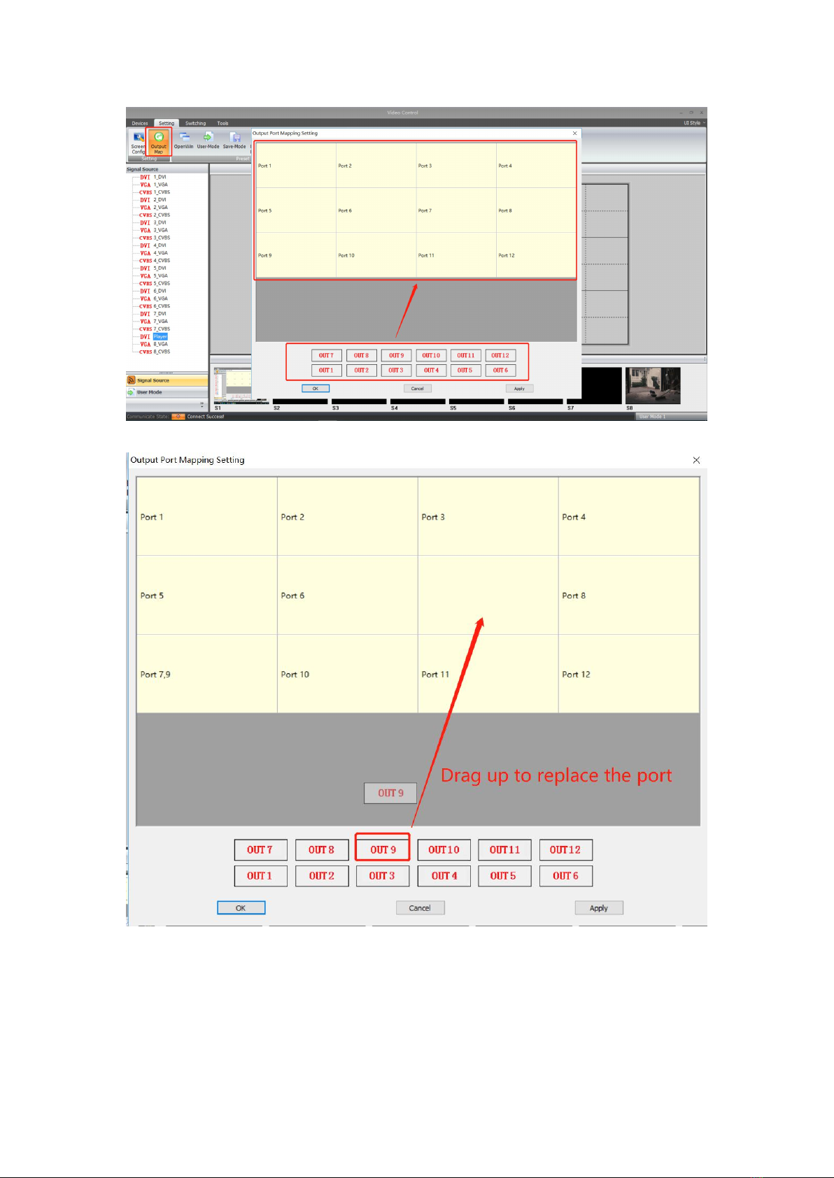
Output Map(for adjusting the output ports to match with the displays):
16
Drag the OUT1...OUT12 up to the Port1...Port12 to replace and adjust
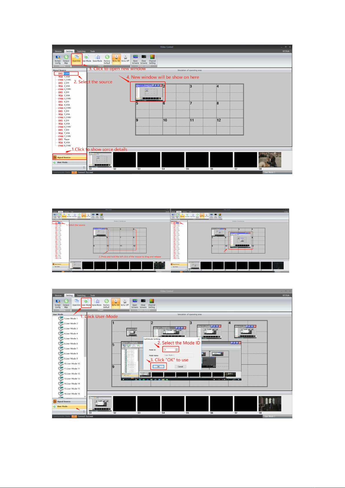
2: Open Win, User-mode, Save-Mode, Factory Default, Echo on/off
Open Win: to open a new window on the Video Wall
17
For open a window, it also can be done by pressing and holding left click of the mouse to drag
and release on the video wall operation area, and users can adjust the window size by moving to
the edge of the window:
User-Mode: For recalling the saved user mode(presets), total can save 32 presets
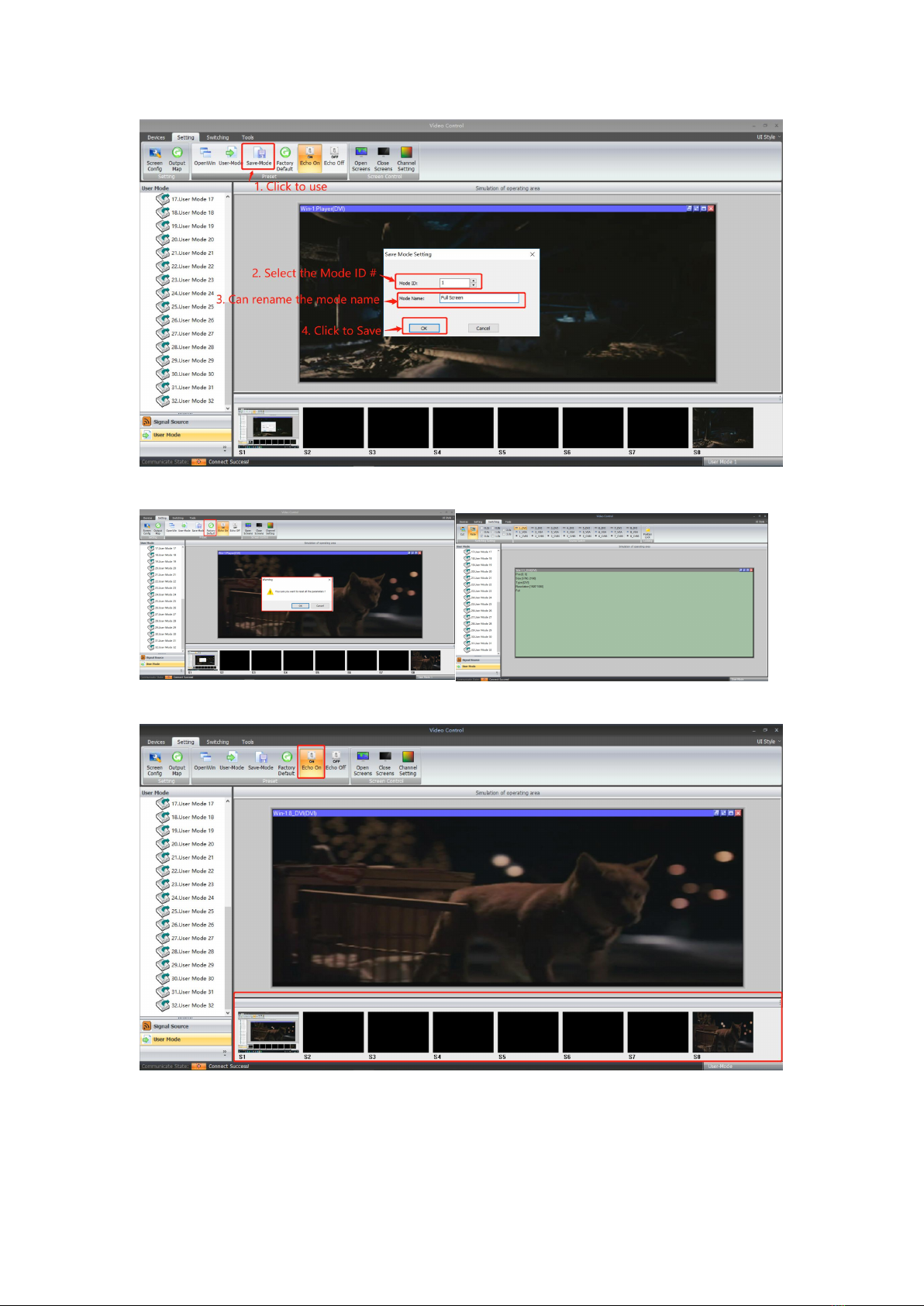
Save-Mode: For save the current settings as a user-mode/preset
18
Factory default: Click this one will reset all the parameters as factory default mode
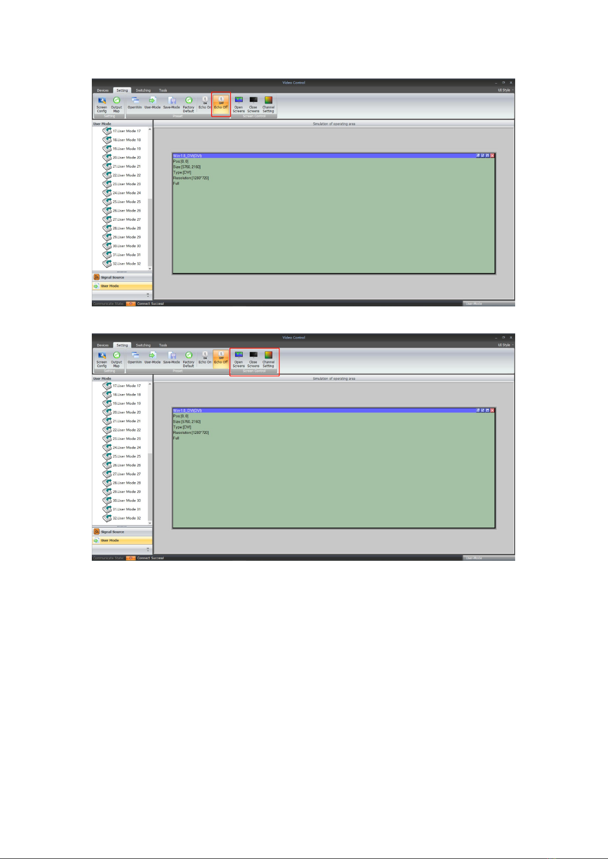
Echo On: Turn on the local preview function on the control PC(only support with 1000M Port)
Echo Off: Turn off the local preview function on the control PC(only support with 1000M Port)
19
Screen Control: those functions are not available for this mode
“Tools” interface
With interface, users can add more operation users here with different rights, language setting
and also change to baud rate and IP address:
Table of contents
Popular Media Converter manuals by other brands


H&B
H&B TX-100 Installation and instruction manual

Bolin Technology
Bolin Technology D Series user manual

IFM Electronic
IFM Electronic Efector 400 RN30 Series Device manual

GRASS VALLEY
GRASS VALLEY KUDOSPRO ULC2000 user manual

Linear Technology
Linear Technology DC1523A Demo Manual

Lika
Lika ROTAPULS I28 Series quick start guide

Weidmuller
Weidmuller IE-MC-VL Series Hardware installation guide

Optical Systems Design
Optical Systems Design OSD2139 Series Operator's manual

Tema Telecomunicazioni
Tema Telecomunicazioni AD615/S product manual

KTI Networks
KTI Networks KGC-352 Series installation guide

Gira
Gira 0588 Series operating instructions

Lika
Lika SFA-5000-FD user guide