BEKA Stream H Product guide

Page 1 © BEKA 2019 All rights reserved!
...a product of
BAL2522_2523_Barrel_pump_Stream_H_0619EN
Barrel pump
BEKA Stream H
Article no. 2522 ….; 2523 ….
Issue 06-2019
Original operating
and
assembly manual

Page 2 © BEKA 2019 All rights reserved!
...a product of
BAL2522_2523_Barrel_pump_Stream_H_0619EN
Table of contents
1.Technical data ................................................................................................................................................................................4
1.1General......................................................................................................................................................................................4
1.2Pump individually.......................................................................................................................................................................4
1.3Pump – barrel version................................................................................................................................................................ 4
1.4Pump – container version..........................................................................................................................................................4
1.5Solenoid valve – single-line version...........................................................................................................................................4
1.6Level monitoring ........................................................................................................................................................................4
2.Applicable documents.....................................................................................................................................................................5
3.Code ...............................................................................................................................................................................................5
4.Versions..........................................................................................................................................................................................7
5.General safety instructions .............................................................................................................................................................9
5.1Safety instructions .....................................................................................................................................................................9
5.2Qualification and training of staff ...............................................................................................................................................9
5.3Hazards in case of non-observance of the safety instructions ................................................................................................10
5.4Obligations of the operator / user ............................................................................................................................................10
5.5Safety instructions for maintenance, inspection and assembly ...............................................................................................10
5.6Unauthorized modification and production of spare parts .......................................................................................................10
5.7Inadmissible modes of operation.............................................................................................................................................11
5.8Electrostatic discharge............................................................................................................................................................. 11
5.9General hazard warning – residual risk ...................................................................................................................................11
6.Intended use.................................................................................................................................................................................12
7.Scope of warranty.........................................................................................................................................................................12
8.Transport and storage ..................................................................................................................................................................13
8.1Pump .......................................................................................................................................................................................13
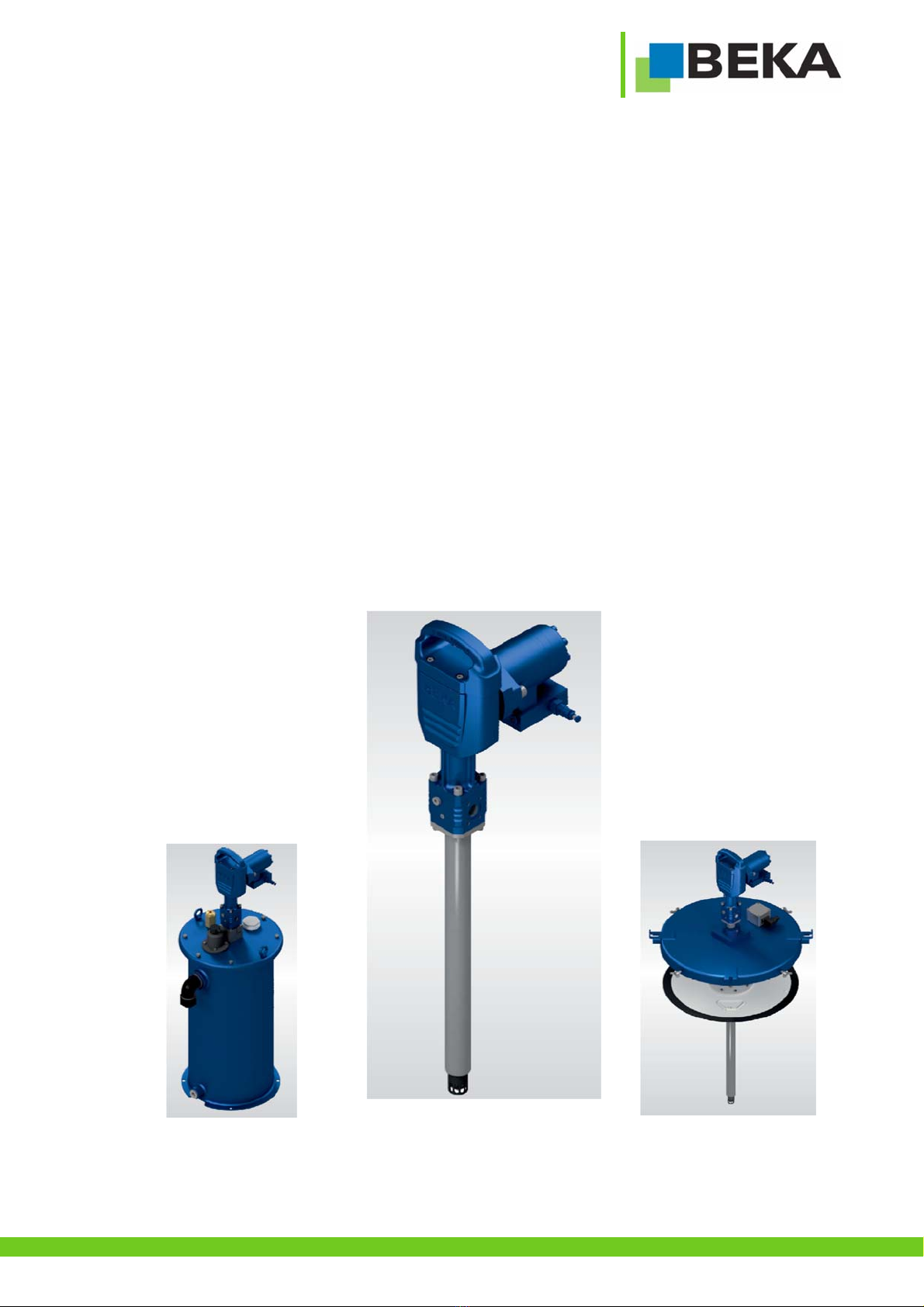
8.2Beka Stream H barrel version..................................................................................................................................................13
8.3Beka Stream H container version............................................................................................................................................13
9.Assembly instructions...................................................................................................................................................................14
9.1Prefilling of return connection (lubricant) ................................................................................................................................. 14
9.2Assembly of Beka Stream H barrel version.............................................................................................................................16
9.3Assembly of Beka Stream H container version .......................................................................................................................16
9.4Hydraulic connection of the motor ...........................................................................................................................................17
9.5Power connection ....................................................................................................................................................................18
10.Start up .........................................................................................................................................................................................19
10.1Lubricants ................................................................................................................................................................................19
10.2Ventilation of the lubrication system ........................................................................................................................................19
10.3Adjustment of the level monitoring (barrel version) .................................................................................................................19
10.4Setting the level monitoring (container version).......................................................................................................................19
10.5Initial filling of container with lubricant .....................................................................................................................................20
10.6Delivery volume .......................................................................................................................................................................21
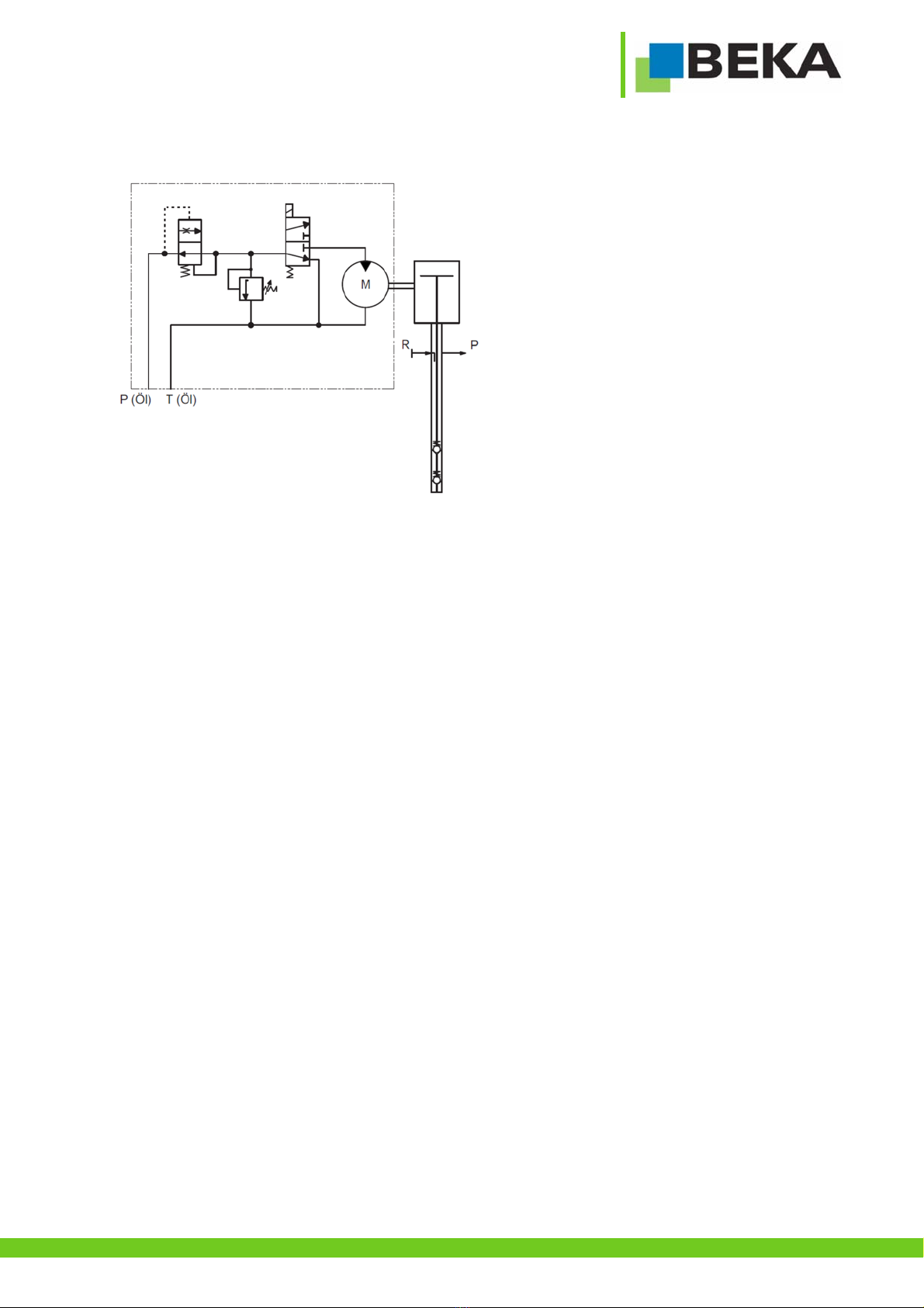
11.Functional description...................................................................................................................................................................22
11.1General....................................................................................................................................................................................22
11.2Pump .......................................................................................................................................................................................22
11.2.1Hydro motor ....................................................................................................................................................................22
11.3Add-on parts ............................................................................................................................................................................23
11.3.1Level monitoring..............................................................................................................................................................23
11.3.2Ventilation valve.............................................................................................................................................................. 23
11.3.3Grease level dipstick.......................................................................................................................................................23
11.3.4Single-line block (optional)..............................................................................................................................................23
11.3.5Pressure limiting valve (optional) ....................................................................................................................................23
12.Maintenance .................................................................................................................................................................................24
12.1General maintenance ..............................................................................................................................................................24
12.2Lubricant change .....................................................................................................................................................................24
12.3Filling of the container.............................................................................................................................................................. 25
12.4Exchange of barrel................................................................................................................................................................... 26
12.5Exchange of pump...................................................................................................................................................................27
13.Repair ...........................................................................................................................................................................................28
13.1Exchange of pump element ............................................................................................................................................28

Page 3 © BEKA 2019 All rights reserved!
...a product of
BAL2522_2523_Barrel_pump_Stream_H_0619EN
13.2Exchange of motor.......................................................................................................................................................... 32
13.3Exchange of sealing bush...............................................................................................................................................33
14.Shutdown......................................................................................................................................................................................35
15.Disposal........................................................................................................................................................................................35
16.Troubleshooting............................................................................................................................................................................35
17.Spare part list and drawing...........................................................................................................................................................35
18.Dimensional drawing of pump without accessories......................................................................................................................36
19.Dimensional drawing of pump with accessories...........................................................................................................................37
20.Accessories ..................................................................................................................................................................................38
20.1Filling zerk.......................................................................................................................................................................38
20.2Pressure limiting valve for progressive and dual-line systems .......................................................................................38
20.3Pressure limiting valve / relief valve for single-line system ............................................................................................. 38
20.4Control unit Tronic-e .......................................................................................................................................................39
20.510 m connection cable incl. 1x AMP bushing .................................................................................................................39
20.610 m connection cable for BEKA Stream H incl. 1x cubic bushing (socket acc. to EN175301-803 A)........................... 39
20.7Module with pressure limiting valve for progressive systems for direct installation on BEKA Stream H ........................40
21.Details of the manufacturer...........................................................................................................................................................41

Page 4 © BEKA 2019 All rights reserved!
...a product of
BAL2522_2523_Barrel_pump_Stream_H_0619EN
1. Technical data
1.1 General
Pump
Delivery rate: ......................................................................................................................................................................... 120 cm³/min
Lubricant:...................................................................... greases up to NLGI class 2 without solid contents (other lubricants on request)
Operating pressure basis system:...........................................max. 5076 psi / 350 bar (pressure limiting valve not in scope of delivery)
Operating pressure single-line system:.................................max. 5076 psi / 350 bar (pressure limiting valve set to 3480 psi / 240 bar)
Operating temperature: .....................................................................-22°F up to +149°F / -30°C up to +65°C (depending on lubricant)
Number of outlets:...................................................................................................................................................................................1
Outlet type:....................................................................................................................................................................................... G 1/2
Return connection (integrated in pump pipe): .................................................................................................................................. G 1/2
Sound pressure level:................................................................................................................................................................<70 dB(A)
Motor
Drive type: ...................................................................................................................................................................................hydraulic
Hydraulic oil inlet: ............................................................................................................................................................................. G 3/8
Hydraulic oil outlet: ........................................................................................................................................................................... G 3/8
Drive pressure (P): ..................................................................................................................................... 290 – 3625 psi / 20 – 250 bar
Return pressure (T): .................................................................................................................................................... max. 43 psi / 3 bar
Volume flow* of the drive medium:....................................................................................................... 0,53 – 3,2 gal/min / 2 – 12 l/min**
Purity class of the drive medium: ........................................................................................................................... ISO 4406: ≤21/19/16
1.2 Pump individually
Weight: ................................................................................................................................................................................ max. 21.3 kg
1.3 Pump – barrel version
Barrel capacity:..................................................................................................................................................... 213 l (180 kg / 400 lbs)
1.4 Pump – container version
Container capacity:....................................................................................................................41 l (60 lbs) / 54 l (90 lbs) / 68 l (120 lbs)
1.5 Solenoid valve – single-line version
Operating voltage:....................................................................................................................................................................... 24 V DC
Nominal power: .................................................................................................................................................................................26 W
Degree of protection:.........................................................................................................................................................................IP 65
1.6 Level monitoring
Operating voltage:......................................................................................................................................................... 10 up to 30 V DC
Electric version: ..................................................................................................................................................................... DC PNP NO
Connection plug: .............................................................................................................................................................. M12x1; 4-poles
Functional principle: ...................................................................................................................................................................ultrasonic
Degree of protection:.........................................................................................................................................................................IP 67
*Delivery volume depending on volume flow (see also figure 23 – page 21).
** The volume flow of the drive medium is internally limited to max. 3,2 gal/min / 12 l/min.
Please see the attached data sheets and manuals of the corresponding manufacturers for missing details and further
technical data.
The barrel pump is subsequently called a device.

Page 5 © BEKA 2019 All rights reserved!
...a product of
BAL2522_2523_Barrel_pump_Stream_H_0619EN
2. Applicable documents
Technical documentation of individual parts enclosed:
Level monitoring
Please observe these documents for all work with and at the device!
3. Code
Caution!

Page 6 © BEKA 2019 All rights reserved!
...a product of
BAL2522_2523_Barrel_pump_Stream_H_0619EN

Page 7 © BEKA 2019 All rights reserved!
...a product of
BAL2522_2523_Barrel_pump_Stream_H_0619EN
4. Versions
Pump
Pump - container version
Pump - barrel version
Symbol Symbol (basis system) Symbol (single-line system)
Fi
g
ure
2Fi
g
ure 1 Fi
g
ure 3
Fi
g
ure 5Fi
g
ure 4 Fi
g
ure
6

Page 8 © BEKA 2019 All rights reserved!
...a product of
BAL2522_2523_Barrel_pump_Stream_H_0619EN
Symbol hydro motor
Fi
g
ure 7

Page 9 © BEKA 2019 All rights reserved!
...a product of
5. General safety instructions
Everybody who is in charge of the assembly, start-up, maintenance and operation of the device must read these instructions carefully
prior to assembly and start-up of the device at the machine! Furthermore, this manual must always be available at the site of operation!
Basic instructions for setup, operation and maintenance can be found below.
5.1 Safety instructions
Observe the general safety instructions within this key chapter as well as the special safety instructions in other chapters of this
operating and assembly manual.
Warning of electrical voltage.
Safety instructions, which might cause hazards to persons in case of non-observance, are marked with the general
danger symbol.
This symbol warns of hot surfaces.
Warning of suspended loads.
Warning of material damage due to electrostatic discharge! Marks potential risks which may result in material damage,
if not avoided.
This heading is used if improper or general non-observance of the operating and assembly manual,
instructions, specified workflow and the like might result in damage.
This term is used to point out particular details.
Instructions and notes directly attached to the device have to be strictly observed and kept in readable condition!
5.2 Qualification and training of staff
The staff in charge of operation, maintenance, inspection and assembly have to be qualified accordingly. Competence,
responsibilities and supervision of staff must be clearly defined by the operator. In case the staff does not have the
necessary knowledge it has to be instructed and trained accordingly. The operator is obliged to ensure that the staff
fully understands the contents of this user information.
Notice!
Caution!

Page 10 © BEKA 2019 All rights reserved!
...a product of
5.3 Hazards in case of non-observance of the safety instructions
Results of non-observance of the safety instructions can be hazards to persons, for the environment and the
device. Non-observance of the safety instructions may result in the loss of any liability claims. The non-observance
could more specifically result in the following hazards (for example):
Failure of important device functions.
Failure of prescribed methods regarding maintenance and repair.
Danger to persons by electrical, mechanical and chemical effects.
Danger to the environment by leakage of hazardous substances.
5.4 Obligations of the operator / user
If movable, rotating, hot or cold parts of the device bear risks, the customer must protect these parts against
contact. This protection must not be removed.
Any leakages of hazardous substances must be drained in a way that no risks for persons or the environment
arise. Please also refer to the data or safety data sheets of the respective manufacturers.
Observe all legal provisions.
Hazards due to electricity are to be excluded.
Examination of pipes and hoses regarding safe provision, use, proper assembly and function has to be carried out
according to regionally applicable directives. Inspection intervals may not be exceeded.
Defective pipes or hoses must be replaced immediately and professionally.
Hydraulic hoses and polyamide pipes are subject to natural aging and have to be exchanged in regular intervals
according to the manufacturer’s specifications.
A safety data sheet of the currently used lubricant must be provided at the device.
Observe the universally valid Ordinance on Hazardous Substances in its latest version.
5.5 Safety instructions for maintenance, inspection and assembly
All maintenance, inspection and assembly work may only be carried out by qualified personnel who is sufficiently
informed by thorough reading of the user information.
Any work at the device may generally only be carried out at complete standstill and in pressureless as well as
disconnected condition. Furthermore, appropriate personal protective equipment (goggles among others) is
necessary. The shutdown procedure of the device as described in the manual must be strictly followed.
Secure the device against intentional or unintentional recommissioning during maintenance or repair. All safety and
protection arrangements have to be put back in place again immediately after completion of the work.
Environmentally hazardous media must be disposed of professionally and according to the relevant legal provisions.
Polluted and contaminated surfaces have to be cleaned before maintenance. Please wear protective equipment to
that purpose. See the lubricant manufacturers‘ safety data sheets hereto, respectively the data sheets provided by the
manufacturers of auxiliaries and working materials.
Check the surface temperature of the device as a possible heat transfer bears the risk of burns. Wear heat resistant
protective gloves!
Open flame and fire are strictly forbidden during maintenance, inspection and repair due to fire hazard.
5.6 Unauthorized modification and production of spare parts
Modification, repair and alterations of the device are only accepted after manufacturer feedback. Original spare parts
and authorized accessories from the manufacturer contribute to safety. The use of other parts can result in the loss of
any liabilities for the resulting consequences. BEKA does not assume liability for parts that are retrofit by the operator.

Page 11 © BEKA 2019 All rights reserved!
...a product of
5.7 Inadmissible modes of operation
Operational safety of the device is only guaranteed when it is appropriately applied as indicated in the operating and assembly manual.
Never exceed or fall below the limit values, as stated in the technical data.
5.8 Electrostatic discharge
Avoid electrostatic discharge! There are electronic components integrated into the devices which might be destroyed
by electrostatic discharge. Observe the safety precautions against electrostatic discharge according to DIN EN 61340-
5-1/-3. Ensure that the environment (persons, workplace and packing) is well grounded when handling these devices.
5.9 General hazard warning – residual risk
All components are designed according to valid regulations for the construction of technical systems with regard to
operational safety and accident prevention. Nevertheless, their use can lead to hazards for the user or third parties as
well as other technical facilities. Therefore, the device may only fulfill its intended purpose in a technicallyperfectand
faultless condition. This has to happen in adherence to the relevant safety regulations as well as the operating and
assembly manual. Inspect the device and its attachment parts regularly and check them for possible damage or
leakages. Liquids could escape under high pressure from pressurized components which become leaky.

Page 12 © BEKA 2019 All rights reserved!
...a product of
6. Intended use
The device is only approved for the industrial use.
Only operate the device if it is installed in/to another machine and operated together with it.
Use only lubricant according to the machine manufacturer’s specification, that is suitable for the central
lubrication system.
The device must only be used according to the technical data (see chapter 1 „technical data”). Never exceed
or fall below the mentioned values. Never operate the device without lubricant.
Unauthorized modifications of the device are not permitted. BEKA is not liable for personal injury or damage of machine resulting
thereof.
The intended use also includes:
paying attention to all chapters and notes in the operating and assembly manual.
carrying out all maintenance work.
observing all relevant instructions for work safety and accident prevention during all life cycles of the device.
having the necessary professional training and authorization of your company to operate the device and to carry out the necessary
work on the device.
Another use or a use beyond this scope is deemed improper.
7. Scope of warranty
Warranties regarding operational safety, reliability and performance will only be granted by the manufacturer if the device is used
according to the regulations and under the following conditions:
Assembly, connection and maintenance are only carried out by authorized and qualified staff.
The device is only used according to the operating and assembly manual.
Never exceed or fall below the limit values as defined in the technical data.
Modifications and repairs at the device may only be done by BEKA.
Guaranty and warranty will expire for any damage of the device caused by improper lubricant (e.g. wear of
piston, piston jamming, blockades, brittled sealings etc.).
BEKA will generally not accept guaranty claims for any damage caused by lubricants, even though those
have been laboratory tested and released by BEKA, as such damage (e.g. by over-stored or incorrectly
stored lubricants, batch fluctuations, etc.) cannot be verified or reconstructed later.
Caution!
Caution!
Caution!

Page 13 © BEKA 2019 All rights reserved!
...a product of
8. Transport and storage
Use suitable lifting devices for transport.
Do not throw the device or expose it to shocks.
Secure the device against toppling down or slipping during transport.
8.1 Pump
If the device is lifted at the pump bracket, the maximum load
of 100 kg must be observed. The device must always be
lifted without barrel or container.
8.2 Beka Stream H barrel version
The pump, the barrel cover and the follower plate must always be transported in a disassembled state (separately).
8.3 Beka Stream H container version
The device must be lifted at the transport eyelets (fig. 9, red arrows). In addition, it
must be fixed to the pump bracket so that it cannot tip over.
The device must only be transported when it is completely empty.
Observe all valid safety and accident prevention regulations for the transport. Wear suitable protective equipment if
necessary. Keep adequate distance to suspended loads. The transport help or the elevating device must have the
adequate carrying capacity.
When storing the device pay attention that the storage area is cool and dry in order to avoid corrosion of the
individual parts of the device.
Observe the storability of the contained lubricant for devices which are filled with lubricant. Exchange the
lubricant when it is over-stored (separation of oil and soap).
Notice!
Caution!
Fi
g
ure
8
Fi
g
ure 9

Page 14 © BEKA 2019 All rights reserved!
...a product of
9. Assembly instructions
Check the device for possible transport damage and for completeness before the assembly. Any installed equipment for transportation
safety has to be removed.
Comply with the following conditions when assembling a complete machine from this device and other components.
Mind a proper and eco-friendly assembly without impairment of persons’ health and safety:
Assemble the device in balance on the installation location in order to ensure safe operation. Observe the information on the fastening
holes given in the dimensional drawing. When selecting the set-up location, please mind that the device should be protected against
ambient and mechanic influences. Ensure full access, e.g. for filling with lubricant.
Special measures concerning noise prevention or oscillation reduction do not have to be taken.
9.1 Prefilling of return connection (lubricant)
This chapter must only be observed when the return connection for the lubricant is used. If the device is
operated without this option, continue with chapter 9.2.
In order to avoid that air is pumped into the container / barrel, when the lubricant flows back, the return connection in the pump pipe
must be prefilled with lubricant.
Always ensure utmost cleanliness during the prefilling.
Step 1:
If the return connection (fig. 10, pos. 1) is sealed, the screw plug (fig. 10, pos. 2) has to be unscrewed with an Allen key AF10.
The return connection is marked with an „R“ at the pump (fig. 11).
Notice!
1 2
Caution!
Notice!
Fi
g
ure 10 Fi
g
ure
11

Page 15 © BEKA 2019 All rights reserved!
...a product of
Step 2
Then screw the filling nipple (fig. 12, pos. 3) with AF 27 into the return connection (G1/2).
The filling nipple is not included in the scope of delivery (see chapter accessories).
Step 3:
Fill the return connection (G1/2) with a filling press until the lubricant escapes from the pump pipe (figure 13 and 14).
Step 4:
After the filling, the filling zerk can be disassembled again. If the return connection is not used, it has to be closed again.
3
Fi
g
ure 12
Fi
g
ure Fi
g
ure 14

Page 16 © BEKA 2019 All rights reserved!
...a product of
9.2 Assembly of Beka Stream H barrel version
Step 1:
Push the follower plate (fig. 15, pos. 6) into the barrel.
Step 2:
Attach suitable lifting straps or chains to the bracket (fig. 15,
pos. B).
Step 3:
Push the pump (fig. 15, pos. 1) with a suitable lifting device
through the central bore in the barrel cover (fig. 15, pos. 3).
Step 4:
Push the pump pipe (fig. 15, pos. 7) through the follower plate
(fig. 15, pos. 6). Make sure that the barrel cover (fig. 15, pos. 3)
does not slide downwards.
Step 5:
Push the pump (fig. 15, pos. 1) with cover (fig. 15, pos. 3) down
until the cover rests on the barrel.
Step 6:
Tighten the wing screws (fig. 15, pos. 4) until the cover (fig. 15,
pos. 3) is firmly fixed on the barrel.
Step 7:
If available, fold the tie rods (optional accessory) upwards and
fix them with the straps (fig. 15, pos. 5) of the cover (fig. 15,
pos. 3).
Step 8:
Push the pump (fig. 15, pos. 1) completely down until the pump
pipe (fig. 15, pos. 7) rests on the bottom of the barrel. Then pull
the pump up again by approx. 1 cm.
Step 9:
Fix the pump (fig. 15, pos. 1). Tighten the two clamping screws
(hexagonal socket AF 6 – fig. 15, pos. 2).
Step 10:
Remove lifting straps or chains.
9.3 Assembly of Beka Stream H container version
Screw the device securely to the ground using the 4 fastening bores (fig. 16).
The ground has to be as even as possible.
The fasteners must be matched to the ground.
6
1
5
7
3
2
4
B
Fi
g
ure 15
Fi
g
ure 16

Page 17 © BEKA 2019 All rights reserved!
...a product of
9.4 Hydraulic connection of the motor
The connection line of the hydraulic supply pressure must be connected to thread P (fig. 17, pos. P).
The connection line of the hydraulic return must be connected to thread T (fig. 17, pos. T).
All components must be approved for the maximum operating pressure (see chapter 1 “Technical data”).
The connections P and T must not be interchanged. An incorrect assembly will damage the components.
T P
Caution!
Fi
g
ure 17

Page 18 © BEKA 2019 All rights reserved!
...a product of
9.5 Power connection
Power supply must be done by a professional electrician!
Electrical device components must be wired professionally!
Compare voltage details with the existing mains voltage!
Equipotential bonding must be done professionally by the operator via an according ground connection!
Connect the device according to the terminal diagram!
Terminal diagram of level monitoring
Terminal diagram 3/2-way change-over valve
Terminal diagram of solenoid valve (only for single-line version)
1
2
PE
Fi
g
ure 18
Fi
g
ure 19
Fi
g
ure 20

Page 19 © BEKA 2019 All rights reserved!
...a product of
10. Start up
10.1 Lubricants
The device is designed for commercial multipurpose greases up to NLGI class 2 without solid contents.
A detailed description of the barrel change or the container filling can be found in chapter 12 „Maintenance“.
Observe the following notices:
Use greases with high pressure additives (EP-grease).
Observe the machine manufacturer’s lubricant details! Only use lubricants according to machine manufacturer’s specifications!
Collect leaking lubricant in a suitable reservoir and dispose it professionally!
The lubricant viscosity changes with the operating temperature.
Check the level several times in equal intervals during the first hours of operation and refill clean lubricant or change barrel, if
necessary.
Ensure utmost cleanliness when filling the lubricant!
Use only greases with the same saponification.
Observe the safety data sheet of the lubricant manufacturer!
10.2 Ventilation of the lubrication system
Ventilate the whole lubrication system on first start-up and after each lubricant change!
Ventilation is done by operating the system in pressureless condition and with open system outlets!
Operate the pump until lubricant escapes from the pressure connection without air inclusions.
10.3 Adjustment of the level monitoring (barrel version)
Step 1:
Identify the barrel height (fig. 21, dimension B)
Step 2:
Set the level monitoring (ultrasonic sensor) to dimension B – 7 cm (empty signal). If
a prewarning should also be set, the second switching point of the visual sensor can
be set to a random height before the empty signal.
Observe the separate technical documentation of the level
monitoring enclosed.
10.4 Setting the level monitoring (container version)
For the container version, the level monitoring (ultrasonic sensor) is already set ex works (empty signal).
Caution!
B
Fi
g
ure 21

Page 20 © BEKA 2019 All rights reserved!
...a product of
10.5 Initial filling of container with lubricant
The pump must be depressurized and secured against unintentional start-up.
Step 1:
Open the ventilation screw (fig. 22, pos. 3) on the back side of the container at initial filling (hexagonal socket AF 10) and remove the
screw plug on the filling connection G1 (fig. 22, pos. 1) (hexagonal socket AF 17).
Step 2:
Connect a suitable filling pump to the filling connection G1 (fig. 22, pos. 1) of the device.
Step 3:
Fill the container with clean lubricant via the filling connection G1 (fig. 22, pos. 1) until lubricant escapes from the ventilation screw
(fig. 22, pos. 3)!
Step 4:
Retighten the ventilation screw (fig. 22, pos. 3) and dispose of excess lubricant environmentally friendly.
Step 5:
Fill the device slowly with clean lubricant via the filling connection G1 (fig. 22, pos. 1) until lubricant escapes from the overfill protection
(fig. 22, pos. 2). Dispose of leaked lubricant environmentally friendly.
Step 6:
Remove the filling pump again and close the filling connection G1 (fig. 22, pos. 1).
2
3
1
Fi
g
ure 22
Table of contents
Other BEKA Water Pump manuals

BEKA
BEKA HPM-2S Product guide

BEKA
BEKA ZEPTO Product guide

BEKA
BEKA EP-1 Product guide

BEKA
BEKA HAMAX 2 Product guide

BEKA
BEKA PICO-troniX1 Product guide

BEKA
BEKA HAMAX System 2 User manual

BEKA
BEKA BEKA-MAX GIGA Product guide

BEKA
BEKA PICO Series Product guide

BEKA
BEKA BEKA-MAX OC-1 User manual

BEKA
BEKA HAMAX Kompakt M14 Product guide