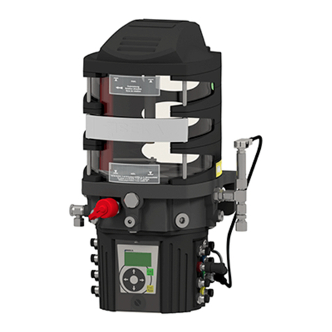
BEKA PICO-troniX1 Product guide

© BEKA 201 !9 All rights reserved
BAL2185_Grease_lubrication_pump_PICO_with_PICO-troniX1_-tronic_0519EN 10158410
...a product of
1
BEKA-MAX
Grease lubrication pump PICO
with integrated control unit
PICO-troniX1
PICO-tronic
Version -20105 9
Original operating
and
assembly manual

BAL2185_Grease_lubrication_pump_PICO_with_PICO-troniX1_-tronic_0519EN 10158410
...a product of
© BEKA 201 All !9 rights reserved
2
Table of contents
1. Technical data. . . . . . . . . . . . . . . . . . . . . . . . . . . . . . . . . . . . . . . . . . . . . . . . . . . . . . . . . . . . . . . . . . . . . . . . . . . 4
2. General safety instructions . . . . . . . . . . . . . . . . . . . . . . . . . . . . . . . . . . . . . . . . . . . . . . . . . . . . . . . . . . . . . . . . 5
2.1 Safety instructions. . . . . . . . . . . . . . . . . . . . . . . . . . . . . . . . . . . . . . . . . . . . . . . . . . . . . . . . . . . . . . . . . . . . 5
2.2 Qualification and training of staff. . . . . . . . . . . . . . . . . . . . . . . . . . . . . . . . . . . . . . . . . . . . . . . . . . . . . . . . . 5
2.3 Hazards in case of non-observance of the safety instructions . . . . . . . . . . . . . . . . . . . . . . . . . . . . . . . . . . 6
2.4 Obligations of the operator / user . . . . . . . . . . . . . . . . . . . . . . . . . . . . . . . . . . . . . . . . . . . . . . . . . . . . . . . . 6
2.5 Safety instructions for maintenance, inspection and assembly. . . . . . . . . . . . . . . . . . . . . . . . . . . . . . . . . . 6
2.6 Unauthorized modification and production of spare parts. . . . . . . . . . . . . . . . . . . . . . . . . . . . . . . . . . . . . . 7
2.7 Inadmissible modes of operation. . . . . . . . . . . . . . . . . . . . . . . . . . . . . . . . . . . . . . . . . . . . . . . . . . . . . . . . . 7
2.8 Electrostatic discharge . . . . . . . . . . . . . . . . . . . . . . . . . . . . . . . . . . . . . . . . . . . . . . . . . . . . . . . . . . . . . . . . 7
2.9 General hazard warning – residual risk. . . . . . . . . . . . . . . . . . . . . . . . . . . . . . . . . . . . . . . . . . . . . . . . . . . . 7
3. Intended use . . . . . . . . . . . . . . . . . . . . . . . . . . . . . . . . . . . . . . . . . . . . . . . . . . . . . . . . . . . . . . . . . . . . . . . . . . . . 8
4. Scope of warranty . . . . . . . . . . . . . . . . . . . . . . . . . . . . . . . . . . . . . . . . . . . . . . . . . . . . . . . . . . . . . . . . . . . . . . . 8
5. Transport and storage . . . . . . . . . . . . . . . . . . . . . . . . . . . . . . . . . . . . . . . . . . . . . . . . . . . . . . . . . . . . . . . . . . . . 9
6. Assembly instructions. . . . . . . . . . . . . . . . . . . . . . . . . . . . . . . . . . . . . . . . . . . . . . . . . . . . . . . . . . . . . . . . . . . . 9
6.1 Connection of lines . . . . . . . . . . . . . . . . . . . . . . . . . . . . . . . . . . . . . . . . . . . . . . . . . . . . . . . . . . . . . . . . . . . 9
6.2 Power connection . . . . . . . . . . . . . . . . . . . . . . . . . . . . . . . . . . . . . . . . . . . . . . . . . . . . . . . . . . . . . . . . . . . . 9
6.2.1 Connection diagram for devices with PICO-troniX1 and bayonet plug-type connection. . . . . . . . 10
6.2.2 Connection diagram for devices with PICO-troniX1 and Hirschmann plug-type connection . . . . 10
6.2.3 Connection diagram for devices with PICO-tronic . . . . . . . . . . . . . . . . . . . . . . . . . . . . . . . . . . . . 11
6.3 Assembly of pump elements . . . . . . . . . . . . . . . . . . . . . . . . . . . . . . . . . . . . . . . . . . . . . . . . . . . . . . . . . . . 12
6.3.1 Disassembly of a pump element. . . . . . . . . . . . . . . . . . . . . . . . . . . . . . . . . . . . . . . . . . . . . . . . . . 13
6.3.2 Assembly of a pump element . . . . . . . . . . . . . . . . . . . . . . . . . . . . . . . . . . . . . . . . . . . . . . . . . . . . 14
7. Start up . . . . . . . . . . . . . . . . . . . . . . . . . . . . . . . . . . . . . . . . . . . . . . . . . . . . . . . . . . . . . . . . . . . . . . . . . . . . . . . 15
7.1 Lubricants . . . . . . . . . . . . . . . . . . . . . . . . . . . . . . . . . . . . . . . . . . . . . . . . . . . . . . . . . . . . . . . . . . . . . . . . . 15
7.2 Filling with lubricant. . . . . . . . . . . . . . . . . . . . . . . . . . . . . . . . . . . . . . . . . . . . . . . . . . . . . . . . . . . . . . . . . . 15
7.2.1 Initial filling of devices with follow-up piston . . . . . . . . . . . . . . . . . . . . . . . . . . . . . . . . . . . . . . . . . 16
7.2.2 Filling of the device . . . . . . . . . . . . . . . . . . . . . . . . . . . . . . . . . . . . . . . . . . . . . . . . . . . . . . . . . . . . 18
7.3 Check of rotational direction . . . . . . . . . . . . . . . . . . . . . . . . . . . . . . . . . . . . . . . . . . . . . . . . . . . . . . . . . . . 19
7.4 Ventilation of the lubrication system . . . . . . . . . . . . . . . . . . . . . . . . . . . . . . . . . . . . . . . . . . . . . . . . . . . . . 20
8. Functional description. . . . . . . . . . . . . . . . . . . . . . . . . . . . . . . . . . . . . . . . . . . . . . . . . . . . . . . . . . . . . . . . . . . 20
8.1 Lubrication systems. . . . . . . . . . . . . . . . . . . . . . . . . . . . . . . . . . . . . . . . . . . . . . . . . . . . . . . . . . . . . . . . . . 20
8.1.1 Progressive lubrication systems . . . . . . . . . . . . . . . . . . . . . . . . . . . . . . . . . . . . . . . . . . . . . . . . . . 20
8.1.2 Multi-line lubrication systems . . . . . . . . . . . . . . . . . . . . . . . . . . . . . . . . . . . . . . . . . . . . . . . . . . . . 20
8.1.3 Mixed lubrication systems. . . . . . . . . . . . . . . . . . . . . . . . . . . . . . . . . . . . . . . . . . . . . . . . . . . . . . . 20
8.2 Setup of the device . . . . . . . . . . . . . . . . . . . . . . . . . . . . . . . . . . . . . . . . . . . . . . . . . . . . . . . . . . . . . . . . . . 22
8.3 Functional description of the device . . . . . . . . . . . . . . . . . . . . . . . . . . . . . . . . . . . . . . . . . . . . . . . . . . . . . 23
8.3.1 Functional description for version with follow-up piston . . . . . . . . . . . . . . . . . . . . . . . . . . . . . . . . 23
8.3.2 Functional description for version with agitator blade. . . . . . . . . . . . . . . . . . . . . . . . . . . . . . . . . . 24
8.4 Pump elements . . . . . . . . . . . . . . . . . . . . . . . . . . . . . . . . . . . . . . . . . . . . . . . . . . . . . . . . . . . . . . . . . . . . . 24
8.4.1 Pump elements PE-120 FV . . . . . . . . . . . . . . . . . . . . . . . . . . . . . . . . . . . . . . . . . . . . . . . . . . . . . 25
8.4.2 Pump elements PE-60 F, PE-120 F and PE-170 F. . . . . . . . . . . . . . . . . . . . . . . . . . . . . . . . . . . . 26
8.4.3 Order numbers of the pump elements for progressive lubrication systems . . . . . . . . . . . . . . . . . 27
8.4.4 Pump elements PE-5, PE-10, PE-15, PE-25 and PE-50 . . . . . . . . . . . . . . . . . . . . . . . . . . . . . . . 28
8.4.5 Code of the pump elements for multi-line lubrication systems . . . . . . . . . . . . . . . . . . . . . . . . . . . 29
8.5 Pressure limiting valves. . . . . . . . . . . . . . . . . . . . . . . . . . . . . . . . . . . . . . . . . . . . . . . . . . . . . . . . . . . . . . . 30
8.5.1 Pressure limiting valves with micro switch. . . . . . . . . . . . . . . . . . . . . . . . . . . . . . . . . . . . . . . . 30out
8.5.2 Pressure limiting valves with micro switch . . . . . . . . . . . . . . . . . . . . . . . . . . . . . . . . . . . . . . . . . . 31

© BEKA 201 !9 All rights reserved
BAL2185_Grease_lubrication_pump_PICO_with_PICO-troniX1_-tronic_0519EN 10158410
...a product of
3
8.6 Level monitoring . . . . . . . . . . . . . . . . . . . . . . . . . . . . . . . . . . . . . . . . . . . . . . . . . . . . . . . . . . . . . . . . . . . . 33
8.6.1 Level monitoring for devices with follow-up piston . . . . . . . . . . . . . . . . . . . . . . . . . . . . . . . . . . . . 33
8.6.2 Level monitoring for devices with agitator blade. . . . . . . . . . . . . . . . . . . . . . . . . . . . . . . . . . . . . . 33
9. Integrated control unit . . . . . . . . . . . . . . . . . . . . . . . . . . . . . . . . . . . . . . . . . . . . . . . . . . . . . . . . . . . . . . . . . . . 34
9.1 PICO-troniX1. . . . . . . . . . . . . . . . . . . . . . . . . . . . . . . . . . . . . . . . . . . . . . . . . . . . . . . . . . . . . . . . . . . . . . . 34
9.1.1 Functional description. . . . . . . . . . . . . . . . . . . . . . . . . . . . . . . . . . . . . . . . . . . . . . . . . . . . . . . . . . 35
9.1.2 Changing and adjusting the parameters. . . . . . . . . . . . . . . . . . . . . . . . . . . . . . . . . . . . . . . . . . . . 36
9.1.3 Operational mode of time-dependent cycle duration . . . . . . . . . . . . . . . . . . . . . . . . . . . . . . . . . . 36
9.1.4 Operational mode of time-dependent lubrication duration . . . . . . . . . . . . . . . . . . . . . . . . . . . . . . 37
9.1.5 Operation mode of revolution-dependent lubrication duration . . . . . . . . . . . . . . . . . . . . . . . . . . . 37
9.1.6 Function . . . . . . . . . . . . . . . . . . . . . . . . . . . . . . . . . . . . . . . . . . . . . . . . . . . . . . . 38Level monitoring
9.2 PICO-tronic . . . . . . . . . . . . . . . . . . . . . . . . . . . . . . . . . . . . . . . . . . . . . . . . . . . . . . . . . . . . . . . . . . . . . . . . 38
9.2.1 Functional description. . . . . . . . . . . . . . . . . . . . . . . . . . . . . . . . . . . . . . . . . . . . . . . . . . . . . . . . . . 40
9.2.2 Changing and adjusting the parameters. . . . . . . . . . . . . . . . . . . . . . . . . . . . . . . . . . . . . . . . . . . . 41
9.2.3 Operational mode of time-dependent cycle duration . . . . . . . . . . . . . . . . . . . . . . . . . . . . . . . . . . 41
9.2.4 Operational mode of pulse-dependent cycle duration . . . . . . . . . . . . . . . . . . . . . . . . . . . . . . . . . 42
9.2.5 Operational mode of time-dependent lubrication duration . . . . . . . . . . . . . . . . . . . . . . . . . . . . . . 43
9.2.6 Operational mode of pulse-dependent lubrication duration . . . . . . . . . . . . . . . . . . . . . . . . . . . . . 43
9.2.7 Operational mode of revolution-dependent lubrication duration . . . . . . . . . . . . . . . . . . . . . . . . . . 44
9.2.8 Function . . . . . . . . . . . . . . . . . . . . . . . . . . . . . . . . . . . . . . . . . . . . . 44System pressure monitoring
9.2.9 Function . . . . . . . . . . . . . . . . . . . . . . . . . . . . . . . . . . . . . . . . . . . . . . . . . . . . . . . 44Level monitoring
9.2.10 Function . . . . . . . . . . . . . . . . . . . . . . . . . . . . . . . . . . . . . . . . . . . . . . . . . . . 45Line break monitoring
9.2.11 Special function . . . . . . . . . . . . . . . . . . . . . . . . . . . . . . . . . . . . . . . . . . . . . 45External status signal
9.2.12 Special function . . . . . . . . . . . . . . . . . . . . . . . . . . . . . . . . . . 46Adjustment to operating conditions
9.2.13 Special function . . . . . . . . . . . . . . . . . . . . . . . . . . . . . . . . . . . . . . . . . . . . . . . . . . . . 47Cycle locked
9.2.14 Error . . . . . . . . . . . . . . . . . . . . . . . . . . . . . . . . . . . . . . . . . . . . . . . . . . . . . . . . . 47Lubrication deficit
10. Maintenance . . . . . . . . . . . . . . . . . . . . . . . . . . . . . . . . . . . . . . . . . . . . . . . . . . . . . . . . . . . . . . . . . . . . . . . . . . . 47
10.1 General maintenance . . . . . . . . . . . . . . . . . . . . . . . . . . . . . . . . . . . . . . . . . . . . . . . . . . . . . . . . . . . . . . . . 47
10.2 Lubricant change. . . . . . . . . . . . . . . . . . . . . . . . . . . . . . . . . . . . . . . . . . . . . . . . . . . . . . . . . . . . . . . . . . . . 48
10.3 Changing the integrated control unit . . . . . . . . . . . . . . . . . . . . . . . . . . . . . . . . . . . . . . . . . . . . . . . . . . . . . 48
11. Shutdown . . . . . . . . . . . . . . . . . . . . . . . . . . . . . . . . . . . . . . . . . . . . . . . . . . . . . . . . . . . . . . . . . . . . . . . . . . . . . 51
12. Disposal. . . . . . . . . . . . . . . . . . . . . . . . . . . . . . . . . . . . . . . . . . . . . . . . . . . . . . . . . . . . . . . . . . . . . . . . . . . . . . . 51
13. Troubleshooting . . . . . . . . . . . . . . . . . . . . . . . . . . . . . . . . . . . . . . . . . . . . . . . . . . . . . . . . . . . . . . . . . . . . . . . . 52
13.1 Signal indicators of the integrated control unit PICO-troniX1 . . . . . . . . . . . . . . . . . . . . . . . . . . . . . . . . . . 54
13.2 Signal indicators of the integrated control unit PICO-tronic. . . . . . . . . . . . . . . . . . . . . . . . . . . . . . . . . . . . 55
14. Spare part list and drawing . . . . . . . . . . . . . . . . . . . . . . . . . . . . . . . . . . . . . . . . . . . . . . . . . . . . . . . . . . . . . . . 56
15. Dimensional drawing . . . . . . . . . . . . . . . . . . . . . . . . . . . . . . . . . . . . . . . . . . . . . . . . . . . . . . . . . . . . . . . . . . . . 57
15.1 Dimensional drawing for devices with integrated control unit PICO-troniX1 . . . . . . . . . . . . . . . . . . . . . . . 57
15.2 Dimensional drawing for devices with integrated control unit PICO-tronic . . . . . . . . . . . . . . . . . . . . . . . . 58
16. Code . . . . . . . . . . . . . . . . . . . . . . . . . . . . . . . . . . . . . . . . . . . . . . . . . . . . . . . . . . . . . . . . . . . . . . . . . . . . . . . . . 59
16.1 Code for devices with integrated control unit PICO-troniX1 . . . . . . . . . . . . . . . . . . . . . . . . . . . . . . . . . . . 59
16.2 Code for devices with integrated control unit PICO-tronic. . . . . . . . . . . . . . . . . . . . . . . . . . . . . . . . . . . . . 60
16.3 Code for integrated control unit PICO-troniX1. . . . . . . . . . . . . . . . . . . . . . . . . . . . . . . . . . . . . . . . . . . . . . 61
16.4 Code for integrated control unit PICO-tronic . . . . . . . . . . . . . . . . . . . . . . . . . . . . . . . . . . . . . . . . . . . . . . . 62
17. Declaration of incorporation . . . . . . . . . . . . . . . . . . . . . . . . . . . . . . . . . . . . . . . . . . . . . . . . . . . . . . . . . . . . . . 63
18. For your notes . . . . . . . . . . . . . . . . . . . . . . . . . . . . . . . . . . . . . . . . . . . . . . . . . . . . . . . . . . . . . . . . . . . . . . . . . 66
19. Details of the manufacturer. . . . . . . . . . . . . . . . . . . . . . . . . . . . . . . . . . . . . . . . . . . . . . . . . . . . . . . . . . . . . . . 68

BAL2185_Grease_lubrication_pump_PICO_with_PICO-troniX1_-tronic_0519EN 10158410
...a product of
© BEKA 201 All !9 rights reserved
4
1. Technical data
General:
Delivery rate per stroke and outlet: . . . . . . . . . . . . . . depending on pump element (see chapter 8.4 „Pump elements“)
No. of outlets: . . . . . . . . . . . . . . . . . . . . . . . . . . . . . . . . . . . pump elements PE-5 to PE-50: . . . . . . . . . . . . . . . . max. 8
. . . . . . . . . . . . . . . . . . . . . . . . . . . . . . . . . . . . . . . . . . . . . . pump elements PE-60 F to PE-170 F:. . . . . . . . . . . max. 2
Pressure connection:. . . . . . . . . . . . . . . . . . . . . . . . . Ø4 mm, Ø6 mm or thread M10x1 (multi-line lubrication systems)
. . . . . . . . . . . . . . . . . . . . . . . . . . . . . . . . . . . . . . . . Ø6 mm, Ø8 mm or thread G1/4" (progressive lubrication systems)
Lubricant: . . . . . . . . . . . . . . . . . . . . . . . . . . . . . . . . . . . . . . . . . . . . . . . . . . . . . . . . . . . . . . . . . greases up to NLGI cl. 2
. . . . . . . . . . . . . . . . . . . . . . . . . . . . . . . . . . . . . . . . . . . . . . . . . . . . . . . . . . . . . (greases with solids content on request)
Operating pressure:. . . . . . . . . . . . . . . . . . . . . . . . . . . . . . . . . . . . . . . . . . max. 200 bar (multi-line lubrication systems)
. . . . . . . . . . . . . . . . . . . . . . . . . . . . . . . . . . . . . . . . . . . . . . . . . . . . . . . max. 300 bar (progressive lubrication systems)
Pressure limiting valve: . . . . . . . . . . . . . . . . . . . . . . . . . . . . . . . . . . . . set to 290 bar (progressive lubrication systems)
Operating temperature: . . . . . . . . . . . . . . . . . . . . . . . . . . . . . . . . . . . . . . . . . . . . . . . . . . . . . . . . . . . -35°C up to +70°C
Transport and storage temperature: . . . . . . . . . . . . . . . . . . . . . . . . . . . . . . . . . . . . . . . . . . . . . . . . . -40°C up to +70°C
Reservoir material: . . . . . . . . . . . . . . . . . . . . . . . . . . . . . . . . . . . . . . . . . . . . . . . . . . . . . . . . . . . . . . plastic, transparent
Reservoir size: . . . . . . . . . . . . . . . . . . . . . . . . . . . . . . . . . . . . . . . . . . . . . . . . . . . . . . . . . . . . . . . . . . . . . . . . . . . . . 1,5 l
Effective volume:. . . . . . . . . . . . . . . . . . . . . . . . . . . . . . . . . . . . . . . . . . . . . . . . . . . . . . . . . . . . . . . . . . . . . . . . . . . . 1,2 l
Installation position: . . . . . . . . . . . . . . . . . . . . . . . . . . . . . . . . . . . . . . . . . . . . . . optional (version with follow-up piston)
. . . . . . . . . . . . . . . . . . . . . . . . . . . . . . . . . . . . . . . . reservoir in a vertically upright position (version with agitator blade)
Level monitoring:. . . . . . . . . . . . . . . . . . . . . . . . . . . . . . . . . with, installed in pump body (version with follow-up piston)
. . . . . . . . . . . . . . . . . . . . . . . . . . . . . . . . . . . . . . . . . . . . . . . . . . . . . . . . . . . . . . . . without (version with agitator blade)
Rotational direction of the agitator blade:. . . . . . . . . . . . . . . . . . . . . . . . . . . . . . . . . . . . . . . . . . . . . . . . . . . . . clockwise
Degree of protection:. . . . . . . . . . . . . . . . . . . . . . . . . . . . . . . . . . . . . . . . . . . . . . . . . . . . . . . . . . . . . . . . . . . . . . . . IP 65
Weight: . . . . . . . . . . . . . . . . . . . . . . . . . . . . . . . . . . . . . . . . . . . . . . . . . . . . . . . . . . . . . . . . . . . . . . . . . . . approx. 4,8 kg
. . . . . . . . . . . . . . . . . . . . . . . . . . . . . . . . . . . . (without pump element, without grease filling, depending on equipment)
Motor:
Supply voltage: . . . . . . . . . . . . . . . . . . . . . . . . . . . . . . . . . . . . . . . . . . . . . . . . . . . . . . . . . . . . . . . . . . . . . 12 or 24 V DC
Current load max.:. . . . . . . . . . . . . . . . . . . . . . . . . . . . . . . . . . . . . . . . . . . . . . . . . . . . . . . . . . . . . . . . . . . . 6,3 A at 12 V
. . . . . . . . . . . . . . . . . . . . . . . . . . . . . . . . . . . . . . . . . . . . . . . . . . . . . . . . . . . . . . . . . . . . . . . . . . . . . . . . . . . 3,3 A at 24 V
Pump speed:. . . . . . . . . . . . . . . . . . . . . . . . . . . . . . . . . . . . . . . . . . . . . . . . . . . . . . . . . . . . . . . . . . . . . . . . . . . . 15 r.p.m
Integrated control unit:
Supply voltage: . . . . . . . . . . . . . . . . . . . . . . . . . . . . . . . . . . . . . . . . . . . . . . . . . . . . . . . . . . . . . . . . . . . . . . . . 10 to 60 V
Current load max.: . . . . . . . . . . . . . . . . . . . . . . . . . . . . . . . . . . . . . . . . . . . . . . . . . . . . . . . . . . . . . . . . . . . . . . . . . . 6,0 A
Output for signal lamp:. . . . . . . . . . . . . . . . . . . . . . . . . . . . . . . . . . . . . . . . . . . . . . . . . . . . . . . . . . . . . . . . . . . . . . . 0,4 A
Fuse (not included in device): . . . . . . . . . . . . . . . . . . . . . . . . . . . . . . . . . . . . . . . . . . . . . . . . . . . . . . . . . . . . . . . . . 6,3 A
. . . . . . . . . . . . . . . . . . . . . . . . . . . . . . . . . . . . . . . . . . . . . . . . . . . . . . . . . . . . . . . . . . . . . . . . . . (5x20) medium time lag
The issubsequently calleda .greaselubrication pumpPICO device

© BEKA 201 !9 All rights reserved
BAL2185_Grease_lubrication_pump_PICO_with_PICO-troniX1_-tronic_0519EN 10158410
...a product of
5
2. Generalsafety instructions
Everybody who is in charge of the assembly, start-up, maintenance and operation of the device must read these
instructions carefully prior to assembly and start-up of the device at the machine! Furthermore, this manual must always
beavailable atthe siteof operation!
Basicinstructions forsetup, operationand maintenancecan befound below.
2.1 Safetyinstructions
Observe the general safety instructions within this key chapter as well as the special safety instructions in other chapters
ofthis operatingand assemblymanual.
Warning ofelectrical voltage.
Safety instructions, which might cause hazards to persons in case of non-observance, are marked with the
generaldanger symbol.
Thissymbol warnsof hotsurfaces.
Warning ofsuspended loads.
Warning of material damage due to electrostatic discharge! Marks potential risks which may result in material
damage,if notavoided.
This heading is used if improper or general non-observance of the operating and assembly
manual,instructions, specifiedworkflow andthe likemight resultin damage.
Thisterm isused topoint outparticular details.
Instructions and notes directly attached to the device have to be strictly observed and kept in readable
condition!
2.2 Qualificationand trainingof staff
The staff in charge of operation, maintenance, inspection and assembly have to be qualified accordingly.
Competence,responsibilities andsupervision ofstaffmust beclearly definedby theoperator. Incase thestaff
does not have the necessary knowledge it has to be instructed and trained accordingly. The operator is
obligedto ensurethat thestafffully understandsthe contentsof thisuser information.
Caution!
Notice!

BAL2185_Grease_lubrication_pump_PICO_with_PICO-troniX1_-tronic_0519EN 10158410
...a product of
© BEKA 201 All !9 rights reserved
6
2.3 Hazardsin caseof non-observanceof thesafety instructions
Results of of the can be , for the environment andnon-observance safety instructions hazards to persons
the device. Non-observance of the safety instructions may result in the loss of any liability claims. The non-
observancecould morespecifically resultin thefollowing hazards(for example):
·Failureof importantdevice functions.
·Failureof prescribedmethods regardingmaintenance andrepair.
·Dangerto personsby electrical,mechanical andchemical effects.
·Dangerto theenvironment byleakage ofhazardous substances.
2.4 Obligationsof theoperator /user
·If movable, rotating, hot or cold parts of the device bear risks, the customer must protect these parts
againstcontact. Thisprotectionmust notbe removed.
·Any leakages of hazardous substances must be drained in a way that no risks for persons or the
environmentarise. Pleasealso referto thedata orsafety datasheetsof therespective manufacturers.
·Observeall legalprovisions.
·Hazardsdue toelectricity areto beexcluded.
·Examination of pipes and hoses regarding safe provision, use, proper assembly and function has to be
carriedout accordingto regionallyapplicable directives.Inspection intervalsmay notbe exceeded.
·Defectivepipes orhoses mustbe replacedimmediately andprofessionally.
·Hydraulic hoses and polyamide pipes are subject to natural aging and have to be exchanged in regular
intervalsaccording tothe manufacturer'sspecifications.
·Asafetydata sheetof thecurrently usedlubricant mustbeprovided atthe device.
·Observethe universallyvalid Ordinanceon HazardousSubstances inits latestversion.
2.5 Safetyinstructions formaintenance, inspectionand assembly
All and may only be carried out by who ismaintenance, inspection assembly work qualified personnel
sufficientlyinformed bythoroughreading ofthe userinformation.
Any work complete standstill pressurelessat the device may generally only be carried out at and in as
well as . Furthermore, appropriate (gogglesdisconnected condition personal protective equipment
among others) is necessary. The shutdown procedure of the device as described in the manual must be
strictlyfollowed.
Secure the device against intentional or unintentional recommissioning during maintenance or repair. All
safety and protection arrangements have to be put back in place again immediately after completion of the
work.
Environmentally hazardous media must be disposed of professionally and according to the relevant legal
provisions. and have to be cleaned before maintenance. Please wearPolluted contaminated surfaces
protective equipment to that purpose. See the lubricant manufacturers' safety data sheets hereto,
respectivelythe datasheets providedby themanufacturers ofauxiliaries andworkingmaterials.

© BEKA 201 !9 All rights reserved
BAL2185_Grease_lubrication_pump_PICO_with_PICO-troniX1_-tronic_0519EN 10158410
...a product of
7
Check the surface temperature of the device as a possible heat transfer bears the . Wear heatrisk of burns
resistantprotective gloves!
Openflame andfire arestrictly forbiddenduring maintenance,inspection and repairdue tofire hazard.
2.6 Unauthorizedmodification andproduction ofspare parts
Modification, repair and alterations of the device are only accepted after manufacturer feedback. Original
spare parts safety.and authorized accessories from the manufacturer contribute to The use of other parts
can result in the loss of any liabilities for the resulting consequences. BEKAdoes not assume liability for parts
thatare retrofitby theoperator.
2.7 Inadmissiblemodes ofoperation
Operational safety of the device is only guaranteed when it is appropriately applied as indicated in the operating and
assemblymanual. Neverexceed orfall belowthe limitvalues, asstatedin thetechnical data.
2.8 Electrostaticdischarge
Avoid electrostatic discharge! There are electronic components integrated into the devices which might be
destroyed by electrostatic discharge. Observe the safety precautions against electrostatic discharge
according to DIN EN 61340-5-1/-3. Ensure that the environment (persons, workplace and packing) is well
groundedwhen handlingthese devices.
2.9 Generalhazard warning– residualrisk
All components are designed according to valid regulations for the construction of technical systems with
regard to operational safety and accident prevention. Nevertheless, their use can lead to hazards for the user
or third parties as well as other technical facilities. Therefore, the device may only fulfill its intended purpose in
a . This has to happen in adherence to the relevant safetytechnically perfect and faultless condition
regulations as well as the operating and assembly manual. the device and its attachment partsInspect
regularly check damage leakages. Liquids escape under high pressureand them for possible or could
frompressurized componentswhich becomeleaky.

BAL2185_Grease_lubrication_pump_PICO_with_PICO-troniX1_-tronic_0519EN 10158410
...a product of
© BEKA 201 All !9 rights reserved
8
3. Intendeduse
Thedevice isonly approvedfor the or .industrial commercialuse
Onlyoperate thedevice ifit isinstalled in/atanother machineandoperated togetherwith it.
Onlylubricants whichcomply withthe machinemanufacturer's specificationsmay beconveyed.
The device must only be used according to the technical data (see chapter 1 „Technical data”).The.
values may never exceed or fall below the values mentioned in the technical data. Never operate
thedevice withoutlubricant.
Unauthorized modifications not permittedof the device are . BEKA is not liable for personal injury or damage of
machineresulting thereof.
Theintended usealso includes:
·payingattention toall chaptersand notesin theoperating andassemblymanual.
·carryingout allmaintenance work.
·observing work safety accidentpreventionallrelevant instructionsfor and duringall lifecycles ofthe device.
·having the necessary professional training and authorization of your company to operate the device and to carry out
thenecessary workon thedevice.
Anotheruse ora usebeyond thisscope isdeemedimproper.
4. Scopeof warranty
Warranties regarding operational safety, reliability and performance will only be granted by the manufacturer if the device
isused accordingto theregulations andunder thefollowing conditions:
·Assembly, connectionand maintenanceare onlycarried outby authorizedandqualified staff.
·Thedevice isonly usedaccording tothe operatingand assemblymanual.
·Neverexceed orfall belowthe limitvalues asdefined inthetechnical data.
·Modificationsand repairsat thedevice mayonly bedone byBEKA.
Guaranty and warranty will expire for any damage of the device caused by improper lubricant (e.g.
wearof piston,piston jamming,blockades, brittledsealings etc.).
BEKAwill generally not accept guaranty claims for any damage caused by lubricants, even though
those have been laboratory tested and released by BEKA, as such damage (e.g. by over-stored or
incorrectlystored lubricants,batch fluctuations,etc.) cannotbe verifiedor reconstructedlater.
Caution!
Caution!
Caution!

© BEKA 201 !9 All rights reserved
BAL2185_Grease_lubrication_pump_PICO_with_PICO-troniX1_-tronic_0519EN 10158410
...a product of
9
5. Transportandstorage
Usesuitable liftingdevices fortransport.
Donot the deviceor exposeit tothrow shocks.
Securethe deviceagainst topplingdown orslipping duringtransport.
Observe all valid safety and accident prevention regulations for the transport. Wear suitable protective
equipment Keep adequate distance to suspended loads.if necessary. The transport help or the elevating
devicemust havethe adequatecarrying capacity.
When storing the device pay attention that the storage area is cool and dry in order to avoid
corrosionof theindividual partsof thedevice.
Observe the storability of the contained lubricant for devices which are filled with lubricant.
Exchangethe lubricantwhen itis over-stored(separation ofoil andsoap).
6. Assemblyinstructions
Check the device for possible transport damage and for completeness before the assembly.Any installed equipment for
transportationsafety hasto beremoved.
Comply with the following conditions when assembling a complete machine from this device and other
components.Mind aproper andeco-friendly assemblywithout impairmentof persons'healthand safety:
Devices with agitator blade have to be assembled balanced at both sides at the setup location and the reservoir has to
be in an upright position notin order to ensure a safe operation! Devices with follow-up piston do have to be assembled
in a vertically upright position. Observe the information on the fastening holes given in the dimensional drawing. When
selecting the set-up location, please mind that the device should be protected against ambient and mechanic influences.
Ensurefull access,e.g. forfilling withlubricant.
Specialmeasures concerningnoise preventionor oscillationreduction donot havetobe taken.
6.1 Connectionof lines
·Professionallayout!
·Whenusing pipes,observe thatthey areclean, seamlessand ofprecisionsteel!
·Assemblethe pipesprofessionally andfree fromdistortion!
·Payattention topressure tightnessof fittings!
·Allcomponents mustbe approvedfor max.operating pressure(see chapter1.„Technical data“).
6.2 Powerconnection
·Powersupply mustbe doneby aprofessional electrician!
·Electricaldevice componentsmust bewired professionally!
·Comparevoltage detailswith theexisting mainsvoltage!
·Equipotentialbonding mustbe doneprofessionally bythe operatorvia anaccordingground connection!
·Wirethe deviceaccording tothe connectiondiagram!
Notice!

BAL2185_Grease_lubrication_pump_PICO_with_PICO-troniX1_-tronic_0519EN 10158410
...a product of
© BEKA 201 All !9 rights reserved
10
Devices with integrated control unit PICO-troniX1 can be supplied with bayonet plug-type
connection Hirschmann plug-type connection connection plug 10 m longor . The and a
connectioncable areincluded inthe scopeof deliveryfor bothversions.
Devices with integrated control unit PICO-tronic are supplied with two Hirschmann plug-type
connections connection plug for the voltage connection 10 m long. The (see fig. 40) and a
connection cable connection plug for the additionalare included in the scope of delivery. The
equipment without connection cable(see fig. 40) is supplied . If you need a connection cable, it
hasto beordered (order numberson request).separately
Thefollowing listedconnection diagramsare validfor standardversions.
Otherconnection diagramsmay bevalid forspecial versions.These areavailable onrequest.
6.2.1 Connectiondiagram fordevices withPICO-troniX1 andbayonet plug-typeconnection
Fig.1:
6.2.2 Connectiondiagram fordevices withPICO-troniX1 andHirschmann plug-typeconnection
Fig.2:
Notice!
+Ub
Mass
green
red
black
orange
brown
Push-button
for intermediate
lubrication
Lampe red
Lampe green
Mass
+Ub
brown
black
red
green
orange
Lamp red
Lamp green
Push-button for
intermediate lubrication
PIN 7
PIN 5
PIN 2
PIN 1
PIN 6

© BEKA 201 !9 All rights reserved
BAL2185_Grease_lubrication_pump_PICO_with_PICO-troniX1_-tronic_0519EN 10158410
...a product of
11
6.2.3 Connectiondiagram fordevices withPICO-tronic
Fig.3:
brown
green
Lamp green
red
Lamp red
-+
-+
white
grey
min.
max.
Cycle locked
orange
black
Push-button for intermediate
lubrication
+Ub
Mass
3-notch switch for
adjustment to operating
conditions
External
signal
lamp
optional
black
brown
blue
black
grey
brown
free
black
brown
blue
Operational mode of
pulse-dependent cycle
duration (e.g. proximity
switch at lubrication pinion)
Operational mode of pulse-dependent
lubrication duration (e.g. proximity switch
at progressive distributor)
System pressure monitoring
(Micro switch at pressure
limiting valve)
Line break monitoring
(at progressive distributor)
brown
black
blue
Status signal
External lamp
Operational release relay
optional
optional

BAL2185_Grease_lubrication_pump_PICO_with_PICO-troniX1_-tronic_0519EN 10158410
...a product of
© BEKA 201 All !9 rights reserved
12
6.3 Assemblyof thepump elements
Differentpump elementscanbe installedinto thedevice (seechapter 8.4„Pump elements“).
Fig.4:
Thepump elementsPE-60 F,PE-120 F,PE-170 FandPE-120 FVcan bescrewed intothe outlets4 and10 (seefig. 4).
Thepump elementsPE-5, PE-10,PE-15, PE-25and PE-50canbe screwedinto theoutlets 1to 3and 5to9 (seefig. 4).
Remove the screw plug with an Allen keyAF 10 (outlets 4 and 10, see fig. 4) or AF 6 (outlets 1 to 3 and 5 to 9, see fig. 4)
fromthe outletinto whichyou wantto screwin thepump element.
Exchangethe sealingof thepump elementin orderto avoidthatdamaged sealingsare reused.
When the pump elements PE-5 to PE-50 are ordered separately, the sealing is not included in the
scope of delivery and has to be ordered separately if needed (see chapter 8.4.5 „Code of the pump
elementsfor multi-linelubrication systems“).
Inthe following,the disassemblyand assemblyof thepump elementsisdescribed atthe examplePE-120 F.
Notice!
1
2
3
4
5
10
6
7
8
9

© BEKA 201 !9 All rights reserved
BAL2185_Grease_lubrication_pump_PICO_with_PICO-troniX1_-tronic_0519EN 10158410
...a product of
13
6.3.1 Disassemblyof apump element
A) Disconnectthe devicefrom thepower supply(pos. 1,see fig.5)and secureit againstrecommissioning.
Fig.5:
B) Unscrewthe pumpelement.
Fig.6:
Makesure thatthe pistonof thepump elementdoes notremain inthe pumphousing!
Ifthe pistonremains inthe pumphousing, theeccentric maybedamaged orthe devicemight block.
Caution!
1
AF 24

BAL2185_Grease_lubrication_pump_PICO_with_PICO-troniX1_-tronic_0519EN 10158410
...a product of
© BEKA 201 All !9 rights reserved
14
6.3.2 Assemblyof apump element
C) Exchange the sealing, screw in the pump element and adjust it until the desired position has been reached.
Tightenthepump elementwith thebelow indicatedtightening torque(see fig.7).
Fig.7:
Tightenthepump elementsPE-5 toPE-50 witha tighteningtorque of20 Nm±10%.
Tighten the pump elements PE-60 F to PE-170 F and PE-120 FV with a tightening torque of
45Nm ±10%.
D) Reconnectthe deviceto thepower supply(pos. 1,see fig.8)
Fig.8:
Initiatea trialrun andlet thedevice operatewith openoutlets untilthe lubricantleaks outbubble-free.
Notice!
AF 24
1

© BEKA 201 !9 All rights reserved
BAL2185_Grease_lubrication_pump_PICO_with_PICO-troniX1_-tronic_0519EN 10158410
...a product of
15
7. Startup
7.1 Lubricants
Thedevice isdesigned forstandard multi-purposegreases upto NLGIcl.2.
·Uselubricants withhigh-pressure additives.
·Onlyuse lubricantsof thesame soapingcriteria.
·Donot useany lubricantswith solidscontent (lubricantswith solidscontenton request,e.g. graphiteor MoS2)
7.2 Fillingwith lubricant
·Fillthe lubricantreservoir withclean lubricantat thefilling nippleora fillingconnection!
·Observe the machine manufacturer's lubricant details! Only use lubricants according to machine manufacturer's
specifications!
·Collectleaking lubricantin asuitable reservoirand disposeit professionally!
·Observethe safetydata sheetof thelubricant manufacturer!
·Thelubricant viscositychanges withthe operatingtemperature.
·Checkthe levelseveral timesin equalintervals duringthe firsthoursof operationand refilllubricant, ifnecessary.
·Payattention toutmost cleannesswhen refillingthe reservoir!
By default, you receive the device with a basic filling. The procedure for filling devices with basic
fillingcan befound inchapter 7.2.2„Filling ofthe device“.
If the device has no basic filling, observe the procedure for the initial filling for devices with follow-up
piston which is described in chapter 7.2.1 „Initial filling of devices with follow-up piston“. You can
proceed as described in chapter 7.2.2 „Filling of the device“ for the initial filling of devices with
agitatorblade.
Caution!

BAL2185_Grease_lubrication_pump_PICO_with_PICO-troniX1_-tronic_0519EN 10158410
...a product of
© BEKA 201 All !9 rights reserved
16
7.2.1 Initialfilling ofdevices withfollow-up piston
Use a standard grease pump (hand lever grease gun) for the initial filling of the device with follow-up piston and fill the
devicevia thecone-type zerk.
Pay attention to utmost cleanliness at the initial filling of the device. Only fill in clean lubricant. When
dirt particles get into the device, the pistons of the pump elements can wear, which results in the
destruction of the pump elements. The dirt particles can also get into the lubrication system and can
cloglines orconnected progressivedistributors.
A) Connect the device according to the connection diagram (see chapter 6.2 „Power connection“) and turn it around
sothat thereservoir coverpoints down(see fig.9).
Fig.9:
B) Removethe overfillprotection andthe protectivecap ofthe cone-typezerk(see fig.10).
Fig.10:
Caution!
Overfill protection
Cone-type zerk with
protective cap
Overfill protection removed!
Protective cap removed!

© BEKA 201 !9 All rights reserved
BAL2185_Grease_lubrication_pump_PICO_with_PICO-troniX1_-tronic_0519EN 10158410
...a product of
17
C) Takethe deviceinto operation.
Operatethe fillinggun untillubricant leaksout visiblyat theoutlet(see fig.12).
Connect the filling gun to the cone-type zerk and fill the device until lubricant leaks out at the opening of the overfill
protection(see fig.11).
Fig.11: Fig. 12:
D) Screwthe overfillprotection backin andtighten itwith atighteningtorque of15 Nm±10%.
Fig.13:
E) Turn the device around again and fill it up to the maximum level (see fig. 15). Put the protective cap back on the
cone-typezerk afterfinishing thefilling process.
Fig.14:
Avoid overfilling the device; otherwise lubricant
might leak out which can cause environmental
damage!
Caution!
Level max.
Overfill protection
Cone-type zerk
Lubricant leakage
at the opening of
the overfill protection Lubricant
Filling gun

BAL2185_Grease_lubrication_pump_PICO_with_PICO-troniX1_-tronic_0519EN 10158410
...a product of
© BEKA 201 All !9 rights reserved
18
7.2.2 Fillingof thedevice
Pay attention to utmost cleanliness when filling the device. Only fill in clean lubricant. When dirt
particles get into the device, the pistons of the pump elements can wear, which results in the
destruction of the pump elements. The dirt particles can also get into the lubrication system and can
cloglines orconnected progressivedistributors.
Avoid overfilling the device; otherwise lubricant might leak out which can cause environmental
damage!
A) Fillingvia thecone-type zerkwith afilling gun(standard)
Remove the protective cap of the existing cone-type zerk, connect a suitable filling gun (manually operated or pneumatic)
to this one and fill the device up to the maximum level (see fig. 15). Put the protective cap back on the cone-type zerk after
finishingthe fillingprocess.
Fig.15:
B) Fillingvia thefilling connectionG1/4
Remove the cone-type zerk and replace it by a filling connection G1/4 (order no.: 21590061006). Connect a suitable filling
pumpto thefilling connectionG1/4 andfill thedevice uptothe maximumlevel (seefig. 16).
Fig.16:
Level max.
Cone-type zerk
Caution!
Level max.

© BEKA 201 !9 All rights reserved
BAL2185_Grease_lubrication_pump_PICO_with_PICO-troniX1_-tronic_0519EN 10158410
...a product of
19
C) Fillingvia thefilling setPICO Fill
The filling set PICO Fill (order no.: 208103027) has been developed for an easy and quick filling of the device. It consists
ofa fillingconnection M20x1,5(order no.:21520152) anda fillinggun(order no.:208103026).
Remove the screw plug from the outlet 4 or 10 (see fig. 4 in chapter 6.3 „Assembly of the pump elements“) and screw in
thefilling connectionM20x1,5.
Operatethe fillinggun untilthe lubricantleaks outvisibly attheoutlet (approx.10 mm,see fig.17).
Connectthe fillinggu the fillingconnection M20x1,5and fillthe deviceupto themaximum level.nto
Remove the filling connection M20x1,5 after finishing the filling process and screw the screw plug, which had been
removedearlier, backin.
Fig.17:
7.3 Checkof rotationaldirection ofthe device
·Compare the rotational direction of the agitator blade with the directional arrow on the level sticker (see fig. 18) for
deviceswith agitatorblade.
·Checkthe electricalconnections ofthe deviceat awrong rotationaldirectionand changethese ifnecessary.
The and the will be when they are operated in themotor damaged wrong rotationaldevice
directionfor alonger time!
Fig.18:
Level max.
10 mm
Lubricant
Filling gun
Caution!
Directional arrow
on level sticker

BAL2185_Grease_lubrication_pump_PICO_with_PICO-troniX1_-tronic_0519EN 10158410
...a product of
© BEKA 201 All !9 rights reserved
20
7.4 Ventilationof thelubrication system
·Ventilatethe wholelubrication systemon firststart-up andafter eachlubricantchange!
·Ventilationis doneby operatingthe systemin pressurelesscondition andwithopen systemoutlets!
·Operatethe deviceuntil lubricantescapes fromthe pressureconnection withoutairinclusions.
8. Functionaldescription
8.1 Lubricationsystems
The device can be used for the lubrication in progressive lubrication systems, multi-line lubrication systems or in mixed
lubrication systems. The lubrication systems are also controlled by the integrated control unit PICO-troniX1 or PICO-
tronic.
Up to two lubrication circuits, which are independent from each other, can be connected the device at installation into ato
progressivelubrication system.
Upto 8lube pointscan besupplied withlubricant whenthe deviceis usedin amulti-line lubricationsystem.
Bothsystems canalso becombined withthe device(mixed lubricationsystem).
8.1.1 Progressivelubrication systems
Progressivelubrication systemsare lubricationsystems whichcan processlubricants upto NLGI cl.2.
A progressive lubrication system mainly consist of a lubrication pump and one or several progressive distributors. Thes
lubrication pump supplies the lubricant into a main distributor. This distributor distributes the lubricant in the correct
relationto thesecondary distributors,which redistributethe lubricantto thelubepoints.
If one lube point does not take any lubricant from the distributor, it blocks. Pressure builds up in the system by this. The
system pressure is limited to 290 bar by a pressure limiting valve at the pump element (see fig. 19, pos. 11 and pos. 12).
Thesystem isthereby protectedfrom beingdamaged bytoo highpressure.
8.1.2 Multi-linelubrication systems
Multi-linelubrication systemsare lubricationsystem which canprocess lubricantsup toNLGI cl. 2.s
A multi-line lubrication system mainly consists of a lubrication pump and several lubrication lines which are connected
directly to the lube points. Each lube point requires its own pump element at the lubrication pump (see fig. 19, pos. 3 up to
pos.10).
8.1.3 Mixedlubrication systems
Aprogressive lubrication system and a multi-line lubrication system can be connected the device at the same time; thisto
iscalled amixed lubricationsystem.
One lubrication circuit with progressive distributors can each be connected the pump elements pos. 1 and pos. 2 (seeto
fig.19). Onelube pointcan eachbe connected thepump elementspos. 3to pos.10 (seefig. 19).to
This manual suits for next models
2
Table of contents
Other BEKA Water Pump manuals

BEKA
BEKA BEKA-MAX GIGA Product guide

BEKA
BEKA HPM-2S Product guide

BEKA
BEKA BEKA-MAX OC-1 User manual

BEKA
BEKA EP-1 Product guide

BEKA
BEKA HPM-3 2583 Series Product guide

BEKA
BEKA ZEPTO Product guide

BEKA
BEKA Stream H Product guide

BEKA
BEKA HAMAX System 2 User manual

BEKA
BEKA HAMAX Kompakt M14 Product guide

BEKA
BEKA HAMAX 2 Product guide