BEKA HPM-3 2583 Series Product guide

Page 1 © BEKA 2018 All rights reserved!
...a product of
Grease lubrication pump
HPM-3
Code 2583 …
Revision 01-2018
Original operating
and
assembly manual
BAL2583_Grease_lubrication_pump_HPM-3_0118EN

Page 2 © BEKA 2018 All rights reserved!
...a product of
Table of contents
1.Technical data ................................................................................................................................................................................3
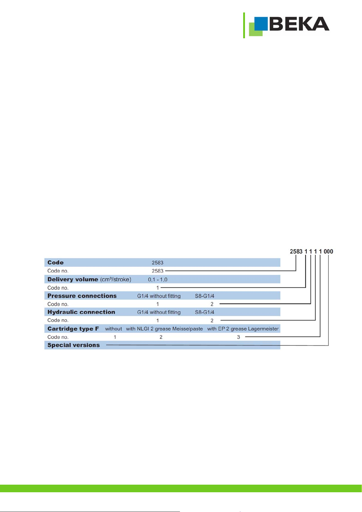
2.Code ...............................................................................................................................................................................................3
2.1Cartridges ..................................................................................................................................................................................3
3.General safety instructions .............................................................................................................................................................4
3.1Safety instructions .....................................................................................................................................................................4
3.2Qualification and training of staff ...............................................................................................................................................4
3.3Hazards in case of non-observance of the safety instructions ..................................................................................................5
3.4Obligations of the operator / user ..............................................................................................................................................5
3.5Safety instructions for maintenance, inspection and assembly .................................................................................................5
3.6Unauthorized modification and production of spare parts .........................................................................................................5
3.7Inadmissible modes of operation...............................................................................................................................................6
3.8General hazard warning – residual risk .....................................................................................................................................6
4.Intended use...................................................................................................................................................................................7
5.Scope of warranty...........................................................................................................................................................................7
6.Transport and storage ....................................................................................................................................................................7
7.Assembly instructions.....................................................................................................................................................................8
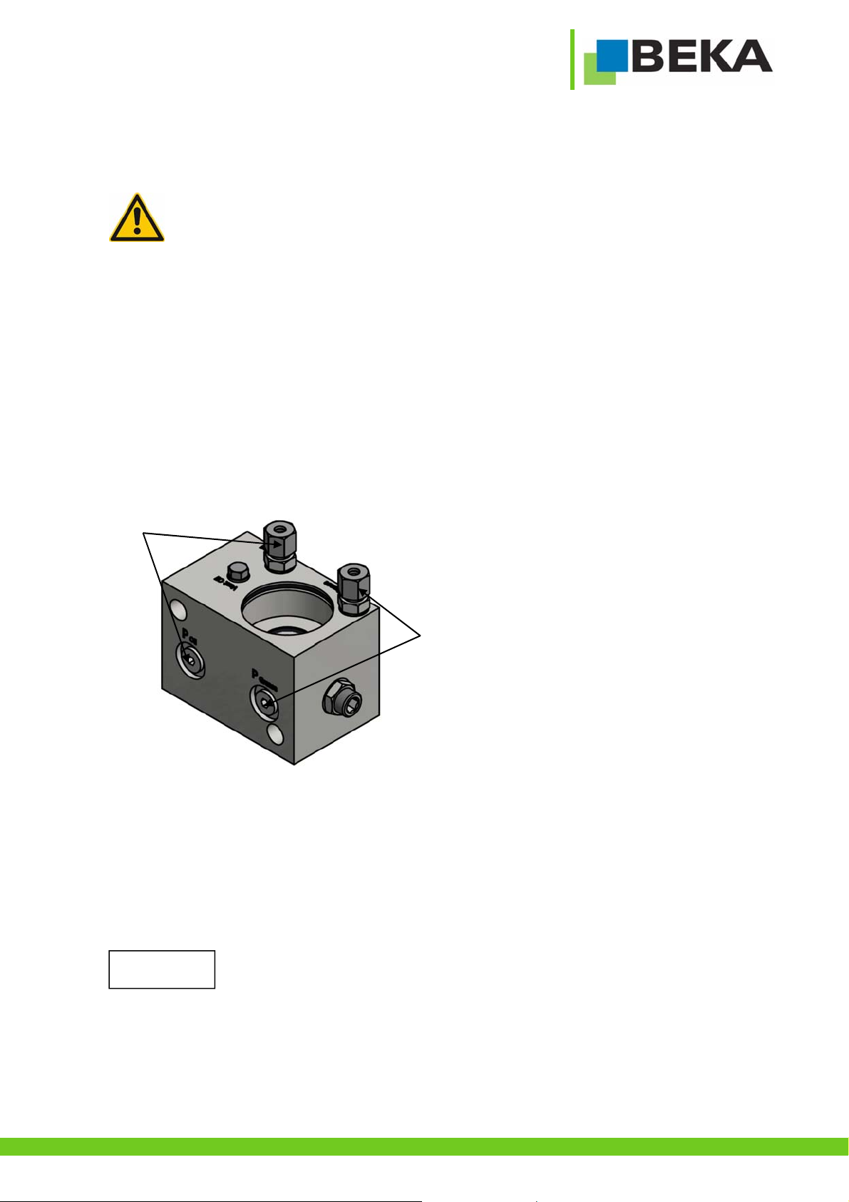
7.1Connection of lines ....................................................................................................................................................................8
7.1.1Lubrication line..................................................................................................................................................................8
7.1.2Hydraulic line .................................................................................................................................................................... 8
8.Start up ...........................................................................................................................................................................................9
8.1Lubricant.................................................................................................................................................................................... 9
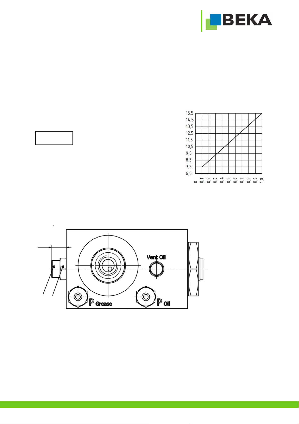
8.2Setting the delivery rate............................................................................................................................................................. 9
8.3Replacement of grease cartridge.............................................................................................................................................10
8.4Ventilation (grease area) .........................................................................................................................................................11
8.5Ventilation (oil area)................................................................................................................................................................. 11
9.Functional description................................................................................................................................................................... 12
9.1General.................................................................................................................................................................................... 12
9.2Function................................................................................................................................................................................... 12
9.3Hydraulic scheme ....................................................................................................................................................................12
9.4Pressure transmission .............................................................................................................................................................13
10.Maintenance .................................................................................................................................................................................14
10.1General maintenance ..............................................................................................................................................................14
10.2Lubricant change .....................................................................................................................................................................14
11.Shutdown......................................................................................................................................................................................14
12.Disposal........................................................................................................................................................................................14
13.Troubleshooting............................................................................................................................................................................15
14.Spare part list and drawing...........................................................................................................................................................15
15.Dimensional drawing AZ300548...................................................................................................................................................16
16.Details of the manufacturer...........................................................................................................................................................17

Page 3 © BEKA 2018 All rights reserved!
...a product of
1. Technical data
General:
Drive type: ...................................................................................................................................................................................hydraulic
min. drive pressure:.........................................................................................................................................................................80 bar
max. drive pressure:......................................................................................................................................................................250 bar
max. relief pressure (back pressure):..............................................................................................................................................20 bar
max. lubrication outlet pressure: ...................................................................................................................................................210 bar
Hydraulic connection: ................................................................................................................................................................S8 – G1/4
Pressure connection:.................................................................................................................................................................S8 – G1/4
Delivery rate: ...............................................................................................................................................from 0,1 up to 1,0 cm³/stroke
Oil purity class: ....................................................................................................................................................... ISO 4406: ≤17/15/12
Sound pressure level:.................................................................................................................................................................<70dB(A)
Delivery rate regulation:
Regulation range:................................................................................................................................................ infinitely to 8 mm length
No. of strokes: .........................................................................................................................1 stroke per pulse at hydraulic connection
Grease cartridges:............................................................................................................................................................cartridge type F
Grease cartridge capacity: ...........................................................................................................................................................500 cm³
Lubricant:........................................................................................... grease up to NLGI class 2 (grease with solid content on demand)
Temperature range:........................................................................................................................................................ 0°C up to +50°C
Installation position:..........................................................................................................................................cartridge vertically upright
The grease lubrication pump is subsequently called a device.
2. Code
2.1 Cartridges
Designation Article number
Cartridge type F with EP-2 grease Lagermeister ........................................................................................................................ 0320089
Cartridge type F with NLGI 2 grease Meißelpaste ...................................................................................................................... 0320090

Page 4 © BEKA 2018 All rights reserved!
...a product of
3. General safety instructions
Everybody who is in charge of the assembly, start-up, maintenance and operation of the device must read these instructions carefully.
Furthermore, this manual must always be available at the site of operation!
Basic instructions for setup, operation and maintenance can be found below.
3.1 Safety instructions
Observe the general safety instructions within this key chapter as well as the special safety instructions in other chapters of this
operating and assembly manual.
Warning of electrical voltage.
Safety instructions, which might cause hazards to persons in case of non-observance, are marked with the general
danger symbol.
This symbol warns of hot surfaces.
Warning of suspended loads.
This heading is used if improper or general non-observance of the operating and assembly manual,
instructions, specified workflow and the like might result in damage.
This term is used to point out particular details.
Instructions and notes directly attached to the device have to be strictly observed and kept in readable condition!
3.2 Qualification and training of staff
The staff in charge of operation, maintenance, inspection and assembly have to be qualified accordingly. Competence,
responsibilities and supervision of staff must be clearly defined by the operator. In case the staff does not have the
necessary knowledge it has to be instructed and trained accordingly. The operator is obliged to ensure that the staff
fully understands the contents of this user information.
Notice!
Caution!

Page 5 © BEKA 2018 All rights reserved!
...a product of
3.3 Hazards in case of non-observance of the safety instructions
Results of non-observance of the safety instructions can be hazards to persons, for the environment and the
device. Non-observance of the safety instructions may result in the loss of any liability claims. The non-observance
could more specifically result in the following hazards (for example):
Failure of important device functions.
Failure of prescribed methods regarding maintenance and repair.
Danger to persons by electrical, mechanical and chemical effects.
Danger to the environment by leakage of hazardous substances.
3.4 Obligations of the operator / user
If movable, rotating, hot or cold parts of the device bear risks, the customer must protect these parts against
contact. This protection must not be removed.
Any leakages of hazardous substances must be drained in a way that no risks for persons or the environment
arise.
Observe all legal provisions.
Hazards due to electricity are to be excluded.
Examination of pipes and hoses regarding safe provision, use, proper assembly and function has to be carried out
according to regionally applicable directives. Inspection intervals may not be exceeded.
Defective pipes or hoses must be replaced immediately and professionally.
Hydraulic hoses and polyamide pipes are subject to natural aging and have to be exchanged in regular intervals
according to the manufacturer’s specifications.
A safety data sheet of the currently used lubricant must be provided at the device.
Observe the universally valid Ordinance on Hazardous Substances in the latest version.
3.5 Safety instructions for maintenance, inspection and assembly
All maintenance, inspection and assembly work may only be carried out by qualified personnel who is sufficiently
informed by thorough reading of the user information.
Any work at the device may generally only be carried out at complete standstill and in pressureless as well as
disconnected condition. Furthermore, appropriate personal protective equipment (goggles among others) is
necessary. The shutdown procedure of the device as described in the manual must be strictly followed.
Secure the device against intentional or unintentional recommissioning during maintenance or repair. All safety and
protection arrangements have to be put back in place again immediately after completion of the work.
Environmentally hazardous media must be disposed of professionally and according to the relevant legal provisions.
Polluted and contaminated surfaces have to be cleaned before maintenance. Please wear protective equipment to
that purpose. See the lubricant manufacturers‘ safety data sheets hereto, respectively the data sheets provided by the
manufacturers of auxiliaries and working materials.
Check the surface temperature of the device as a possible heat transfer bears the risk of burns. Wear heat resistant
protective gloves!
Open flame and fire are strictly forbidden during maintenance, inspection and repair due to fire hazard.
3.6 Unauthorized modification and production of spare parts
Modification, repair and alterations of the device are only accepted after manufacturer feedback. Original spare parts
and authorized accessories from the manufacturer contribute to safety. The use of other parts can result in the loss of
any liabilities for the resulting consequences. BEKA does not assume liability for parts that are retrofit by the operator.

Page 6 © BEKA 2018 All rights reserved!
...a product of
3.7 Inadmissible modes of operation
Operational safety of the device is only guaranteed when it is appropriately applied as indicated in the operating and assembly manual.
Never exceed or fall below the limit values, as stated in the technical data.
3.8 General hazard warning – residual risk
All components are designed according to valid regulations for the construction of technical systems with regard to
operational safety and accident prevention. Nevertheless, their use can lead to hazards for the user or third parties as
well as other technical facilities. Therefore the device may only fulfill its intended purpose in a technically perfect and
faultless condition. This has to happen in adherence to the relevant safety regulations as well as the operating and
assembly manual. Inspect the device and its attachment parts regularly and check them for possible damage or
leakages. Liquids could escape under high pressure from pressurized components which become leaky.

Page 7 © BEKA 2018 All rights reserved!
...a product of
4. Intended use
The device is only approved for the industrial use.
Only operate the device if it is installed in/at another machine and operated together with it.
Only lubricants which comply with the machine manufacturer’s specifications may be conveyed.
The device must only be used according to the technical data (see chapter 1 „Technical data”). The values
may never exceed or fall below the values mentioned in the technical data. Never operate the device without
lubricant.
Unauthorized modifications of the device are not permitted. BEKA is not liable for personal injury or damage of machine resulting
thereof.
The intended use also includes:
paying attention to all chapters and notes in the operating and assembly manual.
carrying out all maintenance work.
observing all relevant instructions for work safety and accident prevention during all life cycles of the device.
having the necessary professional training and authorization of your company to operate the device and to carry out the necessary
work on the device.
Another use or a use beyond this scope is deemed improper.
5. Scope of warranty
Warranties regarding operational safety, reliability and performance will only be granted by the manufacturer if the device is used
according to the regulations and under the following conditions:
Assembly, connection and maintenance are only carried out by authorized and qualified staff.
The device is only used according to the operating and assembly manual.
Never exceed or fall below the limit values as defined in the technical data.
Modifications and repairs at the device may only be done by BEKA.
Guaranty and warranty will expire for any damage of the device caused by improper lubricant (e.g. wear of
piston, piston jamming, blockades, brittled sealings etc.).
BEKA will generally not accept guaranty claims for any damage caused by lubricants, even though those
have been laboratory tested and released by BEKA, as such damage (e.g. by over-stored or incorrectly
stored lubricants, batch fluctuations, etc.) cannot be verified or reconstructed later.
6. Transport and storage
Use suitable lifting devices for transport.
Do not throw the device or expose it to shocks.
Secure the device against toppling down or slipping during transport.
Observe all valid safety and accident prevention regulations for the transport. Wear suitable protective equipment if
necessary. Keep adequate distance to suspended loads. The transport help or the elevating device must have the
adequate carrying capacity.
When storing the device pay attention that the storage area is cool and dry in order to avoid corrosion of the individual parts of the
device.
Caution!
Caution!
Caution!

Page 8 © BEKA 2018 All rights reserved!
...a product of
7. Assembly instructions
Check the device for possible transport damage and for completeness before the assembly. Any installed equipment for transportation
safety has to be removed.
Comply with the following conditions for assembly of the device in order to obtain a properly built together machine of
all parts without compromise of safety or persons’ health:
Assemble the device in balance on the installation location in order to ensure safe operation. Observe the information on the fastening
holes given in the dimensional drawing. When selecting the set-up location, please mind that the device should be protected against
ambient and mechanic influences. Ensure full access, e.g. for filling with lubricant.
Special measures concerning noise prevention or oscillation reduction do not have to be taken.
7.1 Connection of lines
Professional layout!
When using pipes, observe that they are clean, seamless and of precision steel!
Assemble the pipes professionally and free from distortion!
Pay attention to pressure tightness of fittings!
All components must be approved for max. operating pressure (see technical data).
The connections for lubrication (B, fig. 1) and hydraulic lines (A, fig. 1) can be optionally attached to two different positions (on top
or at the back of the housing). The outlet which is not used has to be locked with the plug screw.
7.1.1 Lubrication line
A high-pressure hose with hose connections has to be mounted into the connection at the lubrication outlet (B, Fig.2) for the
lubrication line.
7.1.2 Hydraulic line
Hydraulic connection must be assembled by a qualified specialist!
Compare the existing hydraulic pressure with the stated min. and max. operating pressure!
The hydraulic connection needs to be carried out referring to the instructions of these assembly instructions.
Put a bypass line from the hydraulic system of the carrier unit to the hydraulic connection of the device (A, Fig.1)
This line has to be relieved to drain surplus oil from the hydraulic pressure chamber in the reservoir during the
lubrication supply.
A
B
Fig. 1
Notice!

Page 9 © BEKA 2018 All rights reserved!
...a product of
8. Start up
8.1 Lubricant
Observe the machine manufacturer’s lubricant details! Only use lubricants according to machine manufacturer’s specifications!
Collect leaking lubricant in a suitable reservoir and dispose it professionally!
Observe the safety data sheet of the lubricant manufacturer!
The lubricant viscosity changes with the operating temperature.
8.2 Setting the delivery rate
The delivery rate can be set progressively via the setscrew (D, Fig. 3)
for the delivery rate within a range from 0,1 to 1,0 cm³/stroke. Normally
the delivery rate is preadjusted to 1,0 cm³/stroke. Dimension E
determines the flow rate of the device (see Fig. 2). The set screw can
be set infinitely over a length of 6.5 mm to 15.5 mm.
The delivery rate is 0 at a stroke adjustment of
6.5 mm. This setting results in an increased
pump wear and is to be avoided. The set screw
(D, fig. 3) must not be screwed out of the device
further than the dimension 15.5 mm because it
falls out of the housing and dirt can enter the
device.
Release lock nut (C, Fig. 3)
Set delivery rate via the setscrew (D, Fig. 3)
-Turn clockwise to reduce the delivery rate; turn counter-
clockwise to increase it.
-One turn of the setscrew corresponds to 1 mm and approx.
0,1 cm³/stroke
Retighten lock nut. (C, Fig. 3)
Fig. 3
C
D
E
Stroke setting „E“ in mm
Delivery rate in cm³/stroke
Fig.2
Caution!

Page 10 © BEKA 2018 All rights reserved!
...a product of
8.3 Replacement of grease cartridge
The device is filled with commercially available grease cartridges of type F.
The device can also be operated using Interlube cartridges.
Dimensions:
Type F cartridge Interlube cartridge
Observe utmost cleanness when changing the grease cartridge!
Unscrew grease cartridge counter-clockwise out of the pump housing
(Fig. 5).
Dispose empty grease cartridge properly.
Screw in the new cartridge clockwise into the pump housing.
Air may have entered into the system through the grease cartridge
replacement. The grease area must be bled after each grease cartridge
replacement!
Fi
g
. 4
M20
Ø62
10
M20
Ø62
14
170
245
Fig. 5

Page 11 © BEKA 2018 All rights reserved!
...a product of
8.4 Ventilation (grease area)
Ventilate the complete system after the start-up as well as after a grease cartridge exchange.
Ventilation is done by operating the system in pressureless condition and with open system outlets. Remove the pressure line from
the fitting (G, Fig. 6).
Operate the device until lubricant comes out of the pressure connection without air inclusions!
8.5 Ventilation (oil area)
Ventilate the oil section of the device after each first- or reconnection of the hydraulic connection.
Release ventilation screw (F, Fig. 6) (it is not necessary to turn it out completely).
Fill oil area until oil escapes through the ventilation screw.
Retighten ventilation screw.
F
G
Fig. 6

Page 12 © BEKA 2018 All rights reserved!
...a product of
9. Functional description
9.1 General
The device is designed to deliver multi-purpose grease NLGI grade 2. Thanks to the use of grease cartridges of type F, the lubricant
supply can be replenished quickly and tidily.
The device is equipped with a lubricant out.et to which e. g. a progressive distributor can be connected. The lubricant quantity can be
set progressively, so that the device can be used for all lubricant circuits.
9.2 Function
The device is supplied with hydraulic oil via the hydraulic connection (S. fig. 7). With at each pressurization with hydraulic oil, the
compression spring (R, fig. 7) is compressed. The delivery piston (Q, fig. 7) moves to the left and locks the suction bore (N, fig. 7). The
lubricant (M, fig. 7) from the suction chamber (P, fig. 7) flows through a non-return valve, to the pressure connection (L, fig. 7). The
non-return valve prevents at the back stroke that the lubricant is sucked back into the suction chamber.
The compression spring (R, fig. 7) presses the delivery piston (Q, fig. 7) back into its initial position after the pressure stroke. The
vacuum, which has arisen, sucks the lubricant (M, fig. 7) into the suction chamber (P, fig. 7) for the next pressure stroke. The delivery
volume can be set infinitely over a length from 0.1 cm³ to 1 cm³ via the setscrew (O, fig. 7).
9.3 Hydraulic scheme
Fig. 8
Fi
g
. 7

Page 13 © BEKA 2018 All rights reserved!
...a product of
9.4 Pressure transmission
The delivery pressure is directly related to the hydraulic pressure which actuates the device (see Fig. 8).
Hydraulic inlet pressure in bar
Lubricant outlet pressure in bar
Fig. 8

Page 14 © BEKA 2018 All rights reserved!
...a product of
10. Maintenance
Disconnect the device from power supply before maintenance or repairs.
Only carry out maintenance and repair in complete device standstill and pressureless condition.
Check the surface temperature of the device to avoid the risk of burns by radiant heat. Wear heat-resistant gloves
and safety goggles! Clean soiled or contaminated surfaces before maintenance, wearing protective equipment if
necessary! Secure the device against recommissioning during maintenance and repair work!
10.1 General maintenance
Retighten all fittings 6 weeks after start up!
Check all components for leakages and damage at least every four weeks!
If leakages are not repaired, lubricant might escape under high pressure. Remove possible puddles of lubricant
immediately.
10.2 Lubricant change
Pay attention to utmost cleanness when refilling lubricant!
Check the level regularly and change cartridge as necessary, see chapter start up.
Change the lubricant according to the specifications of the lubricant manufacturer. Environmental influences like increased
temperature or pollution may shorten these intervals!
Please make sure to only use lubricants that are suitable for the device as well as the lubricated machine and that comply with the
requirements of the particular operating conditions.
11. Shutdown
Relieve the device from pressure!
Remove all pipes and hoses from the device and loosen all fastenings for disassembly!
12. Disposal
Observethedisposal instructionsof the lubricant manufacturer when lubricant is changed!Lubricants
or cloths contaminated with lubricant, etc. must be collected in specially marked reservoirs and
disposed of accordingly.
Disposal of the device must be done properly and professionally and according to the national and
international laws and regulations.
Caution!
Notice!

Page 15 © BEKA 2018 All rights reserved!
...a product of
13. Troubleshooting
Malfunction Possible cause Possible remedy
Pump does not deliver
lubricant
No hydraulic oil pressure at hydraulic
connection
Check the pressure at the hydraulic connection
Pressure spring broken Renew pressure spring
Delivery rate adjusted to 0,0 cm³/stroke Adjust delivery rate
Cartridge empty Change cartridge
Sealing to cartridge leaky Renew sealing
Counter pressure in lubrication system
too high (line rest pressure too high)
Check lubrication system
Lubricant quantity too
low or too high
Delivery rate adjusted wrong Adjust delivery rate
14. Spare part list and drawing
You will get a spare part list and drawing on request.

Page 16 © BEKA 2018 All rights reserved!
...a product of
15. Dimensional drawing AZ300548

Page 17 © BEKA 2018 All rights reserved!
...a product of
16. Details of the manufacturer
BEKA
BAIER + KÖPPEL GmbH + Co. KG
Beethovenstraße 14
91257 PEGNITZ / Bayern
Germany
Tel. +49 9241 729-0
FAX +49 9241 729-50
POSTFACH 1320
91253 PEGNITZ / Bayern
Germany
http://www.beka-lube.de
Our range of supply:
Gear pumps
Multi-line oil pumps
Multi-line grease pumps
Single-line central lubrication systems
Dual line central lubrication systems
Oil circulation central lubrication systems
Oil-air and spray lubrication
Wheel flange central lubrication systems
Rolling mill central lubrication systems
Commercial vehicle lubrication
Progressive distributors
Control and monitoring units
Subject to alterations!
We do not accept liability for errors,
technical mistakes and misprints!
Table of contents
Other BEKA Water Pump manuals

BEKA
BEKA HPM-2S Product guide

BEKA
BEKA Stream E 2520 Series Product guide

BEKA
BEKA PICO-troniX1 Product guide

BEKA
BEKA BEKA-MAX OC-1 User manual

BEKA
BEKA EP-1 Product guide

BEKA
BEKA PICO Series Product guide

BEKA
BEKA Stream H Product guide

BEKA
BEKA ZEPTO Product guide

BEKA
BEKA HAMAX System 2 User manual

BEKA
BEKA HAMAX Kompakt M14 Product guide
Popular Water Pump manuals by other brands

Crane
Crane Barnes 3SE3032L Installation and operation manual

FAG
FAG PUMP1600 operating instructions

Wayne
Wayne ESP15 Operating instructions and parts manual

Senci
Senci SCWT-100 operation instruction

STERWINS
STERWINS 1100 WT 24 SM3I-3 Characteristics

EINHELL
EINHELL ROYAL TMP 501/1-S NIRO operating instructions