Beko DRYPOINT M eco control Quick start guide

DRYPOINT®M eco control
DEC 1-30S
DEC 2-40S
DEC 3-60S
DEC 4-80S
DEC 5-115S
DEC 6-135S
DEC 7-165S
DEC 8-250S
DEC 9-330S
Drying system
Installation and operation manual
EN - English
07-068

Installation and operation manual EN
2 DRYPOINT®M eco control
Contents
1. Safety-related information.............................................................................................................................. 4
1.1. Pictograms and symbols.......................................................................................................................... 4
1.1.1. In this documentation........................................................................................................................................................4
1.1.2. On the device.......................................................................................................................................................................4
1.2. Signal words according to ISO 3864 and ANSI Z.535 ................................................................................ 5
1.3. Safety instructions.................................................................................................................................. 5
1.4. Transport and storage ............................................................................................................................. 6
1.5. Intended use........................................................................................................................................... 7
1.6. Warranty and liability for defects ............................................................................................................ 7
2. Product information ....................................................................................................................................... 8
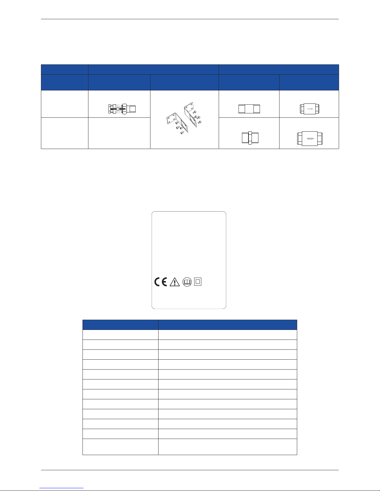
2.1. Scope of delivery .................................................................................................................................... 8
2.2. Type plate............................................................................................................................................... 8
2.2.1. Rating plate for the drying system..................................................................................................................................8
2.2.2. Rating plate for control unit .............................................................................................................................................9
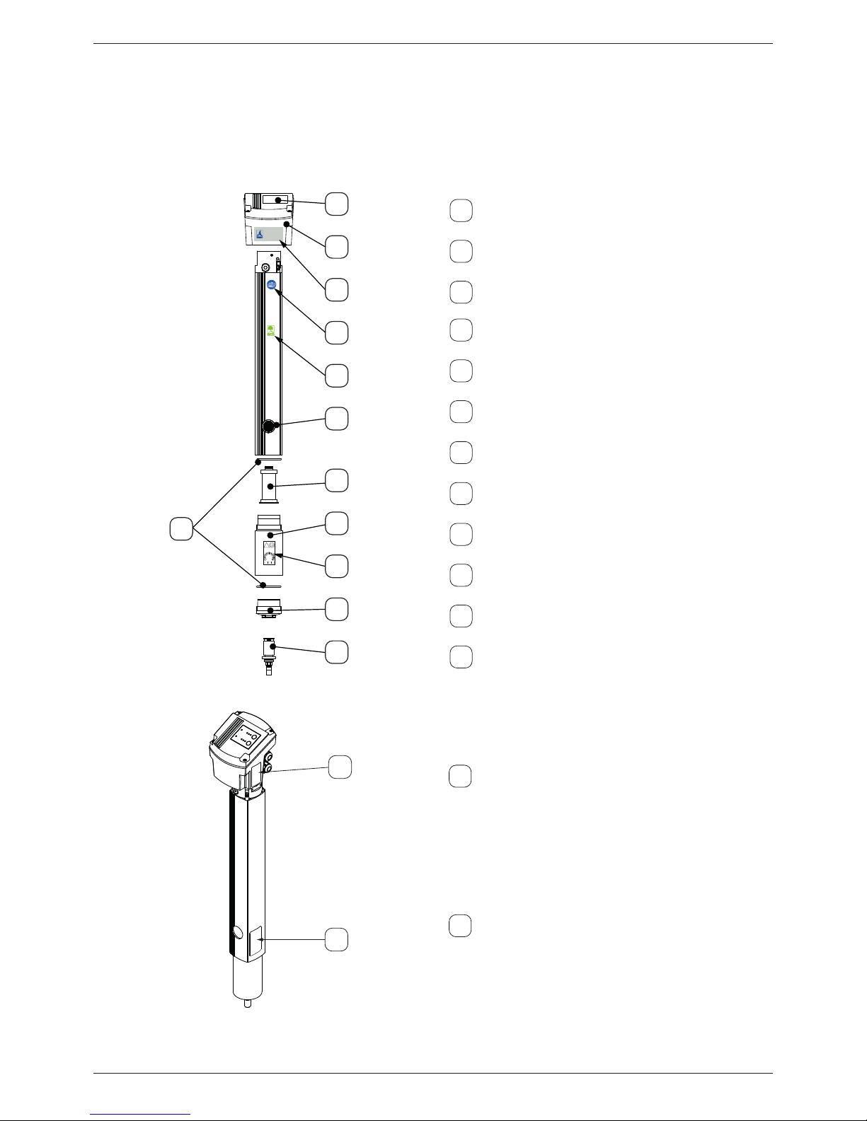
2.3. Product overview and description ......................................................................................................... 10
2.4. Parts and components........................................................................................................................... 11
2.4.1. Principle function methods............................................................................................................................................ 12
2.4.2. Operating mode ............................................................................................................................................................... 13
2.5. Control and display elements ................................................................................................................ 14
2.6. 4 ... 20 mA interface.............................................................................................................................. 15
2.7. Alarm relay........................................................................................................................................... 15
2.8. Dimensions........................................................................................................................................... 16
2.9. Technical data....................................................................................................................................... 17
3. Assembly...................................................................................................................................................... 21
3.1. Prerequisites ........................................................................................................................................ 21
3.2. Assembly steps ..................................................................................................................................... 22
4. Electrical installation .................................................................................................................................... 23
4.1. Warning................................................................................................................................................ 23
4.2. Terminal positions................................................................................................................................. 23
4.3. Opening the control unit....................................................................................................................... 24
4.4. Connection of voltage power cable to power supply board..................................................................... 25
4.5. Connection of 4 ... 20 mA interfaces on the control unit PCB.................................................................. 25
4.6. Connection of equipotential contact on the control unit PCB ................................................................. 25
5. Commissioning ............................................................................................................................................. 25
6. Operation..................................................................................................................................................... 26
6.1. Indicators in operation.......................................................................................................................... 26
6.2. Solenoid valve test function .................................................................................................................. 27
6.3. Acquiring settings (set-up mode) .......................................................................................................... 27
6.3.1. Amend the operating mode........................................................................................................................................... 27
6.3.2. Altering the values........................................................................................................................................................... 27
6.3.3. Service mode..................................................................................................................................................................... 28
7. Maintenance and servicing............................................................................................................................ 28

EN Installation and operation manual
DRYPOINT®M eco control 3
7.1. Maintenance schedule .......................................................................................................................... 28
7.1.1. Function and visual inspections.................................................................................................................................... 28
7.1.2. Filter element maintenance........................................................................................................................................... 29
7.1.3. Exchanging the control unit........................................................................................................................................... 30
7.1.4. Replacing the oat drain-o conduit........................................................................................................................... 34
7.1.5. Wear part exchange......................................................................................................................................................... 35
7.1.6. Measuring the permeation rate.................................................................................................................................... 42
7.1.7. Cleaning.............................................................................................................................................................................. 43
8. Spare parts and accessories........................................................................................................................... 43
9. Remedying malfunctions, errors, faults and troubleshooting ......................................................................... 44
9.1. Behaviour in the event of malfunctions/errors, faults ............................................................................ 44
9.1.1. Failure of the voltage power supply............................................................................................................................. 44
9.1.2. Sensor failure..................................................................................................................................................................... 44
9.1.3. Deviating degree of drying ............................................................................................................................................ 45
9.2. FAQ ...................................................................................................................................................... 46
10. Decommissioning ....................................................................................................................................... 48
11. Dismantling and disposal ............................................................................................................................ 48
12. Declaration of Conformity .......................................................................................................................... 49

Installation and operation manual EN
4 DRYPOINT®M eco control
1. Safety-related information
1.1. Pictograms and symbols
1.1.1. In this documentation
General instructions
Observe installation and operating instructions
General hazard symbol (danger, warning, caution)
General hazard symbol (danger, warning, caution) for mains voltage
and mains voltage energised plant and system parts
1.1.2. On the device
eco label
Symbol for particularly energy-ecient devices
!
20.. 20.. 20..
Maintenance information for nanolter:
Details relating to next required lter exchange
Maintenance information for nanolter:
Never open the housing lid when exchanging the lter
General instructions
General hazard symbol (danger, warning, caution)
General hazard symbol (danger, warning, caution) for mains voltage
and mains voltage energised plant and system parts

EN Installation and operation manual
DRYPOINT®M eco control 5
1.2. Signal words according to ISO 3864 and ANSI Z.535
DANGER! Imminent danger
Consequences of non-compliance: serious or even fatal injury
WARNING! Potential danger
Consequences of non-compliance: possibly serious or even fatal injury
CAUTION Imminent danger
Consequences of non-compliance: injury and/or damage to property
NOTE Additional notes, information, tips
Consequences of non-compliance: Disadvantages during operation and maintenance.
No risk to persons.
1.3. Safety instructions
DANGER! Escaping compressed gas
Risk of serious or even fatal injury from suddenly released compressed gas, condensate or
unsecured system components.
• Before carrying out any assembly, installation or maintenance work, depressurise the system.
These works may only be executed by authorised specialist technical personnel1.
• Use only pressure-resistant installation materials and suitable tools that are in proper working
order.
• Before pressurising the system, check all unit parts and repair them, if necessary. Open valves
slowly to prevent pressure blow outs during operation.
• Always prevent people or objects from being aected by condensate or escaping compressed
gas.
• Prevent vibrations, oscillations and impact from being transferred to system parts.
• Perform a leakage test.
DANGER! Mains voltage
Risk of electric shock with serious or even fatal injuries if contact is made with non-insulated, live
components.
• Observe all applicable regulations with respect to electrical installations (e.g. VDE 0100 / IEC
60364).
• Only execute installation and maintenance works when the system has been deenergised.
• Electrical works may only be executed by authorised specialist technical personnel1.
• Read o the permissible operating voltage on the rating plate and always comply with it.
• Only utilise components for the electrical installation which have a current approval
and are labelled with a CE-Identication Marking.
• A safely accessible circuit breaker (e.g. power plug or switch) must be provided close to the unit
for disconnecting all current and/or power lines for the voltage supply.
WARNING! Operating outside of limits
If the specied limits are undershot and/or exceeded, there is a risk of device malfunction,
potentially resulting in injury and/or damage to property.
• The device must only be operated for the intended purpose and within the permissible limits
specied on the type plate and in the technical data.
• Strictly adhere to the prescribed operating times and maintenance intervals.
• Strictly adhere to the prescribed storage and transport conditions.
1 Specialist technical personnel
Specialist technical personnel are people who, due to their professional qualication and knowledge in the eld of
measuring, control and pneumatic technology, and their knowledge of the applicable statutory regulations, guidelines
and standards are in a position to independently foresee potential dangers in relation to the use of the device and who
are qualied to perform the tasks described in this manual. Special operating conditions (e.g. aggressive media) require
additional knowledge.

Installation and operation manual EN
6 DRYPOINT®M eco control
1.4. Transport and storage
Despite our best eorts regarding packaging etc., the device might be damaged during transport. Please therefore remove
all packaging material immediately after receipt and inspect the product for any possible transport damage. Any damages
must be immediately notied to the transport company and BEKO TECHNOLOGIES GMBH or one of their agents.
CAUTION Damage caused during transport or storage
Incorrect transport or storage, or the use of unsuitable lifting equipment, might cause damage to
the device.
• The device must only be transported and stored by authorised and suitably trained technical
personnel.
• If you detect any damage, do not start the device.
• Always comply with the permissible storage and transport temperatures (refer to technical
data).
• Never expose the device to continuous, direct sunlight or heat radiation.
The device must be stored in the original
packaging. Seal the packaging and store it in a
dry and frost-free room. Ensure that the ambient
conditions do not fall below or exceed the limits
specied on the type plate.
Always take suitable measures to protect the
device against the elements even in a packaged
condition.
While in storage, secure the device so that it
cannot topple over or fall, and protect it against
vibration.
NOTE Recycling packaging material
• The packaging material is recyclable. Dispose of the packaging material according to the
applicable statutory regulations.

EN Installation and operation manual
DRYPOINT®M eco control 7
1.5. Intended use
The DRYPOINT® M eco control drying system with integrated nanolter and pressure dew point control is designed for the
removal of aerosols and particles from compressed air and subsequent targeted drying of the air according to the individual
settings by the user.
Operate the DRYPOINT® M eco control only for the intended purpose and within the limit range specied in the technical
data. Do not operate the unit with any media (uids, gas/vapour mixtures) other than those listed above. Any other use
of this system, which exceeds the intended use, is hereby deemed to be improper and can cause a hazard for the safety of
people and the environment.
• Operating the unit may only be executed within the permissible operating parameter limits (refer to technical data).
• Operating pressure will be required for the proper functional operation.
• The device is not suitable for operation in explosion hazard areas as well as in areas with aggressive atmospheres.
• Do not operate the device with corrosive gases.
• Strictly observe the prescribed storage and transport conditions.
• The device is not suitable for use in conjunction with CO²systems.
The operating company must establish measures for the monitoring of the compressed air quality when using industrial
processes with higher quality requirements (e.g. food industry, medical technology, laboratory equipment, special processes,
etc.). These inuence the safety for subsequent processes and can prevent injuries to people and damage to plants and
systems. It is the duty of the owner and/or operator to always comply with the stated conditions during the entire operating
time.
1.6. Warranty and liability for defects
All liability claims will be deemed to be invalid when the DRYPOINT-M® eco control is not utilised in accordance with its
intended use or is operated outside the specifications stated in the technical data, this particularly includes:
• Technically incorrect installation, incorrect commissioning, incorrect maintenance or incorrect operation
• Operation with defective components
• Non-compliance with the instructions in this manual, in particular the safety instructions
• Execution of constructive interventions or modications on the device
• Non-compliance with the prescribed maintenance intervals
• Use of third-party spare parts that have not been approved by the manufacturer for repair and maintenance works

Installation and operation manual EN
8 DRYPOINT®M eco control
2. Product information
2.1. Scope of delivery
The following table indicates the scope of delivery for the DRYPOINT®M eco control.
Inlet side Outlet side
Model Ball valve Wall bracket Long nipple/double
nipple
Non-return valve
DEC 1 ... DEC 6
G 1/2 G 1/2 G 1/2
DEC 7 ... DEC 9 -
G 1 G 1
2.2. Type plate
The drying system is equipped with two rating plates: One rating plate for the entire system and one rating plate for the
control unit.
2.2.1. Rating plate for the drying system
DRYPOINT®M eco control
BEKO TECHNOLOGIES
Made in Germany
www.beko-technologies.com
Type: DEC6-135S
Material-no.: 4039476
Serial-no.: 13434090
Lot: 201621
Element: 06N-V02
Element mat.-no.: 4010849
Work. temp. TS:
+2 ... 50 °C / +35 ... 122 °F
Max. work. pr. PS: 4 ... 10 bar / 58 ... 145 psi
Connection: pipe G
1/2
Power supply: 95 ... 240 VAC ± 10 %
50-60 Hz, max. 20 VA(W)
100 ... 125 VDC ± 10 %
Protection-Class: -
PED2014/68/EU/Category - Fluidgroup 2
DRYPOINT
Designation Description
Model: Model designation
Material No.: Material number
Serial No.: Serial number
Batch: Date of manufacture
Element: Designation for integrated lter element
Element mat.-no.: Material number for integrated lter element
Work. temp. TS: Permissible minimum/maximum operating temperature
Maximum. working pr. PS: Permissible minimum/maximum operating pressure
Connection: Thread information pipe connection
Power supply: Data for voltage supply
Protection-Class: IP protection class
PED2014/68/EU/Category Permissible uid group according to European Pressure
Equipment Directive

EN Installation and operation manual
DRYPOINT®M eco control 9
2.2.2. Rating plate for control unit
DEC Control Unit
BEKO TECHNOLOGIES
Made in Germany
www.beko-technologies.com
Type: DEC-CU135S
Material-no.: 4039455
Serial-no.: 13434090
Lot: 201621
Work. temp. TS:
+2 ... 50 °C / +35 ... 122 °F
Max. work. pr. PS:
4 ... 10 bar / 58 ... 145 psi
Power supply:
95 ... 240 VAC ± 10 %, 50-60 Hz
100 ... 125 VDC ± 10 % / max. 20 VA(W)
Protection-Class: IP 54
PED2014/68/EU/
Cat. - /Fluidgroup 2
DRYPOINT
Designation Description
Model: Model designation
Material No.: Material number
Serial No.: Serial number
Batch: Date of manufacture
Work. temp. TS: Permissible minimum/maximum operating
temperature
Maximum. working pr. PS: Permissible minimum/maximum operating pressure
Power supply: Data for voltage supply
Protection-Class: IP protection class
PED2014/68/EU/Category Permissible uid group according to European
Pressure Equipment Directive
NOTE Handling of type plate
Never damage, remove or make the type plate illegible.
For more information regarding the symbols printed on the type plate, see “Pictograms and symbols”
on Page 4.

Installation and operation manual EN
10 DRYPOINT®M eco control
2.3. Product overview and description
The DRYPOINT® M eco control is a drying system that guarantees a constant degree of drying even under uctuating
operating conditions. The sensor system integrated into the control unit (2) reacts to uctuating operating pressure, inlet
pressure dew point as well as dierential requirements for compressed air quantities. The display and control elements are
integrated into the control panel (1). The operating modes as well as specied degree of drying are displayed here. A change
of the operating mode or the degree of drying is always possible during running operation.
1
2
3
4
8
5
7
9
6
11
12
10
!
20.. 20.. 20..
Year
Month
NEXTELEMENT
CHANGE
DRYPOINT®M
eco control
1
User interface
2
Control unit/housing head
3
Label: DRYPOINT®M eco control
4
Label: BEKO quality
5
Labels: eco label
6
Purge air outlet
7
Nanolter element
8
O-rings (housing)
9
Housing extension
10
Label: Next element change
11
Housing base
12
Float drain-o conduit
13
14
13
Rating plate for the control unit
14
Rating plate for the drying system

EN Installation and operation manual
DRYPOINT®M eco control 11
2.4. Parts and components
20
21
1
2
3
4
7
5
6
9
8
10
11
12
13
14
24
15
16
17
18
19
5a
27
26
29
25
32
28
30
31
23
22
1
Hood
2
Keyboard foil
3
Mushroom head bolt M3 x 20
4
Cord packing
5
Display printed circuit board with
plug connection
5a
Plug connection sensor
6
Countersunk head screw M3 x 8
7
Plastic washer
8
Screw M5 x 45
9
Washer 5.3
10 Knurled nut anchor system
11
Coil with cable150 mm
12
Screw M3 x 40
13
Retaining plate
14
Anchor system
15
Pilot valve seat
16
Seal pilot valve seat
17
Valve piston with seal
18
Pressure spring switch-over valve
19
Sensor with cable and plug connection
20
O-ring 8 x 1.5
21
Switch-over valve seat
22
Seal switch-over valve seat
23
Housing
24
Control board
25
Cable gland M16 x 1.5
26
Seal
27
Counter nut M16 x 1
28
Pressure compensation plug
29
Sleeve
30
Counter nut M12 x 1.5
31
O-ring 6 x 2
32
Power cable with plug

Installation and operation manual EN
12 DRYPOINT®M eco control
2.4.1. Principle function methods
1
2
4
3
6
7
9
8
11
10
12
5
Moist compressed air (2) enters the unit through the housing
head (1) and ows downwards through the core pipe of the
membrane element (5) into the housing (4). It then passes
through the nanolter (6) installed at the bottom outlet of
the core tube where all residual aerosols and particles are
removed from the compressed air. Separated condensate
ows out of the base and is routed through the oat drain-o
conduit (7).
The ow direction is reversed in the nanolter element area
and the damp compressed air ows through the membranes
of the internal membrane element.
A part of the compressed air ow
(9) is diverted downstream of the membrane element and
passed by the sensor continuously in the purge air control.
The sensor measuring results will be evaluated in the purge
air control and the purge air feed to the membrane dryer will
be opened as required. As a result, the purge air decreases to
atmospheric pressure and is considerably dryer as the damp
contained in the compressed air is distributed to a multiple of
the original volume.
The very dry purge air (10) is fed via the purge air duct in
the head and the purge air nozzle (3) on the external side of
the diaphragm (11) and evenly distributed by the arranged
position of the diaphragms. This means that two air ows
move through the membrane element in an opposite
direction with dierential damp content(5):
Damp compressed air on the inside and dry purge air on the
outside.
Due to the damp dierence, water diuses from the
compressed air into the purge air. The damp purge air (12) is
then released to the ambient air. The compressed air (8) exits
as dry from the membrane dryer.

EN Installation and operation manual
DRYPOINT®M eco control 13
The control software decides in dened cycles on the basis of the measurement results whether, and for how long, the
complete purge air volume must be supplied in order to achieve and stabilise the required degree of drying. This process
will be implemented via a targeted cycling of a solenoid valve. The duration for both subsequent described process steps
therefore varies in every cycle to retain the degree of drying within the specied tolerance range.
Function: Measuring gas ows
A very small partial ow of the dried compressed air
(measuring gas) ows continuously through the internal
duct guide past a temperature and damp sensor (S) to the
measuring gas jet (1). This sensor continuously species the
degree of drying for the compressed air in the measuring gas
and noties the result to the control system.
Function: Purge air ows
The control system continuously compares the measured
degree of drying of the measuring gas with the individual
specied set point value on the DRYPOINT®M eco control.
The valve unit will be actuated with deviations: The solenoid
core (2) and piston (3) close the valve seat so that the
compressed air ows through the purge air nozzle (4)
to the membrane dryer. The drying process commences
immediately.
2.4.2. Operating mode
Constant mode (-10 °C; factory-set as default) - Setting for a constant outlet pressure dew point:
The DRYPOINT®M eco control constantly retains the pressure dew point at the outlet between +10 and –26 °C in this
operating mode. If the set pressure dew point is <5K (kelvin) below the compressed-air temperature, then the set point
pressure dew point is reduced by one step (maximum. -26 °C). As soon as the minimum dierence of 5K is retained, then the
system returns to normal mode.
Dynamic mode - constant dierence between compressed air temperature and outlet pressure dew point:
In this operating mode, the pressure dew point is reduced relative to the compressed air temperature by a specied
dierence between 10 and 55 K. If the compressed air temperature alters, then the pressure dew point will automatically
follow suit. For programme-technical reasons, an increase in the compressed air temperature is limited to 2 °C/h in order to
reduce short-term alterations in the ambient conditions at the installation and/or assembly location.
1
3
2
4

Installation and operation manual EN
14 DRYPOINT®M eco control
2.5. Control and display elements
The operation of the DRYPOINT®M eco control is executed via the user interface on the top of the housing. The current
operating status will be represented by LED indicators.
Test
Power
+10
10
+5
20
0
30
Value
35 45 55
°C
°C
-5 -15 -26
Pressure
Dew
Point
∆
∆
...
...
4
5
1
3
2
1
Power LED (green)
Indicator for the operating mode and voltage
power supply
2
Warning LED (red)
Indicator for alarms, errors and malfunctions in
operation
3
Value LED (green)
Indicator for the set point values
4
>>Test<< button
Setting the operating mode or for testing the
solenoid valve function
5
>>Value<< button
Setting the degree of drying or activating the
service mode
4
+
5
Press and hold the >>Test<< + >>Value<< buttons
Unlock software →change settings
The pressure points on the >>Test<< and >>Value<< buttons are designed in such a way that inadvertent touching cannot
trigger operating functions. The software is programmed in such a way that a button must be pressed for a longer time
(approx. 0.2 second) to acquire a desired operating function.
If an operation function is initiated with a continuous pressing of the button(s), then the device will indicate the possible
commencement of the operation: All green value LEDs (3) ash. A time span of 10 seconds is then open for the action after
releasing the button(s). Every actuation of a button during this time span will result in the time span being available again
for the complete duration.
Once the action has been completed and no button has been pressed for 10 seconds, then the conrmation for nalising
the action will be executed via the control . All green value LEDs (3) ash.
The system then transfers into normal mode and will be controlled on the basis of the prescribed settings.
NOTE Additional information
For more information regarding the display and the test function of the solenoid valve, see “Operation” on
Page 26.

EN Installation and operation manual
DRYPOINT®M eco control 15
2.6. 4 ... 20 mA interface
The drying system is equipped with a 4 ... 20 mA interface via which the currently measured pressure dew point can be
issued (irrespective of operating mode).
4 mA ≙-48 °C
20 mA ≙+25 °C
Output value in case of error 24 mA
Increments: 0.5 °C
2.7. Alarm relay
The drying system is equipped with an alarm relay via which an error signal can be issued. There will not be a dierentiation
here between various types of errors.
Error list:
• Sensor errors (refer to device errors)
• Solenoid valve errors (refer to device errors)
• Exceeding the permissible deviation for degree of drying (Refer to 9.1.3)
• Failure of the voltage power supply (Refer to 9.1.1)

Installation and operation manual EN
16 DRYPOINT®M eco control
2.8. Dimensions
A
110
116
110
C
F
E
D
D1
B1
28
G
G
H
B1
116
C
G
G
DEC3 - DEC6
110
116
C
DEC1 - DEC2
B1
G
G
B1
116
C
G
G
DEC7 - DEC9
B
110
B
110
B
Dimensions DEC 1-30S DEC 2-40S DEC 3-60S DEC 4-80S DEC 5-115S DEC 6-135S DEC 7-165S DEC 8-250S DEC 9-330S
A (mm) 625 685 695 745 815 885 889 1029 1179
B (mm) 52 52 72 72 72 72 104 104 104
B1 (mm) approx. 195 approx. 195 approx. 215 approx. 215 approx. 215 approx. 215 approx. 210 approx. 210 approx. 210
C (mm) 133 133 133 133 133 133 141 141 141
D/D1 (ø mm) 60/60 60/60 80/80 80/80 80/80 80/80 120/120 120/120 120/120
E (mm) 65 65 63 63 63 63 78 78 78
F (mm) 128 128 126 126 126 126 141 141 141
G (mm) 1/2"1/2"1/2"1/2"1/2"1/2"1"1"1"

EN Installation and operation manual
DRYPOINT®M eco control 17
2.9. Technical data
Technical data
DEC 1-30S DEC 2-40S DEC 3-60S DEC 4-80S
DEC 5-115S DEC 6-135S DEC 7-165S DEC 8-250S DEC 9-330S
Size of DRYPOINT®M plus 10-41 10-47 20-48 20-53 20-60 20-67 40-61 40-75 40-90
Min./max. Operating overpres-
sure 4 ... 10 bar
Excess pressure protection
housing Pressure compensation plug
Min./max.
storage/transport temperature +2 ... +50 °C,
Min./max. Ambient temperature +2 ... +50 °C,
Min./max. media temperature +2 ... +50 °C,
Medium Fluid group 2: Compressed air/nitrogen
Medium and quality at diaphragm
dryer inlet Only neutral medium in accordance with PED 2014/68/EU with Class [3: - :3] ISO 8573-1
Noise level << 45 dB (A), no expansion pop
Installation position Vertical
Weight [kg] 3.4 3.6 4.9 5.2 5.5 5.8 10.9 12.0 13.1
Materials Media-contacting parts as corrosion-proof
Materials conforming to RoHS and REACH regulations
Plastic components conforming to UL regulations
Integrated nanolter 0.01 µm / 0.005 mg/m³
Pressure loss 0.1 - 0.3 bar, depending on compressed air volume flow
PDP outlet settings +10 / +7 / +5 / +3 / 0 / -5 / -10 / -15 / -20 / -26 °C
PDP dierence settings 10 / 15 / 20 / 25 / 30 / 35 / 40 / 45 / 50 / 55 K (Kelvin)
Electrical data
Operating voltage 95 ... 240 VAC ± 10% (50 ... 60 Hz) / 100 ... 125 VDC ± 10%
or 24 ... 48 VAC ± 10% (50 ... 60 Hz) / 18 ... 72 VDC ± 10%
Power consumption maximum 20 VA (W) with permanently closed solenoid valve
Recommended wire cross-section min. 0.5 mm²
Recommended connection cable 2-wired, diameter 5 ... 10 mm
Protection class IP 54
Min./max. contact spring load
(potential-free contact) max. 12 VAC / 1 A or 24 VDC / 1 A; min. 5 VDC / 10 mA
Signal output 4…20 mA (PDP outlet)
Interfaces 2 x cable connection M16, cable diameter 5 ... 10 mm

Installation and operation manual EN
18 DRYPOINT®M eco control
PDP inlet Volume ow inlet in ll/minute at 10 bar
+35 °C, +20 °C, +5 °C, DEC
1-30S
DEC
2-40S
DEC
3-60S
DEC
4-80S
DEC
5-115S
DEC
6-135S
DEC
7-165S
DEC
8-250S
DEC
9-330S
+10°C, 628 837 1256 1674 2318 2721 3220 4911 6521
+5°C, -5°C, 499 660 990 1320 1835 2157 2576 3832 5120
+10°C, 0°C, -10°C, 393 523 797 1055 1465 1723 2061 3059 4089
+5°C, -5°C, -15°C, 335 448 671 895 1256 1473 1755 2657 3526
0°C, -10°C, 293 390 586 781 1103 1296 1562 2383 3156
-5°C, -20°C, 261 348 522 696 990 1167 1401 2141 2850
-10°C, -15°C, 240 319 478 638 910 1071 1296 1980 2624
-15°C, -20°C, -26°C, 219 293 440 586 837 982 1199 1819 2415
-20°C, -26°C, 204 272 407 544 779 918 1111 1691 2238
-26°C, 190 253 380 507 728 853 1030 1570 2093
PDP outlet 41 55 82 110 158 185 226 343 452
10 bar Purge air in l/minute at 10 bar *
* the intrinsic permeability is approx. <5% relating to the purge air volume.
PDP inlet Volume ow inlet in ll/minute at 9 bar
+35 °C, +20 °C, +5 °C, DEC
1-30S
DEC
2-40S
DEC
3-60S
DEC
4-80S
DEC
5-115S
DEC
6-135S
DEC
7-165S
DEC
8-250S
DEC
9-330S
+10°C, 546 728 1092 1456 2016 2366 2800 4270 5670
+5°C, -5°C, 434 574 861 1148 1596 1876 2240 3332 4452
+10°C, 0°C, -10°C, 342 455 693 917 1274 1498 1792 2660 3556
+5°C, -5°C, -15°C, 291 389 584 778 1092 1281 1526 2310 3066
0°C, -10°C, 255 339 510 679 959 1127 1358 2072 2744
-5°C, -20°C, 227 302 454 605 861 1015 1218 1862 2478
-10°C, -15°C, 209 277 416 554 791 931 1127 1722 2282
-15°C, -20°C, -26°C, 190 255 382 510 728 854 1043 1582 2100
-20°C, -26°C, 178 237 354 473 678 798 966 1470 1946
-26°C, 165 220 330 441 633 742 896 1365 1820
PDP outlet 38 50 75 100 144 169 206 313 413
9 bar Purge air in l/minute at 9 bar *
* the intrinsic permeability is approx. <5% relating to the purge air volume.
PDP inlet Volume ow inlet in ll/minute at 8 bar
+35 °C, +20 °C, +5 °C, DEC
1-30S
DEC
2-40S
DEC
3-60S
DEC
4-80S
DEC
5-115S
DEC
6-135S
DEC
7-165S
DEC
8-250S
DEC
9-330S
+10°C, 464 619 928 1238 1714 2011 2380 3630 4820
+5°C, -5°C, 369 488 732 976 1357 1595 1904 2832 3784
+10°C, 0°C, -10°C, 290 387 589 779 1083 1273 1523 2261 3023
+5°C, -5°C, -15°C, 248 331 496 662 928 1089 1297 1964 2606
0°C, -10°C, 217 288 433 577 815 958 1154 1761 2332
-5°C, -20°C, 193 257 386 514 732 863 1035 1583 2106
-10°C, -15°C, 177 236 353 471 672 791 958 1464 1940
-15°C, -20°C, -26°C, 162 217 325 433 619 726 887 1345 1785
-20°C, -26°C, 151 201 301 402 576 678 821 1250 1654
-26°C, 140 187 281 375 538 631 762 1160 1547
PDP outlet 34 45 67 90 129 151 185 280 370
8 bar Purge air in l/minute at 8 bar *
* the intrinsic permeability is approx. <5% relating to the purge air volume.

EN Installation and operation manual
DRYPOINT®M eco control 19
PDP inlet Volume ow inlet in ll/min at 7bar
+35 °C, +20 °C, +5 °C, DEC
1-30S
DEC
2-40S
DEC
3-60S
DEC
4-80S
DEC
5-115S
DEC
6-135S
DEC
7-165S
DEC
8-250S
DEC
9-330S
+10°C, 390 520 780 1040 1440 1690 2000 3050 4050
+5°C, -5°C, 310 410 615 820 1140 1340 1600 2380 3180
+10°C, 0°C, -10°C, 244 325 495 655 910 1070 1280 1900 2540
+5°C, -5°C, -15°C, 208 278 417 556 780 915 1090 1650 2190
0°C, -10°C, 182 242 364 485 685 805 970 1480 1960
-5°C, -20°C, 162 216 324 432 615 725 870 1330 1770
-10°C, -15°C, 149 198 297 396 565 665 805 1230 1630
-15°C, -20°C, -26°C, 136 182 273 364 520 610 745 1130 1500
-20°C, -26°C, 127 169 253 338 484 570 690 1050 1390
-26°C, 118 157 236 315 452 530 640 975 1300
PDP outlet 30 40 60 80 115 135 165 250 330
7 bar Purge air in l/minute at 7 bar *
* the intrinsic permeability is approx. <5% relating to the purge air volume.
PDP inlet Volume ow inlet in ll/minute at 6 bar
+35 °C, +20 °C, +5 °C, DEC
1-30S
DEC
2-40S
DEC
3-60S
DEC
4-80S
DEC
5-115S
DEC
6-135S
DEC
7-165S
DEC
8-250S
DEC
9-330S
+10°C, 300 400 601 801 1109 1301 1540 2349 3119
+5°C, -5°C, 239 316 474 631 878 1032 1232 1833 2449
+10°C, 0°C, -10°C, 188 250 381 504 701 824 986 1463 1956
+5°C, -5°C, -15°C, 160 214 321 428 601 705 839 1271 1686
0°C, -10°C, 140 186 280 373 527 620 747 1140 1509
-5°C, -20°C, 125 166 249 333 474 558 670 1024 1363
-10°C, -15°C, 115 152 229 305 435 512 620 947 1255
-15°C, -20°C, -26°C, 105 140 210 280 400 470 574 870 1155
-20°C, -26°C, 98 130 195 260 373 439 531 809 1070
-26°C, 91 121 182 243 348 408 493 751 1001
PDP outlet 26 35 52 70 100 117 144 218 287
6 bar Purge air in l/minute at 6 bar *
* the intrinsic permeability is approx. <5% relating to the purge air volume.
PDP inlet Volume ow inlet in ll/minute at 5 bar
+35 °C, +20 °C, +5 °C, DEC
1-30S
DEC
2-40S
DEC
3-60S
DEC
4-80S
DEC
5-115S
DEC
6-135S
DEC
7-165S
DEC
8-250S
DEC
9-330S
+10°C, 218 291 437 582 806 946 1120 1708 2268
+5°C, -5°C, 174 230 344 459 638 750 896 1333 1781
+10°C, 0°C, -10°C, 137 182 277 367 510 599 717 1064 1422
+5°C, -5°C, -15°C, 116 156 234 311 437 512 610 924 1226
0°C, -10°C, 102 136 204 272 384 451 543 829 1098
-5°C, -20°C, 91 121 181 242 344 406 487 745 991
-10°C, -15°C, 83 111 166 222 316 372 451 689 913
-15°C, -20°C, -26°C, 76 102 153 204 291 342 417 633 840
-20°C, -26°C, 71 95 142 189 271 319 386 588 778
-26°C, 66 88 132 176 253 297 358 546 728
PDP outlet 23 30 45 60 86 101 124 188 248
5 bar Purge air in l/minute at 5 bar *
* the intrinsic permeability is approx. <5% relating to the purge air volume.

Installation and operation manual EN
20 DRYPOINT®M eco control
PDP inlet Volume ow inlet in ll/minute at 4 bar
+35 °C, +20 °C, +5 °C, DEC
1-30S
DEC
2-40S
DEC
3-60S
DEC
4-80S
DEC
5-115S
DEC
6-135S
DEC
7-165S
DEC
8-250S
DEC
9-330S
+10°C, 152 203 304 406 562 659 780 1190 1580
+5°C, -5°C, 121 160 240 320 445 523 624 928 1240
+10°C, 0°C, -10°C, 95 127 193 255 355 417 499 741 991
+5°C, -5°C, -15°C, 81 108 163 217 304 357 425 644 854
0°C, -10°C, 71 94 142 189 267 314 378 577 764
-5°C, -20°C, 63 84 126 168 240 283 339 519 690
-10°C, -15°C, 58 77 116 154 220 259 314 480 636
-15°C, -20°C, -26°C, 53 71 106 142 203 238 291 441 585
-20°C, -26°C, 50 66 99 132 189 222 269 410 542
-26°C, 46 61 92 123 176 207 250 380 507
PDP outlet 19 25 38 50 72 85 104 158 208
4 bar Purge air in l/minute at 4 bar *
* the intrinsic permeability is approx. <5% relating to the purge air volume.
Product selection:
Example for selection drying system for:
• Volume ow utilisation air: 180 l/min
• Operating pressure: 4 bar
• PDP reduction: +5 °C to -20 °C
Search in table for performance data 4 bar
Column PDP inlet “+5 °C“ up to the row “-20 °C“ (PDP outlet)
Search for a value in this row which is larger than the utilisation air ow
Column DEC 5-115S fulls this requirement with nominal value 240 l/minute
Purge air consumption DEC 5-115S: 72 l/minute must be deducted from the inlet volume ow
Max. utilisation volume ow: 168 l/minute device too small select larger device DEC 6-135S
Table of contents
Other Beko Dryer manuals

Beko
Beko DS7431PX0 User manual

Beko
Beko DH 9532 GA0 User manual

Beko
Beko B3T67249WBPB User manual

Beko
Beko DS 8133 G User manual

Beko
Beko DCU 9330 User manual

Beko
Beko TR520 User manual

Beko
Beko DS 7333 PA0 User manual

Beko
Beko DRYPOINT M PLUS User guide

Beko
Beko BDC710W User manual

Beko
Beko DRVS 83 W User manual

Beko
Beko DA 8111 PA User manual

Beko
Beko DRYPOINT M PLUS DM 40-61 C-N User guide

Beko
Beko BDP710W User manual

Beko
Beko DS 7433 GA0W User manual

Beko
Beko DE 8333 PA0 User manual

Beko
Beko DTGCT 7000 W User manual

Beko
Beko DH 9519 GU User manual

Beko
Beko DC 7110 User manual

Beko
Beko TR215 User manual

Beko
Beko DS 7331 PA0 User manual