Beko DRYPOINT M intelligence User manual

DRYPOINT®M intelligence
MDi 12 | -LV
MDi 17 | -LV
MDi 25 | -LV
MDi 35 | -LV
MDi 45 | -LV
MDi 55 | -LV
MDi 65 | -LV
MDi 100 | -LV
MDi 130 | -LV
Drying system
Installation and operation instructions
US-EN - English US
07-079

Installation and operation instructions US-EN
2 DRYPOINT®M intelligence
Contents
1. Safety information.......................................................................................................................................... 4
1.1. Pictograms and symbols.......................................................................................................................... 4
1.1.1. In this documentation........................................................................................................................................................4
1.1.2. On the device.......................................................................................................................................................................4
1.2. Signal words according to ISO 3864 and ANSI Z.535 ................................................................................ 5
1.3. Safety instructions.................................................................................................................................. 5
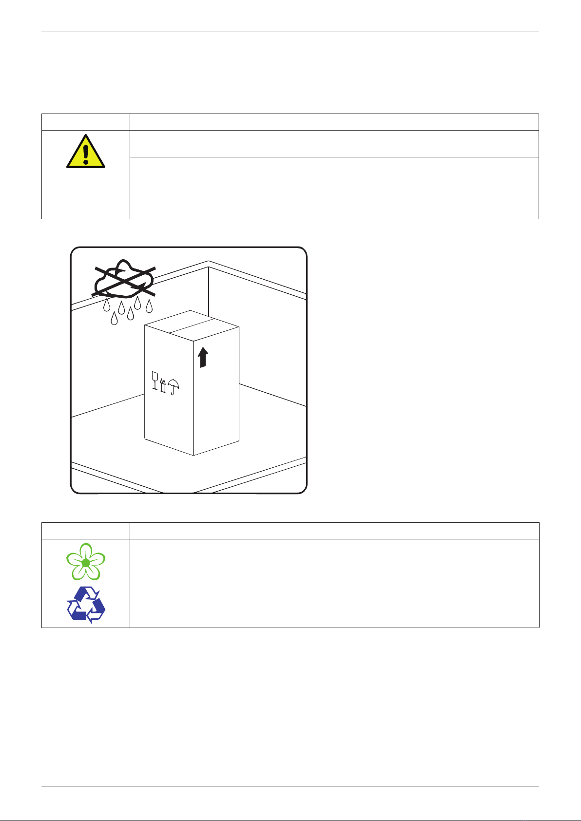
1.4. Transport and storage ............................................................................................................................. 6
1.5. Intended use........................................................................................................................................... 7
1.6. Warranty and liability ............................................................................................................................. 7
2. Product information ....................................................................................................................................... 8
2.1. Scope of delivery .................................................................................................................................... 8
2.2. Name plate ............................................................................................................................................. 8
2.2.1. Name plate of drying system............................................................................................................................................8
2.2.2. Type plate of control unit ..................................................................................................................................................9
2.3. Product overview and description ......................................................................................................... 10
2.3.1. Operating principle.......................................................................................................................................................... 11
2.3.2. Operating mode ............................................................................................................................................................... 12
2.4. Control and display elements ................................................................................................................ 13
2.5. 4 ... 20 mA interface.............................................................................................................................. 14
2.6. Alarm relay........................................................................................................................................... 14
2.7. Dimensions........................................................................................................................................... 15
2.8. Technical data....................................................................................................................................... 16
3. Installation................................................................................................................................................... 20
3.1. Preconditions ....................................................................................................................................... 20
3.2. Installation ........................................................................................................................................... 21
4. Electrical installation .................................................................................................................................... 22
4.1. Warning................................................................................................................................................ 22
4.2. Terminals.............................................................................................................................................. 22
4.3. Opening the control unit....................................................................................................................... 23
4.4. Connection of power cable to power supply board................................................................................. 24
4.5. Connection of 4 ... 20 mA interface to control unit PCB.......................................................................... 24
4.6. Connection of oating contact to control unit PCB ................................................................................ 24
5. Commissioning ............................................................................................................................................. 24
6. Operation..................................................................................................................................................... 25
6.1. LED signals during operation................................................................................................................. 25
6.2. Solenoid valve test function .................................................................................................................. 26
6.3. Adjust settings (setup mode) ................................................................................................................ 26
6.3.1. Change operating mode ................................................................................................................................................. 26
6.3.2. Changing settings ............................................................................................................................................................ 26
6.3.3. Service mode..................................................................................................................................................................... 27

US-EN Installation and operation instructions
DRYPOINT®M intelligence 3
7. Maintenance and servicing............................................................................................................................ 27
7.1. Maintenance schedule .......................................................................................................................... 27
7.1.1. Function testing and visual inspection ....................................................................................................................... 27
7.1.2. Changing lter element.................................................................................................................................................. 28
7.1.3. Replacing control unit..................................................................................................................................................... 29
7.1.4. Replacing oat drain........................................................................................................................................................ 29
7.1.5. Permeation rate measurement ..................................................................................................................................... 30
7.1.6. Cleaning.............................................................................................................................................................................. 31
8. Spare parts and accessories........................................................................................................................... 31
9. Troubleshooting and repair ........................................................................................................................... 32
9.1. Action to be taken in the event of a fault/malfunction ........................................................................... 32
9.1.1. Power failure...................................................................................................................................................................... 32
9.1.2. Sensor failure..................................................................................................................................................................... 32
9.1.3. Deviating degree of drying ............................................................................................................................................ 33
9.2. FAQ ...................................................................................................................................................... 34
10. Shutting down ............................................................................................................................................ 36
11. Dismantling and disposal ............................................................................................................................ 36
12. Declaration of Conformity .......................................................................................................................... 37

Installation and operation instructions US-EN
4 DRYPOINT®M intelligence
1. Safety information
1.1. Pictograms and symbols
1.1.1. In this documentation
General instructions
Observe installation and operating instructions
General hazard symbol (danger, warning, caution)
General hazard symbol (danger, warning, caution) relating to mains voltage and powered machine
parts
1.1.2. On the device
eco label
Label awarded to particularly energy-ecient devices
!
20.. 20.. 20..
Maintenance information for nanolter:
Date of next lter change
Maintenance information for nanolter:
Do not open the housing head when exchanging the lter.
General instructions
General hazard symbol (danger, warning, caution)
General hazard symbol (danger, warning, caution) relating to mains voltage and powered machine
parts

US-EN Installation and operation instructions
DRYPOINT®M intelligence 5
1.2. Signal words according to ISO 3864 and ANSI Z.535
DANGER Imminent danger
Consequences of non-compliance: serious or even fatal injury
WARNING Potential danger
Consequences of non-compliance: serious or even fatal injury
CAUTION Imminent danger
Consequences of non-compliance: injury and/or damage to property
NOTICE Additional notes, tips and hints
Consequences of non-compliance: Disadvantages in operation and maintenance.
No risk to persons
1.3. Safety instructions
DANGER Escaping compressed gas
Risk of serious or even fatal injury from suddenly released compressed gas or condensate at
bursting and/or unsecured device components.
• Before carrying out any assembly, installation or maintenance work, depressurize the system. All
electrical work must be carried out by authorized specialist technical personnel1.
• Use only pressure-resistant installation materials and suitable tools that are in proper working
order.
• Before pressurizing the system, check all unit parts and repair them, if necessary. Open valves
slowly to prevent pressure blows during operation.
• Make sure that no persons can be injured or objects can be damaged by condensate or escaping
compressed gas.
• Protect the device parts against vibration and impact.
• Perform a leakage test.
DANGER Mains voltage
Risk of serious or even fatal injury from electric shock when coming into contact with non-insulated,
powered components.
• For the electrical installation of the device, adhere to all applicable regulations (e.g. VDE 0100 /
IEC 60364).
• Before carrying out any maintenance work, de-energize the system.
• All electrical work must be carried out by authorized specialist technical personnel1.
• The permissible operating voltage is printed on the name plate and must be strictly adhered to.
• All components of the electrical installation on site must be approved and/or bear the CE mark.
• A reliably accessible circuit breaker (e.g. power plug or switch) that shuts o all life conductors
must be installed close to the unit.
WARNING Operation of unit outside limit range
If the specied limits are exceeded, there is a risk of plant malfunction, potentially resulting in injury
and/or damage to property.
• The unit must only be operated for the intended purpose and within the permissible limits
specied on the name plate and in the technical data.
• Strictly adhere to the prescribed operating times and maintenance intervals.
• Observe the prescribed storage and transport conditions.
1 Specialist technical personnel
Specialist technical personnel are persons who, due to their professional qualication and knowledge in the eld of
measuring, control and pneumatic technology, and their knowledge of the applicable statutory regulations, guidelines and
standards are in a position to foresee potential dangers in relation to the use of the device and are qualied to perform the
tasks described in this manual. Special operating conditions (e.g. aggressive media) require additional knowledge.

Installation and operation instructions US-EN
6 DRYPOINT®M intelligence
1.4. Transport and storage
Despite our best eorts regarding packaging, etc., the device might be damaged during transport. Upon receipt, please
remove all packaging material and inspect the product for visible damage. If you detect such damage, immediately notify
the carrier company and BEKO TECHNOLOGIES GMBH or one of its agents.
CAUTION Damage caused during transport or storage
Incorrect transport or storage, or the use of unsuitable lifting equipment might cause damage to
the device.
• The device must only be transported and stored by authorized and suitably trained technical
personnel.
• If you detect any damage, do not start the device.
• Adhere to the permissible storage and transport temperatures (see technical data).
• Protect the device against direct sunlight and heat radiation.
The device must be stored in the original
packaging, sealed the packaging and stored
in a dry and frost-free room. Ensure that the
storage temperature does not exceed the limits
specied on the name plate.
Even when packaged, take suitable measures to
protect the device against the elements.
While in storage, secure the device so that it
cannot topple over or fall, and protect it against
vibration.
NOTICE Recycling of packaging material
• The packaging material is recyclable. Dispose of the packaging material according to the
applicable statutory regulations of the destination country.

US-EN Installation and operation instructions
DRYPOINT®M intelligence 7
1.5. Intended use
The DRYPOINT® M intelligence drying system with integrated nanolter and pressure dew point control is designed for the
removal of aerosols and particles from compressed air and subsequent downstream drying of the air, based on customer
settings.
Operate the DRYPOINT® M intelligence only for the intended purpose and within the limit range specied in the technical
data. Do not operate the unit with any media (uids, gas/vapor mixtures) other than those listed above. Any other use of the
device is deemed improper and poses a risk to persons, property and the environment.
• The unit must be operated within the permissible operating parameter limits (see technical data).
• For proper operation, the air/gas to be treated must be at operating pressure.
• The unit is not suitable for operation in potentially explosive or aggressive atmospheres.
• Do not operate the unit to treat corrosive gases.
• Strictly observe the prescribed storage and transport conditions.
• The unit is not designed for use in conjunction with CO²systems.
With an application in systems with increased requirements for compressed air quality (food or foodstu industry, medical
technology, laboratory equipment or facilities, specialised processes etc.) the operator must decide on measures for the
monitoring of the compressed-air quality. Such equipment might also help enhance the safety of the downstream processes,
preventing damage to persons and property. It is the task of the operator to ensure that the above conditions are met
during the entire operating time.
1.6. Warranty and liability
All liability claims shall be voided, if theDRYPOINT®M intelligence is used improperly, for a purpose other than the intended
or is operated outside the limits specified in the technical data. Improper operation includes especially:
• Incorrect installation, commissioning or operation; insucient maintenance
• Operation with defective components
• Non-compliance with the instructions in this document, in particular the safety instructions
• Execution of construction related interactions or modications of the device
• Non-compliance with the prescribed maintenance intervals
• Use of third-party spare parts that have not been approved by the manufacturer

Installation and operation instructions US-EN
8 DRYPOINT®M intelligence
2. Product information
2.1. Scope of delivery
The table below shows the scope of delivery of the DRYPOINT®M intelligence.
Type Wall bracket
MDi12 ... MDi 55
MDi 65 ... MDi 130
2.2. Name plate
The drying system features two name plates. One name plate refers to the control unit, the other refers to the entire unit.
2.2.1. Name plate of drying system
DRYPOINT®M intelligence
BEKO TECHNOLOGIES
Made in Germany
www.beko-technologies.com
Type: MDi 55
Material-no.: 4040189
Serial-no.: 13830052
Lot: 201804
Element: 06N-V02
Element mat.-no.: 4010849
Work. temp. TS:
+35 ... 122 °F / +2 ... +50 °C
Max. work. pr. PS: 58 ... 145 psi / 4 ... 10 bar
Connection: pipe NPT
1/2
Power supply: 95 ... 240 VAC ± 10 %
50-60 Hz
100 ... 125 VDC ± 10 %
Power Consumption: max. 20 VA(W)
PED2014/68/EU/Category - Fluidgroup 2
DRYPOINT
Designation Description
Type: Type designation
Material No.: Material number
Serial No.: Serial number
Lot: Date of manufacture
Element: Designation of integrated lter element
Element mat. No.: Material number of integrated lter element
Work. temp. TS: Permissible min./max. operating temperature
Max. work. pr. PS: Permissible min./max. operating pressure
Connection: Pipeline connection
Power supply: Power supply rating
Protection class: IP class
PED2014/68/EU/Category Permissible uid group according to European Pressure
Equipment Directive

US-EN Installation and operation instructions
DRYPOINT®M intelligence 9
2.2.2. Type plate of control unit
DEC Control Unit
BEKO TECHNOLOGIES
Made in Germany
www.beko-technologies.com
DRYPOINT
Type: MDi-CU29
Material-no.: 4040170
Serial-no.: 13434090
Lot: 201804
Work. temp. TS:
+2 ... 50 °C / +35 ... 122 °F
Max. work. pr. PS:
4 ... 10 bar / 58 ... 145 psi
Power supply:
95 ... 240 VAC ± 10 %, 50-60 Hz
100 ... 125 VDC ± 10 %
Power Consump.: max. 20 VA(W)
PED2014/68/EU/
Protection Class: IP54
Cat. - /Fluidgroup 2
Designation Description
Type: Type designation
Material No.: Material number
Serial No.: Serial number
Lot: Date of manufacture
Work. temp. TS: Permissible min./max. operating temperature
Max. work. pr. PS: Permissible min./max. operating pressure
Power supply: Power supply rating
Protection class: IP class
PED2014/68/EU/Category Permissible uid group according to European
Pressure Equipment Directive
NOTICE Handling of name plate
Do not remove or cover the name plate, and protect it against damage.
For more information regarding the symbols used, see
“Pictograms and symbols“ on page 4.

Installation and operation instructions US-EN
10 DRYPOINT®M intelligence
2.3. Product overview and description
The DRYPOINT® M intelligence is a drying system that guarantees a constant degree of drying even under uctuating
operating conditions. The sensor system integrated into the control unit (2) responds to changes in the operating pressure,
the pressure dew point at the inlet and uctuations in the compressed air demand. The display and control elements of the
unit are integrated into the control panel (1). The control panel shows the current operating mode as well as the set degree
of drying. A change of the operating mode or the degree of drying is possible at any time during continuous operation.
1
2
3
4
8
5
7
9
6
11
12
10
!
20.. 20.. 20..
Year
Month
NEXTELEMENT
CHANGE
DRYPOINT®M
eco control
1
User interface
2
Control unit/housing head
3
Label: DRYPOINT®M intelligence
4
Label: BEKO quality
5
Label: eco seal
6
Purge air outlet
7
Nanolter element
8
O-rings (housing)
9
Housing extension
10
Label: Next element change
11
Housing base
12
Float drain
13
14
13
Type plate of control unit
14
Name plate of drying system

US-EN Installation and operation instructions
DRYPOINT®M intelligence 11
2.3.1. Operating principle
1
2
4
3
6
7
9
8
11
10
12
5
Humid compressed air (2) enters the unit through the
housing head (1) and ows downwards through the core tube
of the membrane element (5). A nanolter is located at the
outlet of the core pipe
(6) xated, which removes residual aerosols and particles
from the compressed air. The resulting condensate is drained
o at the base and is discharged by the oat drain (7).
At the nanolter element, the compressed air is directed in
the opposite direction and the humid compressed air ows
through the membranes of the internal membrane element.
A partial ow (9) of the compressed air
will be branched after the membrane element and bypasses
the sensor continuously in the purge air control. Based on the
sensor signals, the purge air control opens the purge air inlet
to the membrane dryer, if purging is required. As a result, the
purge air pressure drops to the atmospheric pressure and
is much dryer than the compressed air, as the moisture is
distributed to a much larger volume.
The very dry purge air (10) will be routed through the purge
air channel in the head and purge air nozzle (3) to the outside
of the membranes (11) and will be evenly distributed due to
the orderly position of the membranes. This means that there
are two air ows through the membrane element (5) with
dierent humidity content in the counter ow.
Humid compressed air at the inside and dry purge air at the
outside.
Due to the humidity gradient, water diuses from the
compressed air to the purge air. The humid purge air (12) is
then released to the ambient air. The dried compressed air (8)
leaves the membrane dryer.

Installation and operation instructions US-EN
12 DRYPOINT®M intelligence
The control software decides in cycles if and for how long the complete purge air volume is to be supplied in order to
achieve and stabilize the required degree of drying. This process is implemented by means of a cycle-operated solenoid
valve. The time for the two subprocesses described below therefore varies in each cycle, in order to keep the degree of
drying within the specied tolerance range.
Function: Measuring gas ow
A very small partial ow of the dried compressed air
(measuring gas) ows continuously through the internal
channel along the temperature and humidity sensor (S) to the
measuring gas nozzle (1). This sensor continuously measures
the moisture content of the compressed air in the measuring
gas and sends the result to the control.
Function: Purge air ows
The control continuously compares the measured degree of
drying of the measuring gas with the setpoint value for the
DRYPOINT®M intelligence. Tthe valve unit is actuated in
case of deviations: The solenoid core (2) and the piston (3)
close the valve seat so that the compressed air ows through
the purge air nozzle (4) to the membrane dryer. The drying
process commences without delay.
2.3.2. Operating mode
Constant mode (-14 °F; factory-set) - the pressure dew point at the outlet is kept constant:
In this operating mode, the DRYPOINT®M intelligence keeps the set outlet pressure dew point constant between +50 and
-15 °F. If the set pressure dew point is less than 10 °F below the compressed air temperature, the setpoint pressure dew
point is automatically reduced by one step (to max. -15 °F). As soon as the dierence is again 10 °F, the system returns to
normal operation.
Dynamic mode - the dierence between the compressed air temperature and the outlet pressure dew point is kept
constant:
In this operating mode, the pressure dew point is reduced relative to the compressed air temperature by a specied
dierence between 20 and 100 °F. If the compressed air temperature changes, the pressure dew point follows automatically.
For technical reasons, the compressed air temperature increase is limited to 4 °F/h in order to eliminate insignicant short-
term changes in the ambient conditions on site.
1
3
2
4

US-EN Installation and operation instructions
DRYPOINT®M intelligence 13
2.4. Control and display elements
The DRYPOINT®M intelligence is controlled through the control panel at the top of the housing. The current operating
mode is indicated by LEDs.
1
Power LED (green)
Indicates operating mode and power supply
2
Warning LED (red)
Indicates alarms, errors and malfunctions in
operation
3
Value LED (green)
Indicates setpoint values
4
>>Test<< button
Change operating mode or to the test of the
solenoid valve function
5
>>Value<< button
Setting of the degree of drying or activation of
the service mode
4
+
5
Button >>Test<< + Taste >>Value<<
Unlock software →change settings
The >>Test<< and >>Value<< push buttons are designed so that inadvertent actuation is impossible. The software only
responds if a button is pressed and held for a certain period of time (approx. 0.2 second).
If one control function is initiated through permanent pressing of the button(s), then the device displays the possible
start of the operation: All green value LEDs (3) are ashing. After releasing the button(s), a time window of 10 seconds is
available for actions. Each actuation of the buttons in this time window extends the time window again to its full length.
After the action has been completed and after no button has been pressed for 10 seconds, the acknowledgment of the
completion of the action by the control M is performed. All green value LEDs (3) are ashing.
Afterwards, the system transfers to normal operation and continues to control based on the specied settings.
NOTICE Additional information
For more information regarding the display and the test function of the solenoid valve, see
“Operation“ on
page 25.
Test
Power
Value
Pressure
Dew
Point
50
20
40
35
32
55
65 80 100
°F
°F23 5 -15
∆
∆
...
...
4
5
1
3
2

Installation and operation instructions US-EN
14 DRYPOINT®M intelligence
2.5. 4 ... 20 mA interface
The drying system features a 4 ... 20 mA interface through which the currently measured pressure dew point can be output
(irrespective of the selected operating mode).
4 mA ≙-55°F
20 mA ≙+77 °F
Output value in case of an error: 24 mA
Intervals: 0.9 °F
2.6. Alarm relay
The drying system is equipped with an alarm relay for the output of error signals. The system does not distinguish between
the dierent types of errors.
Error list:
• Sensor errors (see device errors)
• Solenoid valve errors (see device errors)
• Exceeding the permissible deviation degree of drying (see 9.1.3)
• Power failure (see 9.1.1)

US-EN Installation and operation instructions
DRYPOINT®M intelligence 15
2.7. Dimensions
A
B
4,33´ 4,33´
4,56´
1xPG 5...10
2xPG 5...10
C
F
E
D
D1
1,1´
NPT NPT
H
Dimensions MDi 12 MDi 17 MDi 25 MDi 35
MDi 45 MDi 55 MDi 65 MDi 100 MDi 130
A (inch) 24.60 26.96 27.28 29.25 32.00 34.76 35.23 40.74 46.65
B (inch) approx. 7.67 approx. 7.67 approx. 8.46 approx. 8.46 approx. 8.46 approx. 8.46 approx.
11.81
approx.
11.81
approx.
11.81
C (inch) 5.23 5.23 5.23 5.23 5.23 5.23 5.62 5.62 5.62
D / diameter
D1 (inch)
2.36/2.36 2.36/2.36 3.14/3.14 3.14/3.14 3.14/3.14 3.14/3.14 4.72/4.72 4.72/4.72 4.72/4.72
E (inch) 2.55 2.55 2.55 2.55 2.55 2.55 3.07 3.07 3.07
F (inch) 5.23 5.23 5.23 5.23 5.23 5.23 5.74 5.74 5.74
NPT 1/2" 1/2" 1/2" 1/2" 1/2" 1/2" 1" 1" 1"
H (inch) 0.43 0.43 0.07 0.07 0.07 0.07 - - -

Installation and operation instructions US-EN
16 DRYPOINT®M intelligence
2.8. Technical data
Technical data
MDi 12 MDi 17 MDi 25 MDi 35
MDi 45 MDi 55 MDi 65 MDi 100 MDi 130
Min./max. operating overpressure 58 ... 145 psi
Overpressure protection housing Ventilation screw with check valve (opening pressure approx. 3 psi)
Min./max.
storage/transport temperature +35 ... +122 °F
Min./max. Ambient temperature +35 ... +122 °F
Min./max. Media temperature +35 ... +122 °F
Medium Fluid group 2: Compressed air/nitrogen
Media and quality at the inlet of
the membrane dryer Only neutral media in accordance with DGRL 2014/68/EU of the class [3: - :3] ISO 8573-1
Noise level << 45 dB (A), for switching operation of solenoid valve < 60 dB (A)
Installation position vertical
Weight 7.5 lbs 7.9 lbs 10.8 lbs 11.4 lbs 12.1 lbs 12.8 lbs 24.0 lbs 26.4 lbs 28.8 lbs
Materials Media-contacting parts corrosion-proof
Materials conforming to RoHS and REACH regulations
Plastic components conforming to UL regulations
Integrated nanolter 0.01 µm / 0.005 mg/m³
Pressure loss 2 - 5 psi, depending on compressed air volume flow
PDP outlet settings +50 / +45 / +40 / +37 / +32 / +23 / +14 / +5 / -5 / -15 °F
PDP dierence settings 20 / 27 / 35 / 45 / 55 / 65 / 72 / 80 / 90 / 100 °F (Fahrenheit)
Electrical data
Power consumption max. 20 VA (W) with permanently closed solenoid valve
Recommended strand cross-sec-
tion AWG 21
Recommended power cable 2-strand, diameter 0.19 ... 0.39 inch
Protection class control unit IP 54
Min./max. Contact spring load
(potential-free contact) max. 12 VAC / 1 A oder 24 VDC / 1 A ; min. 5 VDC / 10 mA
Signal output 4 … 20 mA (PDP output)
Interfaces 2 x cable connection M16, cable diameter 0.19 ... 0.39 inch
Operating voltage 95 ... 240 VAC ± 10% (50 ... 60 Hz) / 100 ... 125 VDC ± 10%
Electrical data MDi 12-LV MDi 17LV MDi 25-LV MDi 35-LV
MDi 45
-LV
MDi 55
-LV
MDi 65
-LV
MDi 100
-
LV
MDi 130
-
LV
Operating voltage 24 ... 48 VAC ± 10% (50 ... 60 Hz) / 18 ... 72 VDC ± 10%

US-EN Installation and operation instructions
DRYPOINT®M intelligence 17
PDP inlet Volume ow inlet in cfm at 145 psi
+100 °F +40 °F MDi 12 MDi 17 MDi 25 MDi 35
MDi 45 MDi 55 MDi 65 MDi 100 MDi 130
+50 °F +14 °F 12.9 17.2 26.0 34.5 48.7 56.6 67.5 101.1 134.7
+40 °F +5 °F 10.9 14.5 21.7 29.0 41.4 47.9 57.5 87.4 115.9
+32 °F 9.7 13.0 19.5 25.9 37.2 43.3 52.1 79.5 105.5
-4 °F 9.5 12.6 19.0 25.3 36.3 42.3 50.8 77.6 103.2
+23 °F 8.8 11.7 17.6 23.5 33.6 39.4 47.5 72.6 96.5
+14 °F -15 °F 8.1 10.8 16.2 21.6 30.8 36.2 44.0 67.0 88.8
+5 °F 7.5 9.9 14.9 19.9 28.5 33.4 40.7 61.8 82.0
-4 °F 7.0 9.3 14.0 18.6 26.7 31.4 38.1 57.8 76.8
-15 °F 6.5 8.6 13.0 17.3 24.8 28.9 35.4 53.8 71.8
DTP outlet 1.5 1.9 2.9 3.9 5.6 6.5 7.9 12.1 15.9
145 psi Purge air in cfm at 145 psi
* The intrinsic permeability is app. 5% of the purge air volume.
PDP inlet Volume ow inlet in cfm at 130 psi
+100 °F +40 °F MDi 12 MDi 17 MDi 25 MDi 35
MDi 45 MDi 55 MDi 65 MDi 100 MDi 130
+50 °F +14 °F 11.1 14.8 22.5 29.8 42.1 48.9 58.4 87.3 116.4
+40 °F +5 °F 9.4 12.5 18.8 25.1 35.8 41.4 49.7 75.5 100.1
+32 °F 8.4 11.2 16.8 22.4 32.2 37.4 45.0 68.7 91.2
-4 °F 8.2 10.9 16.4 21.9 31.3 36.5 43.9 67.1 89.1
+23 °F 7.6 10.2 15.2 20.3 29.1 34.1 41.1 62.7 83.4
+14 °F -15 °F 7.0 9.3 14.0 18.6 26.6 31.3 38.0 57.9 76.7
+5 °F 6.4 8.6 12.9 17.2 24.6 28.9 35.2 53.4 70.8
-4 °F 6.0 8.1 12.1 16.1 23.1 27.1 32.9 50.0 66.4
-15 °F 5.6 7.4 11.3 15.0 21.4 25.0 30.6 46.5 62.1
DTP outlet 1.3 1.7 2.6 3.5 5.0 5.9 7.2 10.9 14.4
130 psi Purge air in cfm at 130 psi
* The intrinsic permeability is app. 5% of the purge air volume.
PDP inlet Volume ow inlet in cfm at 115 psi
+100 °F +40 °F MDi 12 MDi 17 MDi 25 MDi 35
MDi 45 MDi 55 MDi 65 MDi 100 MDi 130
+50 °F +14 °F 9.5 12.6 19.1 25.4 35.8 41.5 49.6 74.2 99.0
+40 °F +5 °F 8.0 10.6 16.0 21.3 30.4 35.2 42.2 64.2 85.1
+32 °F 7.2 9.5 14.3 19.1 27.3 31.8 38.2 58.4 77.5
-4 °F 7.0 9.3 13.9 18.6 26.6 31.1 37.3 57.0 75.8
+23 °F 6.5 8.6 12.9 17.3 24.7 29.0 34.9 53.3 70.9
+14 °F -15 °F 5.9 7.9 11.9 15.8 22.6 26.6 32.3 49.2 65.2
+5 °F 5.5 7.3 11.0 14.6 20.9 24.6 29.9 45.4 60.2
-4 °F 5.1 6.8 10.3 13.7 19.6 23.1 28.0 42.5 56.4
-15 °F 4.8 6.3 9.6 12.7 18.2 21.2 26.0 39.5 52.8
DTP outlet 1.2 1.6 2.4 3.1 4.5 5.3 6.4 9.8 12.9
115 psi Purge air in cfm at 115 psi
* The intrinsic permeability is app. 5% of the purge air volume.

Installation and operation instructions US-EN
18 DRYPOINT®M intelligence
PDP inlet Volume ow inlet in cfm at 100 psi
+100 °F +40 °F MDi 7 MDi 9 MDi 13 MDi 18 MDi 25 MDi 29 MDi 36 MDi 51 MDi 71
+50 °F +14 °F 8.0 10.6 16.1 21.3 30.1 34.9 41.7 62.4 83.2
+40 °F +5 °F 6.7 8.9 13.4 17.9 25.5 29.6 35.5 54.0 71.5
+32 °F 6.0 8.0 12.0 16.0 23.0 26.7 32.1 49.1 65.1
-4 °F 5.9 7.8 11.7 15.6 22.4 26.1 31.4 47.9 63.7
+23 °F 5.4 7.3 10.9 14.5 20.8 24.3 29.3 44.8 59.5
+14 °F -15 °F 5.0 6.7 10.0 13.3 19.0 22.3 27.1 41.3 54.8
+5 °F 4.6 6.1 9.2 12.3 17.6 20.6 25.1 38.2 50.6
-4 °F 4.3 5.8 8.6 11.5 16.5 19.4 23.5 35.7 47.4
-15 °F 4.0 5.3 8.0 10.7 15.3 17.8 21.8 33.2 44.3
DTP outlet 1.1 1.4 2.1 2.8 4.1 4.8 5.8 8.8 11.6
100 psi Purge air in cfm at 100 psi
* The intrinsic permeability is app. 5% of the purge air volume.
PDP inlet Volume ow inlet in cfm at 90 psi
+100 °F +40 °F MDi 7 MDi 9 MDi 13 MDi 18 MDi 25 MDi 29 MDi 36 MDi 51 MDi 71
+50 °F +14 °F 6.2 8.3 12.5 16.6 23.5 27.2 32.5 48.7 64.9
+40 °F +5 °F 5.2 7.0 10.5 14.0 19.9 23.1 27.7 42.1 55.8
+32 °F 4.7 6.2 9.4 12.5 17.9 20.8 25.1 38.3 50.8
-4 °F 4.6 6.1 9.1 12.2 17.5 20.4 24.5 37.4 49.7
+23 °F 4.2 5.7 8.5 11.3 16.2 19.0 22.9 35.0 46.4
+14 °F -15 °F 3.9 5.2 7.8 10.4 14.8 17.4 21.2 32.2 42.8
+5 °F 3.6 4.8 7.2 9.6 13.7 16.1 19.6 29.8 39.5
-4 °F 3.4 4.5 6.7 9.0 12.9 15.1 18.3 27.8 37.0
-15 °F 3.1 4.1 6.3 8.3 11.9 13.9 17.0 25.9 34.6
DTP outlet 1.0 1.3 1.9 2.5 3.7 4.3 5.2 7.9 10.4
90 psi Purge air in cfm at 90 psi
* The intrinsic permeability is app. 5% of the purge air volume.
PDP inlet Volume ow inlet in cfm at 75 psi
+100 °F +40 °F MDi 7 MDi 9 MDi 13 MDi 18 MDi 25 MDi 29 MDi 36 MDi 51 MDi 71
+50 °F +14 °F 4.5 6.0 9.2 12.1 17.1 19.9 23.8 35.6 47.4
+40 °F +5 °F 3.8 5.1 7.7 10.2 14.6 16.9 20.2 30.8 40.8
+32 °F 3.4 4.6 6.8 9.1 13.1 15.2 18.3 28.0 37.1
-4 °F 3.3 4.4 6.7 8.9 12.8 14.9 17.9 27.3 36.3
+23 °F 3.1 4.1 6.2 8.3 11.8 13.9 16.7 25.5 33.9
+14 °F -15 °F 2.8 3.8 5.7 7.6 10.8 12.7 15.5 23.6 31.2
+5 °F 2.6 3.5 5.2 7.0 10.0 11.8 14.3 21.7 28.8
-4 °F 2.5 3.3 4.9 6.6 9.4 11.0 13.4 20.3 27.0
-15 °F 2.3 3.0 4.6 6.1 8.7 10.2 12.4 18.9 25.3
DTP outlet 0.8 1.1 1.6 2.2 3.1 3.7 4.5 6.8 8.9
75 psi Purge air in cfm at 75 psi
* The intrinsic permeability is app. 5% of the purge air volume.

US-EN Installation and operation instructions
DRYPOINT®M intelligence 19
PDP inlet Volume ow inlet in cfm at 60 psi
+100 °F +40 °F MDi 7 MDi 9 MDi 13 MDi 18 MDi 25 MDi 29 MDi 36 MDi 51 MDi 71
+50 °F +14 °F 3.1 4.1 6.3 8.3 11.7 13.6 16.3 24.3 32.4
+40 °F +5 °F 2.6 3.5 5.2 7.0 10.0 11.5 13.8 21.0 27.9
+32 °F 2.3 3.1 4.7 6.2 9.0 10.4 12.5 19.1 25.4
-4 °F 2.3 3.0 4.6 6.1 8.7 10.2 12.2 18.7 24.8
+23 °F 2.1 2.8 4.2 5.7 8.1 9.5 11.4 17.5 23.2
+14 °F -15 °F 1.9 2.6 3.9 5.2 7.4 8.7 10.6 16.1 21.4
+5 °F 1.8 2.4 3.6 4.8 6.9 8.1 9.8 14.9 19.7
-4 °F 1.7 2.2 3.4 4.5 6.4 7.6 9.2 13.9 18.5
-15 °F 1.6 2.1 3.1 4.2 6.0 7.0 8.5 12.9 17.3
DTP outlet 0.7 0.9 1.3 1.8 2.6 3.0 3.7 5.5 7.3
60 psi Purge air in cfm at 60 psi
* The intrinsic permeability is approx. 5% of the purge air volume.
Product selection
Example selection drying result for:
• Volume ow usage air: 6.4 cfm
• Operating pressure: 60 psi
• PDP lowering: +40 °F to -15 °F
Search in the table of the service data 4 bar
Column DTP inlet "+40 °F" up to the line "-15 °F" (DTP outlet)
Search a value in this line, which is larger than the usage air volume ow
MColumn MDi 45 meets this requirements with a nominal value of 7.4 cfm
Purge air consumption MDi 45: 2.6 cfm must be deducted from the in lead volume ow
Max. usage air volume ow: 4.8 cfm MDevice is too small, larger device MDi 55 must be selected

Installation and operation instructions US-EN
20 DRYPOINT®M intelligence
3. Installation
3.1. Preconditions
To achieve good drying results, you must ensure ecient preliminary ltration of the compressed air. Without a preliminary
ltration system that meets the recommendations below, it is not possible to achieve satisfactory drying results. For details,
see overview below.
p
Equipment
Equipment
Central
dryer
p
W
W
W = Water separator
F = Fine filter for the application with oilfree compressors
S = Super fine filter for the application with oil lubricated compressors
F/S
F/S
This manual suits for next models
26
Table of contents
Other Beko Dryer manuals

Beko
Beko DTBC 7001W User manual

Beko
Beko B5T89243W User manual

Beko
Beko DU10134GX0WS User manual

Beko
Beko DS8432TX0 User manual

Beko
Beko DC 7110 User manual

Beko
Beko DCU 7670 User manual

Beko
Beko DRVT 61 W User manual

Beko
Beko DS 7331 PA0 User manual

Beko
Beko DS8539CH User manual

Beko
Beko DS 7434 CSRX User manual

Beko
Beko DCU9123TXW User manual

Beko
Beko DTKCE90021W User manual

Beko
Beko BTBC44XB1 User manual

Beko
Beko DCX 83100 B User manual

Beko
Beko BX B7S / BLED User manual

Beko
Beko DU 7111 GA1 User manual

Beko
Beko DRXS823A User manual

Beko
Beko DPU 8306 X User manual

Beko
Beko DPY 8205HW3 User manual

Beko
Beko DS 7536 MM User manual