Beko DRYPOINT XCe 80 User manual

EN
Installaon and Operang Manual
Heatless Regenerated Dryer
DRYPOINT® XC Economy Series
XCe models 80 to 800 with BEKOMINI Controller
READ MANUAL FIRST BEFORE INSTALLATION AND OPERATION


DRYPOINT® XC Series Heatless Regenerated Dryers: IOM10003 (Rev.I)
1
Contents
1. SAFETY AND SYSTEM PRECAUTIONS ......................................................................................................................................... 3
1.1 DenionoftheSafetySymbols ........................................................................................................................................ 3
1.2 OperaonalWarnings....................................................................................................................................................... 3
2. INSPECTION AND INSTALLATION ............................................................................................................................................... 4
2.1 IncomingInspeconandTransportaon.......................................................................................................................... 4
2.2 DesignandUseoftheDryer............................................................................................................................................. 4
2.3 LocaonandInstallaon .................................................................................................................................................. 4
2.4 MountedFilterswithBypass ............................................................................................................................................ 6
3. TECHNICAL SPECIFICATIONS AND GENERAL FUNCTION ............................................................................................................. 7
3.1 TechnicalDatabyModelSize............................................................................................................................................ 7
3.2 CorreconFactors ............................................................................................................................................................ 8
3.3 GeneralFuncon .............................................................................................................................................................. 8
3.4 FlowDiagram.................................................................................................................................................................... 9
3.5 CycleOperaon .............................................................................................................................................................. 10
4. PURGE VALVE ADJUSTMENT ....................................................................................................................................................11
5. START-UP ................................................................................................................................................................................12
5.1 VericaonPriortoStart-up........................................................................................................................................... 12
5.2 Start-upProcedures........................................................................................................................................................ 13
5.3 GeneralOperaon .......................................................................................................................................................... 14
6. ISOLATION AND SHUT DOWN PROCEDURES ............................................................................................................................14
7. CONTROLLER INFORMATION AND OPERATION ........................................................................................................................15
7.1 DisplayOverview ............................................................................................................................................................ 15
7.2 Startup............................................................................................................................................................................ 15
7.3 ControllerInputs............................................................................................................................................................. 15
7.4 ContollerOutputs ........................................................................................................................................................... 16
7.5 ControllerSengs .......................................................................................................................................................... 16
7.6 ServiceRestBuon......................................................................................................................................................... 18
7.8 PowerRequirements ...................................................................................................................................................... 18

DRYPOINT® XC Series Heatless Regenerated Dryers: IOM10003 (Rev.I)
2
8. MAINTENANCE AND SERVICE ..................................................................................................................................................19
8.1 RouneMaintenance ..................................................................................................................................................... 19
8.2 MaintenanceandServiceIntervals ................................................................................................................................ 20
8.3 Fuses............................................................................................................................................................................... 20
8.4 DesiccantReplacement .................................................................................................................................................. 21
8.5 InletandExhaustValveRepair ....................................................................................................................................... 21
9. TROUBLESHOOTING GUIDE .....................................................................................................................................................22
10. MAINTENANCE AND SPARE PARTS .........................................................................................................................................25
10.1 RequiredMaintenanceParts .......................................................................................................................................... 25
10.2 SpareParts...................................................................................................................................................................... 27
11. DISMANTLING OF THE DRYER ................................................................................................................................................28
12. ELECTRICAL WIRING DIAGRAM ..............................................................................................................................................29
13. GENERAL DESCRIPTION OF PARTS ..........................................................................................................................................29
For technical product support please call +1 (800) 235-6797 and select Opon 2

DRYPOINT® XC Series Heatless Regenerated Dryers: IOM10003 (Rev.I)
3
1. SAFETY AND SYSTEM PRECAUTIONS
1.1 Denion of the Safety Symbols
Beforeaempngany
service,pleasereadthe
manual
General Warning:
Riskofdamageorinjury
Electrical Hazard:
Possibilityofelectro-
cuon
Warning:
Underpressure
Warning:
Hightemperature
Warning:
Non-breathableair
Warning:
Watercannotbeused
toexnguishre
Warning:
Donotoperateifparts
aremissingorhave
beentamperedwith
Warning:
Machinelevelnoise
mayexceed85dBA
Warning:
Personalprotec-
onrequired
Warning:
Allworktobeper-
formedbyqualied
personnelonly
Operaonsthatcanbe
performedbyqualied
operators1
Compressedairinletconnecon Compressedairoutletconnecon Conneconpointforcondensatedrain
1 Onlyexperiencedandtrainedpersonnelfamiliarwithalloftherelevantlaws,rulesandregulaons,capabletoperformtheneededacviesand
toidenfyandavoidpossibledangeroussituaonswhilehandling,installing,usingandservicingthemachine.
1.1 Operaonal Warnings
WARNING: VESSELS UNDER PRESSURE
+ Inmostcountries,states,ciesand/orlocalmunicipaliestheinstallaon,operaonandmaintenanceof
deviceswherepressurevesselsareinusearesubjecttolocalboilerandpressurevesselregulaons.
+ Theenduserisresponsibleforfollowingalloftherelevantlaws,rulesandregulaonsandensuringthat
onlyexperiencedandtrainedpersonnelinstalland/oroperatethedryer.
+ Inmostcountries,states,ciesand/orlocalmunicipaliestheinstallaonmayonlybecarriedoutbya
licensedinstallaoncompany.Inspeconsmustbecarriedoutbyaqualiedandlicensedthird-partyrmin
accordancewithallapplicablelaws,rulesandregulaonsfortheregionwherethedryerisinstalled.
+ ThepressurevesselsusedinthisdevicearebuiltaccordingtotheAmericanSocietyofMechanical
Engineers(ASME)standardSecon8,Division1.
Compressed Air Warning:
Compressedairisahighlydangerousenergysource.
+ Neverworkonthedryerwhilecomponentsareunderpressure.
+ Neverpointthecompressedairstreamorthecondensatedrainoutlettowardsanybody.
Theenduserisresponsiblefortheinstallaonofthedryeraslaidoutinthismanual.Ifpropercommissioning
stepsarenotfollowed,thewarrantywillbevoidanddangeroussituaonsinvolvinginjuryordeathand/or
damagestothemachinecouldoccur.
Onlyqualiedpersonnelcanuseandserviceelectricallypowereddevices.Beforeaempnganymaintenance:
+ Ensurethatnopartofthemachineispoweredandislockedoutoftheelectricalmainsbyfollowingproper
“Lock-out,Tag-out”proceduresandrequirements.
+ Ensurethatnopartofthedryerisunderpressurebyisolangthedryerfromthecompressedairsystem.
Anychangetothemachineortothestandardoperangparameters(seepage5),ifnotpreviouslyveriedand
authorizedbythemanufacturer,inaddiontocreangapotenallydangeroussituaon,willvoidthewarranty.
Don’tusewatertoexnguishreonthedryerorinthesurroundingarea.

DRYPOINT® XC Series Heatless Regenerated Dryers: IOM10003 (Rev.I)
4
2. INSPECTION AND INSTALLATION
2.1 Incoming Inspecon and Transportaon
Alldryersaretestedandinspectedatthefactorypriortoshipping.Thoroughlyinspectandverifytheintegrityofthe
packaginguponreceiptandnoteanydamageonthefreightbill.Placetheunitascloseaspossibletotheinstallaon
pointbeforeunpackingthecontentsandinspectforconcealeddamage.Freightclaimsaretobeledwiththecarrier
immediatelyandthemanufacturer’stechnicalservicedepartmentnoedthereaer.
+ Tomovethepackagedunit,wesuggesttheuseofasuitablecraneorforkli.Wedonotrecommendmovingthe
unitbyanyhandoperatedormanualmechanism.
+Handlewithcare.Heavyblowscouldcauseirreparabledamage.
+Evenwhenpackaged,keepthemachineprotectedfromsevereweather.
Thepackagingmaterialsarerecyclable.Eachmaterialmustbeproperlydisposedinamannercomplying
withtherulesandregulaonsofthelocalmunicipalitygovernment.
2.2 Design and Use of the Dryer
Thisdryerhasbeendesigned,manufacturedandtestedtobeusedonlytoseparatethehumiditynormallycontained
incompressedair;anyotheruseisconsideredtobeimproper.Themanufacturerisnotresponsibleforanyproblems
arisingfromtheimproperuseofthismachine.
Theenduser,inanyandallcases,isresponsibleforanyresulngdamages.
Moreover,thecorrectuseofthismachinerequiresthevericaonofcertaininstallaoncondions,inparcular:
+ Voltageandfrequencyoftheelectricalpowersupplied
+ Pressure,temperature,owrateandchemicalcomposionoftheincomingcompressedair
+ Ambienttemperatures
Thedryerissuppliedastestedandfullyassembled.Theonlyoperaonlefortheenduseristheconnecontothe
plantairandadjustmentofthepurgerateincompliancewiththeinstruconsgiveninthismanual.Factorysengsare
atnominalcondionsat100psigandthestatedmodelowrate(seesect.3).
Thepurposeofthemachineistheseparaonofwatervaporthatispresentincompressedair.Itisnot
intendedtoseparateoilorothercontaminantsthatarepresentincompressedair.
Thedriedcompressedairoutputfromthisdryercannotbeusedforrespiraonpurposesofanykind.
2.3 Locaon and Installaon
Seriousconsideraonshouldbegivenwhenselecngtheinstallaonsiteforthedryer,asanimproper
locaoncoulddirectlyaecttheproperoperaonofthedryer.
Thisunitisnotsuitabletobeusedinexplosiveatmospheres,whereriskofrecouldexist,inthe
presenceofgaseousorsolidpollutantsorinoutdoorapplicaonsorareasexposedtotheelements.
Donotusewatertoexnguishreonthedryerorinthesurroundingarea.
Machinelevelnoisecouldbehigherthan85dBA.Installtheunitinadedicatedareawherepeopleare
notnormallypresent.Theinstallerand/orenduserisresponsibleforthecorrectinstallaonofthe
dryerinordertopreventexcessivenoiseexposureintheworkenvironment.Theinstallerand/orend
userisresponsibletoinstallpropersafetysignsattheinstallaonsite.

DRYPOINT® XC Series Heatless Regenerated Dryers: IOM10003 (Rev.I)
5
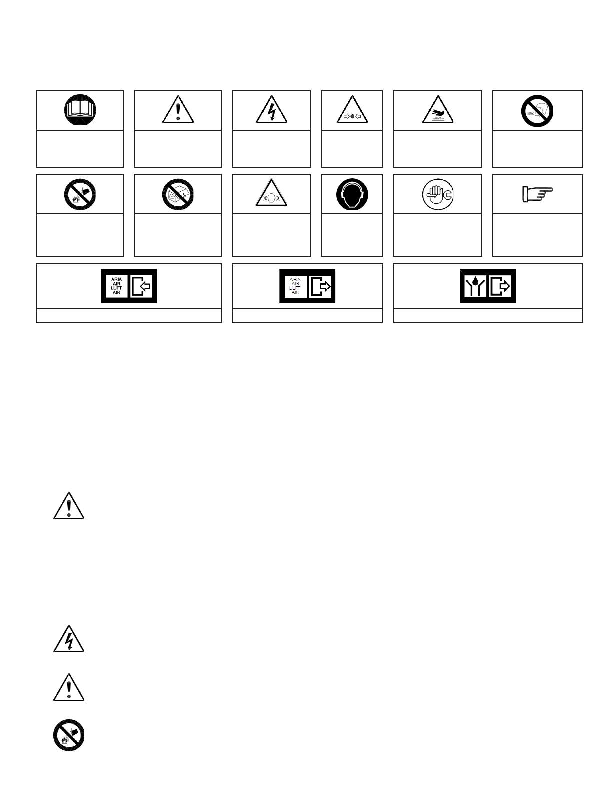
Techniciansthatservicethemachinemustwearhearingandeyeproteconwhileservicingthedryer.
Eachemployeemustselectaproperpersonalprotecondevice(PPD)hearingprotectorsuchas
earmus,earcanalcapsorearplugsinordertopreventpermanenthearingdamageorloss.
MinimumInstallaonRequirements:
+ Selectaclean,dryroomthatisfreeofdustandprotectedfromatmosphericdisturbances.
+ Theequipmentfoundaonmustbesmooth,horizontallylevel,abletobeartheweightofthedryerandvibraon
free
+ Minimumambienttemperatureof+40°F
+ Maximumambienttemperatureof+120°F
+ Allowaclearanceofatleast3’onallsidesofthedryerinordertoeasilyfacilitateallmaintenanceneeds
+ Thedryerisrequiredtobeanchoredtothesupporngsurface
+ Coalescingpre-lterwithdrainmustbeinstalled
+ Thelocaonofanairreceivertankwillvarydependingoncompressortypeandapplicaoncondions
Incorrect installaon may void warranty.
NOTE: All piping and electrical connecons should be inspected prior to installaon to ensure they have maintained
their integrity during shipping and locang the dryer.
First,maketheinialconneconsasfollows:
1. Inletpipingincludinganisolaonvalve
2. Outletpipingincludinganisolaonvalve
3. Coalescingpre-lterandparculatepost-lter
Werecommendthedryerbeinstalledwitha0.01micronCLEARPOINT®coalescingpre-lterattheinlet
anda1.0micronCLEARPOINT®parculatepost-lterattheoutlet.Itisrecommendedtoinstallboth
5.0micronand1.0micronltersupstreamofthedryerinordertomaintaintheoperaonallifespanof
theinletltertothedryer.Inaddion,werecommendtheuseofaBEKOMAT®zeroairlossdrainonthe
pre-lterandatallothercondensatecolleconpoints,especiallythoseupstreamofthedryer.
Locatethecoalescingpre-lterasclosetothedryeraspossiblewhilesllmaintainingsucientspaceforroune
maintenanceandservice.Inletairenteringthedryermustpassthroughacoalescingpre-lterinorderremove
entrainedcondensateandoiltopreventfoulingofthedesiccantandmaintainstandardoperaon.Anyliquid
condensateenteringthedesiccantbedwillleadtooverloadingofthedryer,poordewpointperformanceandrapid
deterioraonofthedesiccantmaterial.Anyoilenteringthedesiccantbedmaypermanentlyreducethecapacityofthe
desiccantmaterial.
Desiccantdusttravelingdownstreamofthedryermaycausecontaminaonand/oracceleratedweartoother
componentsandequipment.Therefore,aparculatepost-ltershouldbeprovidedtopreventdesiccantdustfrom
travelingdownstream.Acvatedaluminaisconsideredanuisancedustandproperprecauonsshouldbetakenwhen
handlingdesiccant(refertoapplicableMSDSsheet).
4. IMPORTANT!Bypasspipingisnecessary.Onlybubbleghtvalvesshouldbeused.
5. Maketherequiredelectricalconnecons;pleasereferthetypeplateofyourdryer.Theenduseris
responsibleforprovidingshortcircuitproteconforthedryer.
6. Pointsofaccessshouldbeprovidedupstreamanddownstreamofthedryerforperiodicmonitoring
ofdewpoint,pressureandtemperaturepriortonalizingtheinstallaon.Takingperiodicdew
pointmeasurementsjustdownstreamofthedryergivesthebestindicaonofwhetherthedryer
isperformingopmally.WerecommendusingMETPOINT®instrumentaontoensureaccurate
measurements.
7. Allpipingmustbeadequatelysupportedandatleastofequalsizetothedryerconnecons.

DRYPOINT® XC Series Heatless Regenerated Dryers: IOM10003 (Rev.I)
6
Opmal Installaon Diagram
1AirCompressor
2AerCooler
3CLEARPOINT®InlineWaterSeparator
4CLEARPOINT®5.0Micron(GradeG)Filtraon
5ReceiverTank
6CLEARPOINT®1.0Micron(GradeF)Filtraon
7DRYPOINT®XCeDesiccantDryerwithCLEARPOINT®PreandPost-ltraon
8DryAirOutlet
9CondensateDrainagePointsforBEKOMAT®
Opmalinstallaoniswithmoderately-sizedreceiversattheinletandoutletsideofthedryer.Thisallowsforthe
addionalfreecoolingandmoisturecolleconandmoreconsistentdryerinletowprovidedbyanupstreamreceiver,
whileprovidingthemostreliableshopairsupplyduetothedownstreamreceiver.
Undernocircumstancesshouldthepeakdemandairowexceedthemaximumratedairowofthedryer.
We recommend the dryer be installed with a 0.01 micron CLEARPOINT® coalescing pre-lter at the
inlet and a 1 micron CLEARPOINT® parculate post-lter at the outlet. It is recommended to install
both 5 micron and 1 micron lters upstream of the dryer in order to maintain the operaonal lifespan
of the inlet lter.
2.4 Mounted Filters with Bypass
MountedFilterswithBypassisanoponalsetupforDRYPOINTXC.Thethree
valvesystembypassallowsfortheowofairtobeuninteruptedwhileservicing
orcomplengpreventavemainnancesuchas:
+ Exchangepre-andpost-lters
+ Servicesexhaustsilencers
+ Changedesiccant

DRYPOINT® XC Series Heatless Regenerated Dryers: IOM10003 (Rev.I)
7
3. TECHNICAL SPECIFICATIONS AND GENERAL FUNCTION
3.1 Technical Data by Model Size
DRYPOINT® XCe Model Size 80 100 120 160 200 250 300 400 500 650 800
FlowRate scfm 80 100 120 160 200 250 300 400 500 650 800
Inlet/OutletConnecon in.(NPT-F) ¾ 1 1 1 ¼ 1 ¼ 1 ½ 1 ½ 2 2 2 ½ 2 ½
Height(A) in. 54 64 64 68 68 69 69 71 73 74 71
Width(B) in. 37 38 38 40 40 45 45 49 53 57 61
Depth(C) in. 22 23 23 26 26 30 30 35 36 40 43
AdsorbentMaterial AcvatedAlumina ⅛”
TotalperDryer Lbs. 132 167 167 262 262 384 384 539 715 917 1114
OutletPressureDewPoint °F -40
MinimumAmbientTemperature °F 40
MaximumAmbientTemperature °F 120
StandardInletAirTemperature °F 100
MaximumInletAirTemperature °F 120
MinimumAirPressure psig 60
StandardAirPressure psig 100
MaximumAirPressure psig 150
Opmalinstallaoniswithmoderatelysizedreceiversattheinletandoutletsideofthedryer.Thisallowsforthe
addionalfreecoolingandmoisturecolleconandmoreconsistentdryerinletowprovidedbyanupstreamreceiver,
whileprovidingthemostreliableshopairsupplyduetothedownstreamreceiver.
Undernocircumstancesshouldthepeakdemandairowexceedthemaximumratedairowofthedryer.
DryerrangsadheretothefollowinginletcondionsperISO7183,Table2,OponA2:
+ InletCompressedAirTemperature100°F(38°C)
+ InletCompressedAirPressure100psig(7bar)
+ MaximumAmbientAirTemperature100°F(38°C)
+ InletCompressedAirRelaveHumidity100%(Saturated)
SCFMisdenedasthevolumeoffreeairincubicfeetperminutemeasuredat14.5psia(1.013bar)at68°F(20°C)
temperaturewith0%relavehumidity(0WVP).

DRYPOINT® XC Series Heatless Regenerated Dryers: IOM10003 (Rev.I)
8
3.2 Correcon Factors
Correcon Factors
≤ 90°F 95°F 100°F 105°F 110°F 115°F 120°F
60 PSIG 0.70 0.68 0.65 0.60 0.55 0.50 0.46
70 PSIG 0.79 0.77 0.74 0.68 0.62 0.57 0.52
80 PSIG 0.88 0.85 0.82 0.75 0.69 0.63 0.57
90 PSIG 0.97 0.95 0.91 0.84 0.76 0.70 0.64
100 PSIG 1.07 1.04 1.00 0.92 0.84 0.77 0.70
110 PSIG 1.17 1.13 1.09 1.00 0.92 0.84 0.76
120 PSIG 1.25 1.22 1.17 1.08 0.98 0.90 0.82
130 PSIG 1.31 1.27 1.22 1.12 1.02 0.94 0.84
140 PSIG 1.34 1.30 1.25 1.15 1.05 0.96 0.88
150 PSIG 1.39 1.35 1.30 1.20 1.09 1.00 0.91
How to Determine Dryer Capacity at Operang Condions: How to select the dryer for actual condions:
ADJUSTEDCAPACITY= ADJUSTEDCAPACITY=
StandardFlowRatexCorreconFactor SystemFlowRate÷CorreconFactor
Example: Example:
DryerModel: DRYPOINT®XCe250 SystemFlowRate: 300scfm
StandardFlowRate: 250scfm OperangCondions: 130psig/100°F
OperangCondions: 110psig/110°F ADJUSTEDCAPACITY= 300scfm÷1.22=246 scfm
ADJUSTEDCAPACITY= 250scfmx0.92=230 scfm SelectDryerModel: DRYPOINT®XCe250
3.3 General Funcon
TheDRYPOINT®Xheatlessdesiccantdyerseriesareedwithtwopressurevessels,posionedparalleltooneanother
andlledwithadsorponmaterial(⅛”acvatedaluminaasstandard).Whilethecompressedairisdriedinonetower,
thesaturateddesiccantisregeneratedinthesecond.Aminimalporonofthetreatedairisusedfortheregeneraon
processandexpelledalongwiththecondensate,throughthesilencers.
Thesaturatedinletairiscycledthrougheachofthetwodesiccantbedsinanalternangsequencewhereonebedison-
lineatfulllinepressureandow,adsorbingthewatervapor.Thisisthedryingbed.
Theotherbedisthenconsideredtobeinano-linestateatatmosphericpressureandisbeingregeneratedbya
depressurizedporonofthedried,treatedoutletair(purgeair).Thisistheregenerangbed.
Thepurgeairisroutedfromthedryoutletairthroughthepurgeowcontrolvalve,desiccantbed,purgeexhaustvalve
andnallyexhaustedtoatmospherethroughsilencerstonishtheregeneraonprocess.Purgeairconsumponis
generallythehighestcostinvolvedwithoperangaheatlessadsorpondryerandisnon-recoverable.Therefore,theair
systemwherethedryerisinstalledmustaccountforthisusage(approximately15%oftheinletairow).
Justbeforethefreshlyregeneratedbedisbroughttoanon-linestatetobecomethedryingbed,itisslowlypressurized
fromatmosphericpressureuptolinepressure.Thisisthere-pressurizaonstepthatpreventsdesiccantbeduidizaon
(bedliing)anddusng.Thedesiccantbedswillnowswitchfunconswherethefreshdesiccantbedisnowdryingand
thesaturatedbedisnowregenerang.
Thiscyclewillconnueautomacallyunlessthedryerisshutdown.
Alldesiccantdryersworkusingtheprincipleofadsorpon,whichistheprocessbywhichwatervaporisremovedfrom
thecompressedairbeingdried.Alldesiccantmaterialtypesareadverselyaectedbycontaminantsincludingoil,

DRYPOINT® XC Series Heatless Regenerated Dryers: IOM10003 (Rev.I)
9
aerosols,dirt,rust,scaleandliquidwater.Ifcontaminated,thedesiccantmaterialwillloseitsadsorponpropriees.
Duringnormaloperaon,thedesiccantwillreleaseasmallamountofdust(asnepowder)thatisparcularlyabrasive
andcanbeextremelydamagingtodownstreamcomponentsandusers.
Forthisreason,itishighlyrecommendedthatthedryerisequippedwithtwohigh-eciencyCLEARPOINT®lters:
+ 0.01 micronltraongradecoalescingpre-lterwithdierenalpressuregaugeandeitheraoatdrainor
BEKOMAT®
+ 1.0 micronltraongradeparculatepost-lter(dierenalgaugeoponal)andwithamanualdrain.
3.4 Flow Diagram
Number Name Number Name
1InletValve(NormallyOpen) 8SolenoidBlock
2PurgeExhaustValve(NormallyClosed) 9PilotAirFilterandRegulator
3ExhaustSilencer 10 VesselPressureGauge
4OutletCheckValves 11 DewPointSensor(Oponal)
5PressureReliefValve 12 EnergyManagementSystem%RH
6PurgeControlValve 13 Pre-lterwithFloatDrain
7OponalBEKOMATZeroLossDrain 14 Post-lterwithManualDrain

DRYPOINT® XC Series Heatless Regenerated Dryers: IOM10003 (Rev.I)
10
3.5 Cycle Operaon
Thecyclemeisfactorysetforoperaonat
100psiginletairpressureand100°Finletair
temperature.
+ 10minutesfor-40°F(-40°C)
IV-A=InletValve,VesselA
IV-B=InletValve,VesselB
PV-A=PurgeValve,VesselA
PV-B=PurgeValve,VesselB
Pressurizaon Sequence
Aerproperpressurizaonofthedryertheoperatormaybeginthestart-up.Duringthestart-upphase,both
purgeexhaustvalvesPVAandPVB(5and6)areclosedforaperiodof70-secondstohelpguaranteethecomplete
pressurizaonofthedryer.
Step1-2 ThepurgeexhaustvalvePV-B(2)ispoweredopentodepressurizevesselforregeneraon.
SimultaneouslythesolenoidvalveIV-B(1)ispoweredclosedbythepneumactowerselecon.The
compressedairowisdirectedtovesselA,wherethedesiccantmaterialadsorbsthehumiditydownto
thetargetdewpoint.Throughthepurgecontrolvalve(6),asetamountofdryairdischargedfromtower
AisexpandedintovesselB.Thisdryair,whilecrossingVesselB,driestheadsorbentmaterialandthe
nowmoisture-ladenpurgeairisdischargedthroughthePV-Bvalve(2)andexitsthesilencers(3).Atthe
endofthisstagetheadsorponmaterialofvesselBiscompletelyregenerated.
Step3 ThepurgeexhaustvalvePV-B(2)isclosedandthenthroughthePurgeControlValve(6)vesselBisre-
pressurizedtotheworkingpressure.Thesumofsteps1-2+3equalsahalfcycleme.
Step4-5 ThepurgeexhaustvalvePV-A(2)ispoweredopentodepressurizevesselforregeneraon.
SimultaneouslythesolenoidvalveIV-B(1)ispoweredclosed.Thecompressedairowisdirectedto
vesselB,wherethedesiccantmaterialadsorbsthehumiditydowntothetargetdewpoint.Throughthe
purgecontrolvalve(6)adenedamountofdryaircomingoutfromtowerAisexpandedintovesselB.
ThisdryairwhilecrossingvesselA,driestheadsorbentmaterialdraggingawaythehumiditythrough
thePV-Avalve(2)andthesilencers(3).AttheendofthisstagetheadsorponmaterialofvesselAis
completelyregenerated.
Step6 ThepurgeexhaustvalvePV-A(8)isclosedandthenthroughthePurgeControlValve(6)vesselAisre-
pressurizeduptotheworkingpressure.Thesumofstep4-5+6equalsahalfcycleme.Attheend,the
cyclestartsupagainfromstep1-2.
NOTE: The cycles are symmetrical, therefore 1-2=4-5 and 3=6

DRYPOINT® XC Series Heatless Regenerated Dryers: IOM10003 (Rev.I)
11
4. PURGE VALVE ADJUSTMENT
Thepurgeowcontrolvalvemustbesettomatchtheinletpressureofthedryer.Thevalvemustbeopenedtothe
correspondingnumberofturnsreferencedinthetablebelow.
+ Always base the pressure adjustment on the lowest operang pressure of the system
+ The inial seng from factory is for 100 psig operaon
Theprocedureforadjusngthepurgeowcontrolvalveisasfollows:
Rendereddrawingofpurge
owcontrolvalve
Turnknobclockwise
(totheright)toclose
Turnknobcounterclockwise
(tothele)toopen
Theknobstemofthevalveisnumberedandacompleteturnisconsideredturningthecontrolknob360°fromnumber
tonumber.Thenumberofturnsexpressedinthetablebelowisbasedonthenumberofturnsfromtheclosedposion.
1. Loosenthescrewusingaatheadscrewdriverorallen-head
2. Turnthepurgeowcontrolvalveclockwiseunlthestoppingpoint–thevalveisnowclosed
3. Turnthepurgeowcontrolvalvecounterclockwiseunlthesengforthedesiredoperangpressurevalueis
reached–thevalveisnowopen
4. Tightenthescrewusingaatheadscrewdriverorallen-head
Purge Adjustment Table
ApproximatePurgeValveSeng(numberofturnstoopen)
Purge Flow
Rate [scfm]
Dryer Inlet Pressure
Dryer 80 psig 90 psig 100 psig 110 psig 115 psig
XC80 16 3.5 3.2 3.1 2.9 2.9
XC100 20 4.0 3.8 3.7 3.6 3.5
XC120 24 5.5 5.3 5.0 4.8 4.5
XC160 32 5.9 5.7 5.5 5.4 5.4
XC200 40 6.5 5.6 5.2 4.8 4.7
XC250 50 7.0 6.5 6.0 6.0 5.5
XC300 60 8.0 7.5 7.1 6.9 6.8
XC400 80 3.6 3.5 3.3 3.2 3.1
XC500 100 4.5 4.4 4.2 4.1 4.0
XC800 160 6.2 4.9 4.7 4.6 4.5
Consultafactoryrepresentaveformoreinformaon.

DRYPOINT® XC Series Heatless Regenerated Dryers: IOM10003 (Rev.I)
12
5. START-UP
5.1 Vericaon Prior to Start-up
Verifythattheoperangparametersmatchwiththeacceptablerangesindicatedonthedataplateofthe
dryer(voltage,frequency,airpressure,airtemperature,ambienttemperature,etc.).Thisisnotthesameas
theASMEUWplateonthevesselsandmaybelowerthanwhatisstampedontheASMEUWplate.
Beforedelivery,eachdryerissubmiedtoaccuratetestssimulangrealoperangcondions.Nevertheless,theunit
couldbedamagedduringtransportaon.Therefore,wesuggestcheckingtheintegrityofthedryeruponarrival(see
page4)andobservingthedryerduringthersthoursofoperaon.
Thestart-upmustbeperformedbyqualiedpersonnelonly.Itismandatorythatthequaliedperson
inchargewillverifysafeoperaonalcondionscomplyingwiththelocalsafetyandaccidentprevenon
requirements.
Thesamequaliedpersonwillberesponsiblefortheproperandsafeoperaonofthedryer.Neveroperate
thedryerifallpanelsarenotproperlyinplaceorifanycomponentryismissingorappearsdamaged.
Servicetobeperformedbyqualiedpersonnelonly.Theenduserisresponsibletoensurethatthedryer
willneverbeoperatedwithpressurethatexceedsthemaximumpressurerangoftheunit.Operangthe
dryeratapressurehigherthanthemaximumrangcouldbedangerousforboththeoperatorandthe
machine.
Theinletairtemperatureandairowrateenteringthedryermustbewithinthelimitsindicatedonthedataplate.
Installaonprecauonsmustbetakeninordertolimitthevibraonthatcanoccurduringtheoperaonofthedryer.
Therefore,werecommendusingexibleconnecngpipesthatareabletoinsulatethedryerfrompossiblevibraons
originangfromthepipeline.
Theconnecontothemainpoweristobecarriedoutbyqualiedpersonnel,andthesafetyprotocolmust
complywithlocalrulesandlaws.
Beforeconnecngtheunittotheelectricpower,verifythatthevoltageandthefrequencyavailableonthemains
correspondtothedataonthedataplateofthedryer.Intermsofvoltage,a±5%toleranceisacceptable.Thewire
sizefeedingthedryermustcomplywiththeconsumponofthedryer,whilekeepingintoaccountalsotheambient
temperature,thecondionsofthemainpowerjunconbox,thelengthofthewire,andtherequirementsenforcedby
theNaonalElectricCode.
Itismandatorytoensuretheconnecontothegroundterminal.
Thecondensateisdischargedatthesamepressureastheairenteringthedryer.Neverpointthe
condensatedraindischargetowardsanybody.
Connectandproperlyfastenthecondensatedraintoacolleconsystemorcontainer.Theoutletcondensatehose
cannotbeconnectedtopressurizedsystems.
DO NOT DISPOSE OF CONDENSATE INTO THE ENVIRONMENT
Thecondensatecollectedinthedryercontainsoilparclesreleasedintotheairstreambythecompressor.
Disposeofthecondensateinamannercompliantwithalllocal,stateandFederalrulesandregulaons.We
highlyrecommendtheinstallaonofeitheraQWIK-PURE®orÖWAMAT®oil-waterseparatoratthenal
colleconpointforallcondensatedischargelineswithinthefacility(i.e.fromthemainheader).

DRYPOINT® XC Series Heatless Regenerated Dryers: IOM10003 (Rev.I)
13
5.2 Start-up Procedures
Duringtherststart-uporstart-upaeralongperiodofinacvityorfollowingmaintenance,thetechnician
mustcomplywiththeinstruconsbelow.Thestart-upmustbeperformedbyqualiedpersonnelonly.
Theemployeethatoperatesthemachinemustwearhearingandeyeproteconbeforeoperangthedryer.
Eachemployeemustselectaproperpersonalprotecondevice(PPD)hearingprotectorsuchasearmus,
earcanalcapsorearplugsinordertopreventpermanenthearingdamageorloss.
Start-up Sequence
+ Pleasereadandunderstandtheenremanualbeforeoperangthedryer
+ Verifythefactorysengs
+ Verifythewiringdiagramsthatpertaintoyourunitandensurethecorrectpowersupplyisconnected
Do not energize the circuit at this me
+ Verifythatpropershortcircuitproteconhasbeenprovidedfollowingallapplicablecodesandregulaons
+ Verifythatallthestepsofinthepreviouschaptersrelangtoinstallaonhavebeenobserved
+ Verifythattheconnecontothecompressedairsystemiscorrect
+ Verifythatthecondensatedrainpipeisproperlyfastenedandconnectedtoacolleconsystemorcontainer
+ Removeanypackagingandothermaterialthatmightobstructtheareaaroundthedryer
Beforestarngthedryeryourcompressorshouldberunning,yourcompressedairsystempressurizedandthedryer
bypassedandnotyetpressurized.
1. Withthedryerbypassedandinisolaon(seepage14)
2. SLOWLYopentheinletisolaonvalveallowingcompressedairintothedryer.Itiscricalthatthedryer
bepressurizedslowlytopreventuidizaonofthedesiccantbed.Keeptheoutletisolaonvalveclosed
atthisme.
3. SLOWLYopentheoutletisolaonvalve.Allvalvesarenowintheiropenposionsandcompressedairis
owingthroughbothtowersanddownstream.
4. Closethedryerbypassvalve.Thebypassvalvemustbebubbleghttopreventanymoisturefrom
contaminangthedryairoutletfromthedryer.
5. Pluginthedryerandenergizetheelectricalcircuit–thedryerisnowON.
6. Verifythatthecontrollerison.
7. Checkallpipingforcompressedairleaks.
8. Testthecondensatedrainonthepre-lter.
9. Aer1-minutesfromstart-uptheadsorpontowerBwillbedepressurized.
10. Waitforthedryertomake10fullcycles(i.e.thedepressurizaonfromtowerAtotowerB).
11. Thedryerwillmaketherst5cyclesshortcycles,runningat50%runmewithoutregardfordewpoint.
12. Thepressureswingcyclesoccurs,every5minutes(outletdewpointof-40°F).
NOTE: During the rst days in operaon, the dew point cannot be guaranteed because the adsorpon material can
contain humidity from storage. At the rst start-up or start-up aer a long inacvity period or following maintenance
shutdowns, we recommend operang the dryer at a reduced nominal ow of 50% during the rst two days.

DRYPOINT® XC Series Heatless Regenerated Dryers: IOM10003 (Rev.I)
14
5.3 General Operaon
+ Thedryermayrequireupto48-hoursofoperaontoreachnormaloperangoutletdewpoint.Therefore,
indicatorsandalarmsdonotneedtoberecognizedduringthisme.Applicaonswhereadewpointlowerthan
-40°Fisneeded,mayrequireaddionalmetoreachequilibrium.
+ Thedryerwillnotperformwithoutproperlysizedandinstalledpre-ltraon,condensatedrainageandcorrect
purgeowadjustment.
+ Aertheinialstart-upsomedusngmayoccur.Thisisnormalandwilldiminishwithme,althoughmay
acceleratetherstmaintenanceintervaloftheexhaustvalves,exhaustsilencersandpost-lterelement.
+ Exhaustvalvesandsilencersmayhavetobecleanedduetodusngfromshippingandtheinialstart-up,and
shouldbecleanedregularlytoensureproperoperaon.Post-lterelementsshouldalsobepartofaregular
preventavemaintenanceschedule.
+ Neverservicethedryerorlterswithoutrstrelievingpressurefromthedryer.
+ Adesiccantdryershouldneverbepressurizedordepressurizedsuddenly.Thiswillcausedegradaonand
dusngofthedesiccantbed.
+ Thedryerisdesignedforamaximumoperangpressureof150psigasstandard.
6. ISOLATION AND SHUT DOWN PROCEDURES
Usersoperangthemachinemustwearhearingandeyeprotecon.Eachemployeemustselectaproper
personalprotecondevice(PPD)hearingprotectorsuchasearmus,earcanalcapsorearplugsinorderto
preventpermanenthearingdamageorloss.
Isolaon
1. Allowthedryertoreachitsre-pressurizaonstepandfullyre-pressurize.
2. Oncefullyre-pressurized,removepowerfromthedryer.
3. Openthebypassvalve.
4. Closetheoutletisolaonvalve.
5. Closetheinletisolaonvalve.
Depressurizaon and Shut Down
1. Openthebypassvalve.
2. Closetheoutletisolaonvalve.
3. Closetheinletisolaonvalve.
4. Allowthedryertoconnuetorun.Duringthenormaloperangcyclebothtowerswillblowdownand
depressurize.
5. Disconnectthepowertothedryer.
6. Openthemanualballvalvesonanylterswithmanualballvalvestoallowfulldepressurizaon.Also,
leavemanualballvalvesonlteropenduringmaintenanceandservice.
IMPORTANT!Alwaysremoveallpressureanddisconnectallpowerbeforeservicingthedryer.
Torestartthedryer,followthestart-upprocedureinSecon5.START-UP

DRYPOINT® XC Series Heatless Regenerated Dryers: IOM10003 (Rev.I)
15
7. CONTROLLER INFORMATION AND OPERATION
7.1 Display Overview
TheLEDilluminatedPIDcontrollerinterfacesbetweenthedryerandtheoperator(shownabove).Thefollowingpages
thedetailedinformaonaboutthecontroller’ssengsandoperaon.
ThecontrollerhasatotalofnineLEDstoinformtheoperatoritsstepinoperaon:
+ Twocheckvalvesindicangthedireconofairowoutofthedryer
+ Onepurgevalveindicatorusedduringregeneraon
+ TwoLEDsareusedtoindicatetheacvedryertowerduringoperaon
+ FourLEDsindicatepurgeexhaustvalveandinletvalvePV-andIV-
ThecontrollerhastwoaddionalLEDsusedtoindicatepowerandserviceintheupperlecornerofthedisplayas
shownbythecorrespondingicons.Duringnormaloperaon,thepowerLEDisgreenandtheserviceindicatorLEDiso.
7.2 Controller Startup
Itisimportanttonotethatthecontrollerisprogramedtorunvemesinsuccessionforashortcycle.Thatisa50%
shorterrunmeswithoutconsideraonofthedewpointinputtobringthedryertoadenedstate.Aerthisstartup
procedurethedeviceisinnormaloperaonmode.
Duringstatupthecompressorsynchronizaoninputisalsoacve.
7.3 Controller Inputs
ThecontrollerandhousingprovidethreeM12andtwoM16glandsonforitsinput/outputconneconlines.Forinput,
theconneconsare:
+ Powercable
+ Compressor-synchronizaonsignal

DRYPOINT® XC Series Heatless Regenerated Dryers: IOM10003 (Rev.I)
16
Theinput“compressorsynchronizaon”,ismeanttosynchronize
thedryerwithswitchingONandOFFofthecompressor.Hence,it
preventsasituaonwherethedryerconnuestooperateanduse
rinsingairfromthecompressedairnetworkthoughthereisnosupply
ofcompressedair.Incasethevoltage(120VAC-Input)dropsatthe
input,thepurgeexhaustvalveisimmediatelyclosed.
Aerthecompressorsignalcomesbackonline,thedryingcycleis
connuedfromthesamepoint,meaningthatthelastopenvalvealso
opensagain.Notetwoexcepons:
+ Thisisnotvalidiftheremainingregeneraonmeislessthan
30seconds,inwhichcaseitimmediatelyswitchesovertothe
otherdryingcolumn,whichmeanstheothervalveisopened.
+ Ifthecompressorisswitchedoformorethan24hours,
thenthedeviceisstartedwithveshortfullNemacyclesas
thoughtheoperangvoltagehasbeeninterrupted(i.e.as
aerRESET).
7.4 Controller Outputs
Thecontrolleroutputsinformaontwoways,one,tothecontroller
display,theother,tothedryersystemthroughthehousingglands:
+ PurgeExhaustValveA
+ PurgeExhaustValveB
Thecontrolleroutputsthedryer’soperaonalsteptothecontroller
displayLEDindicators.Thisindicatestheacvatedvalvesanddrying
tower.Inaddion,thepowerlightandserviceindicatoraredisplayed.
Thecontrolleroutputsanelectricalsignaltothetowerselector
solenoidvalveandenergizestheappropriatevalvesbasedondryer’s
stepofoperaon.
7.5 Controller Sengs
ThecontrollerunithasatotalofeightDIPswitcheswiththefollowingparameters:
+ ThreeDIPswitchesareusedtosetthetowerregeneraonme
+ TwoDIPswitchesareusedtosetthepressurebuild-upme
+ OneDIPswitchusedforfutureexpansion
+ OneDIPswitchalignsthecontrollerwiththecompressorsync
+ OneDIPswitchusedforfutureexpansion
BelowisapictureoftheDIPswitchcontrolinterface:

DRYPOINT® XC Series Heatless Regenerated Dryers: IOM10003 (Rev.I)
17
Thecontroller’seightDIPswitchesaredetailedinthefollowingsecon.Theseswitchesareadjustablebutshouldonly
bedonesobyaqualiedperson.
7.5.1 Regeneraon Time (1, 2, 3)
Theregeneraonmeisthemeselectedforsteps1-2detailedinSecon3.5.ThethreeDIPswitchescanbeadjusted
toeight(8)seleconmesbetween2.5and6minutesinincrementsof30-secondsasfollows:
+ 000 2.5minutes
+ 100 3.0minutes
+ 010 3.5minutes
+ 110 4.0minutes(factoryseng)
+ 001 4.5minutes
+ 101 5.0minutes
+ 011 5.5minutes
+ 111 6.0minutes
7.5.2 Re-Pressure Build-Up Time (4, 5)
There-pressurebuild-upmeisthemeselectedforstep3inSecon3.5.ThetwoDIPswitchescanbeadjustedtofour
(4) regeneraonmesbetween60and120secondsin20-secondincrementsasfollows:
+ 00 60seconds(factoryseng)
+ 10 80seconds
+ 01 100seconds
+ 11 120seconds
7.5.3 Expansion (6)
ThisDIPswitchisnotcurrentlyinuseandshouldbesettoOFF,‘0’.
7.5.4 Compressor Sync (7)
Thecompressorsynctothecontrollerisdetailedinsecon7.3.Itcanbesettoeithertoan‘ON’or‘OFF’posion.
+ 0 OFF-compressorissynched
+ 1 ON-compressornotsynched(factoryseng)
7.5.6 Expansion (8)
ThisDIPswitchisnotcurrentlyinuseandshouldbesettoOFF,‘0’.
7.5.7 Factory Default Sengs
ThefactorydefaultsengsoftheDIPswitchesareasfollows:
Purge Air Time 4.0minutes(1,1,0)
Re-Pressure Build-Up 60seconds(0,0)
Expansion OFF(0)
Compressor Sync ON(1)
Expansion OFF(0)

DRYPOINT® XC Series Heatless Regenerated Dryers: IOM10003 (Rev.I)
18
7.6 Service Reset Buon
Disconnectdryerfrompower.Withthedryerdisconnectedfromthepowersourcepresstheresetbuon
andholditandplugthedryerbackintoitspowersource.Aerthatthemerisresetto8000hrs.
Aer 360-days of the service indicator LED will ash amber indicang that service is due, and aer 400-
days the LED will ash red indicang that service is overdue.
7.7 Power Requirements
Thecontrolleroperateson100-120VAC/50-60Hz.TheunitsareshippedwithaninstalledstandardUS120voltcord
forconvenience.Beforestarngupthemachineitisnecessarytohaveaqualiedelectricianreviewtheelectrical
requirementsschemacandinstalltotheNaonalElectricCode.PleaserefertoSecon12.
The oponal BEKOMAT® on the pre-lter at the dryer inlet is supplied according to the power voltage
indicated in the order; verify its compability with the informaon given on the type plate.
This manual suits for next models
10
Table of contents
Other Beko Dryer manuals

Beko
Beko DC 7230 BX1 User manual

Beko
Beko DTGC 8101 W User manual

Beko
Beko DCU 7230 X User manual

Beko
Beko B5T60230M User manual

Beko
Beko DC 7112 W User manual

Beko
Beko BTBC44XB1 User manual

Beko
Beko DCU 9203020BX User manual

Beko
Beko DS7534RX3 User manual

Beko
Beko DPHY9P46W User manual

Beko
Beko B5T68259M User manual

Beko
Beko DHR83431W User manual

Beko
Beko DRYPOINT AC Series User manual

Beko
Beko DCUR 701 W User manual

Beko
Beko 600873CH User manual

Beko
Beko DCU 7230 User manual

Beko
Beko BDCB8020W User manual

Beko
Beko DC8230A User manual

Beko
Beko DS 9430 SX User manual

Beko
Beko B5T89243W User manual

Beko
Beko DPS 7343 X User manual