Beko CWB 9560 X User manual

PT
EN ES
CWB 9560 X
Cooker Hood
User Manual

Complies with the WEEE Directive.
This product was manufactured using the latest technology in environmentally friendly conditions.
Please read this user manual first!
Dear Customer,
Thank you for preferring a Beko product. We hope that you get the best results from your product which
has been manufactured with high quality and state-of-the-art technology. Therefore, please read this
entire user manual and all other accompanying documents carefully before using the product and keep
it as a reference for future use. If you handover the product to someone else, give the user manual as
well. Follow all warnings and information in the user manual.
Remember that this user manual is also applicable for several other models. Differences between mod-
els will be identified in the manual.
Explanation of symbols
Throughout this user manual the following symbols are used:
CImportant information or useful hints about
usage.
AWarning for hazardous situations with regard to
life and property.
Does not contain PCB.

3 / 30 EN
Cooker Hood / User Manual
TABLE OF CONTENTS
1 Important instructions for safety and
environment 6-7
2 Installing your appliance 8-9
3 Cleaning and maintenance 10-12
01M-8846173200-4814-04

Fig.1
AB C
Fig.2 Fig.3
Fig.4 Fig.5

Fig.7
Fig.8
Fig.10
Fig.12
Fig.9
Fig.11
Fig.13
Fig.6

Cooker Hood / User Manual
6 / 30 EN
1 Important instructions for safety and environment
General
Carefully read the following impor-
tant information regarding installa-
tion safety and maintenance. Keep
this information booklet accessible
for further consultations. The appli-
ance has been designed for use in
the ducting version (air exhaust to
the outside - Fig.1B), filtering ver-
sion (air circulation on the inside
- Fig.1A) or with external motor
(Fig.1C).
Safety precaution
•Take care when the cooker hood
is operating simultaneously with
an open fireplace or burner that
depend on the air in the environ-
ment and are supplied by other
than electrical energy, as the
cooker hood removes the air from
the environment which a burner
or fireplace need for combustion.
The negative pressure in the en-
vironment must not exceed 4Pa
(4x10⁻⁵ bar). Provide adequate
ventilation in the environment for
a safe operation of the cooker
hood.
Follow the local laws applicable
for external air evacuation.
Before connecting the model to
the electricity network:
•Control the data plate (positioned
inside the appliance) to ascertain
that the voltage and power cor-
respond to the network and the
socket is suitable. If in doubt ask
a qualified electrician.
•If the power supply cable is dam-
aged, it must be replaced with
another cable or a special assem-
bly, which may be obtained direct
from the manufacturer or from the
Technical Assistance Centre.
•This device must be connected to
the mains supply through either a
plug fused 3A or hardwired to a 2
phase spur protected by 3A fuse.
AIn certain circumstances
electrical appliances may
be a danger hazard.
•Do not check the status of the fil-
ters while the cooker hood is op-
erating.
•Do not touch bulbs or adjacent
areas, during or straight after pro-
longed use of the lighting instal-
lation.
•Flambè cooking is prohibited un-
derneath the cooker hood.
•Avoid free flame, as it is damaging
for the filters and a fire hazard.

7 / 30 EN
Cooker Hood / User Manual
1 Important instructions for safety and environment
•Constantly check food frying to
avoid that the overheated oil may
become a fire hazard.
•Disconnect the electrical plug
prior to any maintenance.
•This appliance is not intended for
use by young children or infirm
persons without supervision.
•Young children should be super-
vised to ensure they do not play
with the appliance.
•There shall be adequate ventila-
tion of the room when the range-
hood is used at the same time as
appliances burning gas or other
fuels.
•There is a risk of fire if cleaning is
not carried out in accordance with
the instructions.
Compliance with WEEE regulation and
disposal of the waste product
This appliance conforms to the European Direc-
tive EC/2002/96, Waste Electrical and Electronic
Equipment (WEEE). By making sure that this ap-
pliance is disposed of in a suitable manner, the
user is helping to prevent potential damage to the
environment or to public health.
The symbol on the product or on the ac-
companying paperwork indicates that
the appliance should not be treated as
domestic waste, but should be delivered
to a suitable electric and electronic ap-
pliance recycling collection point. Follow local
guidelines when disposing of waste. For more in-
formation on the treatment, re-use and recycling
of this product, please contact your local authority,
domestic waste collection service or the shop
where the appliance was purchased.

Cooker Hood / User Manual
8 / 30 EN
•Assembly and electrical connections must
be carried out by specialized personnel.
•Wear protective gloves before proceeding
with the installation.
Electric Connection:
•The appliance has been manufactured as a
class II, therefore no earth cable is necessary.
The plug must be easily accessible after the
installation of the appliance. If the appliance is
equipped with power cord without plug, a suit-
ably dimensioned omnipolar switch with 3 mm
minimum opening between contacts must be
fitted between the appliance and the electricity
supply in compliance with the load and current
regulations.
•The connection to the mains is carried out as
follows:
BROWN = L line
BLUE = Nneutral.
•The minimum distance between the support
surfaces of the cooking pots on the cooker top
and the lowest part of the cooker hood must be
at least 65 cm. If a connection tube composed
of two parts is used, the upper part must be
placed outside the lower part.
Do not connect the cooker hood exhaust to the
same conductor used to circulate hot air or for
evacuating fumes from other appliances gener-
ated by other than an electrical source. Before
proceeding with the assembly operations, re-
move the anti-grease filter(s) (Fig.5) so that the
unit is easier to handle.
•In the case of assembly of the appliance in the
suction version prepare the hole for evacuation
of the air.
•We recommend the use of an air exhaust tube
which has the same diameter as the air exhaust
outlet hole. If a pipe with a smaller diameter
is used, the efficiency of the product may be
reduced and its operation may become noisier.
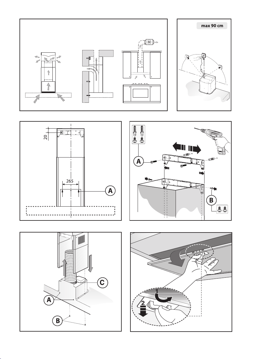
Fixing to the wall:
Drill the holes Arespecting the distances indi-
cated (Fig.2). Fix the appliance to the wall and
align it in horizontal position to the wall units.
When the appliance has been adjusted, definitely
fix the hood using the screws A(Fig.4). For the
various installations use screws and screw an-
chors suited to the type of wall (e.g. reinforced
concrete, plasterboard, etc.).
If the screws and screw anchors are provided
with the product, check that they are suitable for
the type of wall on which the hood is to be fixed.
Fixing the decorative telescopic
flue:
Arrange the electrical power supply within the
dimensions of the decorative flue. If your appli-
ance is to be installed in the ducting version or
in the version with external motor, prepare the air
exhaust opening. Adjust the width of the support
bracket of the upper flue (Fig.3). Then fix it to the
ceiling using the screws A(Fig.3) in such a way
that it is in line with your hood and respecting the
distance from the ceiling indicated in Fig.2. Con-
nect the flange Cto the air exhaust hole using a
connection pipe (Fig.4). Insert the upper flue into
the lower flue.
Fix the lower flue to the hood using the screws B
provided (Fig.4), extract the upper flue up to the
bracket and fix it with the screws B(Fig.3). To
transform the hood from a ducting version into a
filtering version, ask your dealer for the charcoal
filters and follow the installation instructions.
2 Installing your appliance

9 / 30 EN
Cooker Hood / User Manual
2 Installing your appliance
Filtering version:
Install the hood and the two flues as described in
the paragraph for installation of the hood in duct-
ing version. To assemble the filtering flue refer to
the instructions contained in the kit. If the kit is
not provided, order it from your dealer as acces-
sory. The filters must be applied to the suction unit
positioned inside the hood.They must be centered
by turning them 90 degrees until the stop catch is
tripped (Fig.6).

Cooker Hood / User Manual
10 / 30 EN
3 Operating your appliance
•We recommend that the cooker hood is
switched on before any food is cooked. We also
recommend that the appliance is left running
for 15 minutes after the food is cooked, in order
to thoroughly eliminate all contaminated air.
The effective performance of the cooker hood
depends on constant maintenance; the an-
ti-grease filter and the active carbon filter both
require special attention.
•The anti-grease filter is responsible retain-
ing the grease particles suspended in the air,
therefore it is subject to clogging with variable
frequency according to the use of the appliance.
•To prevent the danger of possible fires, at least
every 2 months one must wash the anti-grease
filters by hand using non-abrasive neutral liquid
detergents or in the dishwasher at low temper-
atures and on short cycles.
•After a few washes, color alterations may occur.
This does not give the right to claim their re-
placement.
•The active carbon filters are used to purify
the air that is sent back into the room and its
function is to mitigate the unpleasant odours
produced by cooking.
•The non-regenerable active carbon filters must
be replaced at least every 4 months. The satura-
tion of the active charcoal depends on the more
or less prolonged use of the appliance, on the
type of kitchen and on the frequency with which
antigrease filter is cleaned.
•Before remounting the anti-grease filters
and the regenerable active charcoal filters
it is important that they are completely dry.
•Clean the hood frequently, both internally
and externally, using a cloth dampened
with denatured alcohol or neutral liquid
detergents that are non abrasive.
•The lighting .system is designed for use during
cooking and not for the prolonged general light-
ing of the room. The prolonged use of the light-
ing system significantly decreases the average
duration of the bulbs.
•If the appliance is equipped with courtesy lights
it is possible to use them for general room light-
ing for a prolonged amount of time.
A
The non-compliance with the
hood cleaning warnings and with
the replacement and cleaning of
the filters entails risk of fires. One
therefore recommends keeping to
the suggested instructions.
Replacing LED lamps (Fig.7):
If the appliance version is with LED lamps, the in-
tervention of a specialised technician is necessary
to replace them.
Replacing halogen light bulbs
(Fig.8):
To replace the halogen light bulbs B, remove the
glass pane Cusing a lever action on the relevant
cracks. Replace the bulbs with new ones of the
same type.
ADo not touch the light bulb with bare
hands.
Replacing the halogen/incandescent
lamps (Fig.9):
Only use lamps of the same type and Wattage in-
stalled on the device.

11 / 30 EN
Cooker Hood / User Manual
3 Operating your appliance
Commands (Fig.10) mechanical the
key symbols are explained below:
A= LIGHT
B= OFF
C= SPEED I
D= SPEED II
E= SPEED III
Commands luminous (Fig.11) the
key symbols are explained below:
A= LIGHT
B= OFF
C= SPEED I
D= SPEED II
E= SPEED III
F = AUTOMATIC STOP TIMER - 15 minutes (*)
If your appliance has the INTENSIVE speed func-
tion, from speed THREE, press key Efor 2 seconds
and it will be activated for 10 minutes after which
it will return to the previously set speed. When the
function is active the LED flashes. To interrupt it
before the 10 minutes have elapsed, press key E
again. Some models allow activating this function
even with speed one and two.
By pressing key Ffor two seconds (with the hood
switched off) the “clean air” function is activat-
ed. This function switches the appliance on for ten
minutes every hour at the first speed. As soon as
this function is activated the motor starts up at the
first speed for ten minutes. During this time key F
and key Cmust flash at the same time. After ten
minutes the motor switches off and the LED of key
Fremains switched on with a fixed light until the
motor starts up again at the first speed after fifty
minutes and keys Fand Cstart to flash again for
ten minutes and so on.
By pressing any key for the exclusion of the hood
light the hood will return immediately to its normal
functioning (e.g. if key Dis pressed the “clean
air” function is deactivated and the motor moves
to the 2nd speed straight away. By pressing key B
the function is deactivated).
(*) The “AUTOMATIC STOP TIMER” delays
stopping of the hood, which will continue function-
ing for 15 minutes at the operating speed set at
the time this function is activated.
Anti-grease/active charcoal filters
saturation:
•When the Akey flashes with a 2 second fre-
quency the antigrease filters must be washed.
•When the Akey flashes with a 0.5 second
frequency the active carbon filters must be re-
placed or washed depending on the type of filter.
Once the clean filter has been put back one must
reset the electronic memory by pressing the Akey
for approximately 5 seconds until it stops flash-
ing.
Commands (Fig.12):
Push-button A = On/off lights switch.
Push-button B = On/off cooker hood switch.
The appliance switches on at speed level 1, If the
cooker hood is on depress the push-button for 2
sec. to switch off the cooker hood. If the cooker
hood is at speed level 1 it will not be necessary
to depress the push-button to switch the cooker
hood off. Decreases the motor speed.
Display C = Indicates the motor speed level se-
lected and activates the timer.
Push-button D = Switches on the cooker hood.
Increases the motor speed. Touching the key at
3rd speed, the intensive function runs for 10’,
then the appliance go back to work at the original
speed. During this function the display blinks.
Key E = The Timer times the functions on activa-
tion for 15 minutes, after which they are switched
off. The Timer is deactivated by re-pressing Key
E. When the Timer is activated the decimal point
must flash on the display. The Timer cannot be ac-
tivated if the intensive speed is functioning.

Cooker Hood / User Manual
12 / 30 EN
3 Operating your appliance
The “clean air” function is activated by press-
ing key Efor 2 seconds when the appliance is
switched off.
This switches the motor on for 10 minutes every
hour at the first speed.
During functioning a rotary movement of the pe-
ripheral segments must be visualised on the dis-
play.When this time has passed the motor switch-
es off and the fixed letter “C” must be visualised
on the display until the motor re-starts after 50
minutes for another 10 minutes and so on. Press
any key apart from the light keys to return to nor-
mal functioning. Press key Eto deactivate the
function.
Active carbon/grease filter
saturation:
•When display item Cflashes, at a speed where
it alternates with the letter F(e.g. 1 and F), the
grease filters must be washed.
•When display item Cflashes, at a speed where
it alternates with the letter A(e.g. 1 and A), the
active carbon filters must be replaced or washed
depending on the type of filter.
After the clean filter has been positioned correctly,
the electronic memory must be reset by pressing
button Afor approximately 5 seconds, until the
indication For Ashown on the display Cstops
flashing.
Mechanical controls (Fig.12): the
symbols are as follows:
A = LIGHT / ON-OFF key
B = OFF /FIRST SPEED key
C = SECOND SPEED key
D = THIRD SPEED key
If the hood is shut off at first, second or third
speed, when it is turned back on, it will start at the
same speed it was in when switched off.
THE MANUFACTURER DECLINES ALL RE-
SPONSIBILITY FOR EVENTUAL DAMAGES
CAUSED BY BREACHING THE ABOVE WARN-
INGS.

Este aparato es conforme a la normativa sobre
aparatos eléctricos y electrónicos y la gestión
de sus residuos (WEEE).
Este producto se ha fabricado en plantas de fabricación modernas y que hacen uso de procesos respe-
tuosos con el medio ambiente.
Lea el manual del usuario antes de utilizar el aparato
Estimado cliente:
Gracias por elegir un producto Beko. Esperamos que obtenga los mejores resultados de nuestro pro-
ducto ya que ha sido fabricado con gran calidad y con tecnología de última generación. Por tanto, le
aconsejamos que lea con atención este manual del usuario y todos los demás documentos adjuntos
antes de utilizar el producto y que lo guarde para futuras consultas. Si va a entregar este producto a
otra persona, proporciónele el manual del usuario también. Siga todas las advertencias e instrucciones
incluidas en este manual.
Recuerde que este manual de funcionamiento también puede servir para otros modelos. Las diferencias
entre los modelos se describen explícitamente en el manual.
Significado de los símbolos
Los siguientes símbolos se usan en las diversas secciones del presente manual:
CInformación importante y consejos
útiles sobre el uso.
AAdvertencias de situaciones
peligrosas sobre la seguridad de las
personas y las propiedades
No contiene PCB.

Campana Extractora / Manual De Utilización
14 / 30 ES
ÍNDICE
1 Instrucciones importantes para la
seguridad y el medio ambiente 14-15
2 Instrucciones para la instalación 16-17
3 Uso y mantenimiento 18-20

15 / 30 ES
Campana Extractora / Manual De Utilización
Generalidades
Lea atentamente el contenido del
presente libro de instrucciones pues
contiene indicaciones importantes
para la seguridad en la instalación,
el uso y el mantenimiento (Consér-
velo para un posible consulta pos-
terior). El aparato ha sido diseñado
para el uso en versión aspiradora
(evacuación de aire hacia el exterior
– Fig.1B), filtrante (reciclaje del aire
en el interior – Fig.1A) o con motor
exterior (Fig.1C).
Sugerencias Para La Seguridad
•Preste atención si funcionan con-
temporáneamente una campana
aspirante y un quemador o una
chimenea que toman el aire del
ambiente y están alimentados
por energía que no sea eléctrica,
pues la campana aspirante toma
del ambiente el aire que el que-
mador o la chimenea necesitan
para la combustión. La presión
negativa del local no debe supe-
rar los 4 Pa (4x10⁻⁵ bares). Para
un funcionamiento seguro, realice
primero una adecuada ventilación
del local. Para la evacuación ex-
terna, aténgase a las disposicio-
nes vigentes en su país.
Antes de enchufar el modelo a
la corriente eléctrica:
•Controlar los datos de matrícula
(que se encuentran en el interior
del aparato) para constatar que la
tensión y la potencia correspon-
dan a la de la red y el enchufe de
conexión sea idóneo. En caso de
dudas, recurra a un electricista
calificado.
•Si el cable de alimentación está
dañado, se debe cambiar con un
cable o conjunto especial de ca-
bles que puede suministrar tanto
el fabricante como el servicio de
asistencia técnica.
•Conecte el dispositivo a la red de
alimentación a través de un en-
chufe con fusible 3A o a los dos
cables de la línea bifásica prote-
gidos por un fusible 3A.
AEn determinadas circuns-
tancias los electrodomésti-
cos pueden ser peligrosos.
•No intente controlar los filtros
cuando la campana está en fun-
cionamiento.
•Durante el uso prolongado de la
instalación de iluminación o inme-
diatamente después, no toque las
lámparas ni las zonas adyacentes
a ellas.
1Instrucciones importantes para la seguridad y el
medio ambiente

Campana Extractora / Manual De Utilización
16 / 30 ES
1Instrucciones importantes para la seguridad y el
medio ambiente
•Está prohibido cocinar a fuego di-
recto debajo de la campana.
•Evite dejar la llama libre porque
puede dañar los filtros y consti-
tuye un riesgo de incendio.
•Controle constantemente los ali-
mentos fritos para evitar que el
aceite sobrecalentado se prenda
fuego.
•Antes de efectuar cualquier ope-
ración de mantenimiento, des-
conecte la campana de la red
eléctrica.
•Este aparato no debe ser utilizado
por niños o personas que necesi-
ten de supervisión.
•Controle que los niños no jueguen
con el aparato.
•Cuando la campana se utiliza si-
multáneamente con aparatos que
queman gas u otros combustibles,
el ambiente debe estar adecuada-
mente ventilado.
•Si las operaciones de limpieza no
se realizan respetando las instruc-
ciones, hay peligro de incendio.
Conformidad con la Directiva WEEE y
eliminación de productos de deshecho
Este aparato está fabricado en conformidad con
la Norma Europea 2002/96/EC, Waste Electrical
and Electronic Equipment (WEEE). Controlando
que este producto sea eliminado de modo correc-
to, el usuario contribuye a prevenir consecuencias
negativas para el ambiente y la salud.
El símbolo en el producto o en la docu-
mentación adjunta, indica que este pro-
ducto no debe ser tratado como residuo
doméstico sino que debe ser entregado
a un punto de recolección para reciclar
aparatos eléctricos y electrónicos.
Elimínelo siguiendo las normas locales para la eli-
minación de desechos. Para mayor información
sobre el tratamiento, recuperación o reciclaje de
este producto, llame a la oficina local encargada,
al servicio de recolección de desechos domésti-
cos o al negocio en el cual ha comprado el pro-
ducto.

17 / 30 ES
Campana Extractora / Manual De Utilización
•Las operaciones de montaje y conexión
eléctrica deben ser efectuadas por perso-
nal especializado.
•Utilice guantes de protección antes de
realizar las operaciones de montaje.
Instalación eléctrica:
•El aparato está construido en clase II, por lo
tanto no se debe e conectar ningún cable a la
toma de tierra. El posición del enchufe debe ser
de fácil acceso una vez instalado el aparato. Si
el aparato posee un cable sin enchufe, para
conectarlo a la red eléctrica es necesario ins-
talar entre el aparato y la red de suministro un
interruptor omnipolar con una apertura mínima
de 3 mm entre los contactos y las dimensiones
adecuadas para la carga, conforme con las
normas vigentes.
•La conexión a la corriente eléctrica debe reali-
zarse de la siguiente manera:
MARRÓN = L línea
AZUL = Nneutro.
•La distancia mínima entre la superficie de so-
porte de los recipientes de cocción en el dis-
positivo de cocción y la parte más baja de la
campana de cocina debe de al menos 65 cm.
Si debe usarse un tubo de conexión compuesto
de dos o más partes, la parte superior debe
estar fuera de la parte inferior. No conecte la
descarga de la campana a un conducto en el
que circúle airecaliente o que sea utilizado para
evacuar los humos de aparatos alimentados
por una energía que no sea eléctrica. Antes de
efectuar las operaciones de montaje, para una
más fácil maniobrabilidad del aparato, extraer
el/los filtro/s antigrasa (Fig.5).
•En el caso de montaje del aparato en la versión
aspirante, predisponer el orificio de evacuación
aire.
•Se aconseja el uso de un tubo de evacuación
de aire con el mismo diámetro que la boca de
salida de aire. El uso de una reducción podría
disminuir las prestaciones del producto y au-
mentar el ruido.
Fijar a la pared
Efectúe los agujeros Arespetando las cuotas in-
dicadas (Fig.2). Fije el aparato a la pared y pónga-
lo en línea en posición horizontal con los armarios
de pared. Una vez efectuada la regulación, fije la
campana definitivamente mediante los dos torni-
llos A(Fig.4).
Para los montajes en general, utilice los tornillos y
los tacos que expanden adecuados al tipo de pa-
red (por ejemplo cemento armado, cartón piedra,
etc.). En el caso de que los tornillos y los tacos
estén en dotación con el producto, asegúrese de
que sean adecuados al tipo de pared en que se
debe fijar la campana.
Fijar los racores telescópicos
decorativos
Predisponga la alimentación eléctrica dentro del
espacio ocupado por el racor decorativo. Si su
aparato se debe instalar en versión aspiradora o
en versión motor externo, predisponer el aguje-
ro para la evacuación de aire. Regular la largura
del estribo de soporte del racor superior (Fig.3).
A continuación fije al techo de modo que esté en
línea con su campana mediante los tornillos A
(Fig.3) y respetando la distancia del techo indi-
cada en la Fig.2. Conecte, mediante un tubo de
empalme, la brida Cal agujero para la evacua-
ción del aire (Fig.4).
2 Instrucciones para la instalación

Campana Extractora / Manual De Utilización
18 / 30 ES
Insertar el racor superior al interior del racor infe-
rior. Fije el racor inferior a la campana utilizando
los tornillos Ben dotación (Fig.4), extraiga el racor
superior hasta el estribo y fíjelo mediante los tor-
nillos B(Fig.3). Para transformar la campana de la
versión aspiradora a la versión filtrante, solicite a
su vendedor los filtros al carbón activo y seguir las
instrucciones de montaje.
Versión filtrante
Instale la campana y los dos racores como indi-
cado en el párrafo correspondiente al montaje
de la campana en la versión aspiradora. Para el
montaje del racor filtrante seguir las instruccio-
nes contenidas en el juego. Si el juego no está en
dotación, pídalo a su vendedor como accesorio.
Los filtros deben ser aplicados al grupo aspirante
dentro de la campana, centrándolos y rotándolos
90 grados hasta el disparo de dentención (Fig.6).
2 Instrucciones para la instalación

19 / 30 ES
Campana Extractora / Manual De Utilización
3 Uso y mantenimiento
•Se recomienda poner en funcionamiento el
aparato antes de proceder a la cocción de un
alimento cualquiera. Se recomienda también,
dejar funcionar el aparato durante 15 minutos
después de haber finalizado la cocción para lo-
grar una evacuación completa del aire viciado.
El buen funcionamiento de la campana depende
de la realización de un correcto y constante
mantenimiento; se debe prestar una atención
particular al filtro antigrasa y al filtro de carbón
activo.
•El filtro antigrasa cumple la función de rete-
ner las partículas grasas en suspensión en el
aire, por lo que se puede obstruir en relación al
tiempo de uso.
•Para prevenir el peligro de incendio, cada 2
meses máximo se deben lavar los filtros anti-
grasa a mano, usando detergentes líquidos neu-
tros no abrasivos, o sino en el lavavajillas a baja
temperatura y ciclos breves.
•Después de algunos lavados puede cambiar de
color. Esto no da derecho a reclamar su susti-
tución.
•Los filtros de carbón activado sirven para
depurar el aire que se vuelve a inyectar en el
ambiente, con el objetivo de atenuar los olores
desagradables que genera la cocción.
•Los filtros de carbón activado no regenerables
deben cambiarse cada 4 meses como máximo.
La saturación del carbón activado depende del
uso más o menos prolongado del aparato, del
tipo de cocina y de la regularidad con que se
limpie el filtro antigrasa.
•Los filtros de carbón activado regenerables se
deben lavar a mano, con detergentes neutros no
abrasivos, o sino en lavavajillas a una tempera-
tura máxima de 65 °C (el ciclo de lavado debe
realizarse sin vajilla).
Quite el agua en exceso sin dañar el filtro y
quite también las partes plásticas, luego seque
la colchoneta en el horno durante al menos 15
minutos a una temperatura máxima de 100 °C.
Para que el funcionamiento del filtro de carbón
se mantenga eficientemente, debe repetir esta
operación cada 2 meses. Deben remplazarse
cada 3 años años como máximo, o bien cuando
se dañe la colchoneta.
•Antes de volver a montar los filtros anti-
grasa y los filtros de carbón activado re-
generables, se los debe secar bien.
•Limpie frecuentemente la campana, tanto
interna como externamente, usando un
paño humedecido con alcohol desnatura-
lizado o detergentes líquidos neutros no
abrasivos.
•La instalación de luz se diseñó para el uso du-
rante la cocción y no para usos prolongados de
iluminación general del ambiente. Emplearla de
esta forma disminuye notablemente la duración
media de las lámparas.
•Si el aparato cuenta con la luz de cortesía ésta
se puede usar para el uso prolongado de ilumi-
nación general del ambiente.
A
No respetar las advertencias de
limpieza de la campana y de sus-
titución y limpieza de los filtros
comporta riesgos de incendio. Por
tanto, es recomendable atenerse a
las instrucciones sugeridas.
Sustitución de las lámparas LED
(Fig.7):
Si la versión del aparato es aquella con lámparas
LED, para sustituirlas es necesaria la intervención
de un técnico especializado.

Campana Extractora / Manual De Utilización
20 / 30 ES
Sustitución de las lámparas
halógenas (Fig.8):
Para sustituir las lámparas halógenas Bquite el
vidrio Chaciendo palanca en las ranuras corres-
pondientes. Sustitúyalas con lámparas del mismo
tipo.
ANo toque la bombilla con las manos
sin protección.
Sustitución de las lámparas
incandescentes/alógenas (Fig.9):
Utilice solo lámparas del mismo tipo y vataje que
las instaladas en el aparato.
Mandos (Fig.10) mecánicos la
simbología es la siguiente:
A= botón ILUMINACION
B= botón OFF
C= botón PRIMERA VELOCIDAD
D= botón SEGUENDA VELOCIDAD
E= botón TERCERA VELOCIDAD
Mandos luminosos (Fig.11) la
simbología es la siguiente:
A= botón ILUMINACION
B= botón OFF
C= botón PRIMERA VELOCIDAD
D= botón SEGUENDA VELOCIDAD
E= botón TERCERA VELOCIDAD
F = botón TIMER PARADA AUTOMáTICA 15 MI-
NUTOS (*)
Si su aparato está equipado con la función veloci-
dad INTENSIVA, partiendo de la TERCERA veloci-
dad y manteniendo presionado durante 2 segun-
dos aproximadamente el botón E, esta se activará
por 10 minutos, luego de lo cual, regresará a la
velocidad configurada anteriormente. Cuando la
función se encuentra activada el LED parpadea.
Para interrumpirla antes de los 10 minutos, pre-
sione nuevamente el botón E. En algunos modelos
se puede activar la función también con la primera
y la segunda velocidad.
Presionando el botón Fpor dos segundos (con la
campana apagada) se activa la función “clean
air”. Esta función enciende el motor por 10 minu-
tos cada hora en la primera velocidad.
Apenas sea activada la función, el motor parte
con la 1° velocidad por un período de 10 minu-
tos, durante los cuales deben relampagear los
botones Fy Ccontemporaneamente. Terminado
este período el motor se apaga y el led del botón
F se mantiene encendido con una luz fija por 50
minutos. En ese momento el motor reparte en la
primera velocidad, los leds Fy Crecomienzan a
relampagear por 10 minutos y se repite el ciclo.
Presionando cualquier botón, a excepción de las
luces, la campana inmediatamente regresa a su
funcionamiento normal (ej. presionando el botón
Dse desactiva la función “clean air” y el motor
cambia a la 2° velocidad; presionando el botón B
la función se desactiva).
(*) La función “TIMER PARADA AUTOMATICA ”
retarda la parada de la campana, que continuará
a funcionar a la velocidad seleccionada en el mo-
mento del encendido de esta función, 15 minutos.
Saturación de los filtros antigrasa/
carbón activo:
•Cuando el botón Acentellea con una frecuen-
cia de 2 seg., los filtros antigrasa deben ser
lavados.
•Cuando el botón Acentellea con una frecuencia
de 0,5 seg., los filtros de carbón activado deben
cambiarse o lavarse según su tipo.
Después que se vuelve a colocar el filtro limpio, es
necesario reiniciar la memoria electrónica presio-
nando el botón Adurante 5 seg. hasta que deje
de centellear.
3 Uso y mantenimiento
Table of contents
Languages:
Other Beko Ventilation Hood manuals

Beko
Beko BHCB96641BBBHS User manual

Beko
Beko HCA62620B User manual

Beko
Beko BHCB61622BXH User manual

Beko
Beko HCA 63420 B User manual

Beko
Beko CFB 6433 XH User manual

Beko
Beko CIB 9600 X User manual

Beko
Beko HBG70X User manual

Beko
Beko CHP 30100 SS User manual

Beko
Beko BHCIW 31322 BBH User manual

Beko
Beko BHCB67841BBHSI User manual

Beko
Beko HNT61210X User manual

Beko
Beko HNU 51310 SD User manual

Beko
Beko CFB5433 User manual

Beko
Beko BRH90CB User manual

Beko
Beko CTB 6250 W User manual

Beko
Beko BHCB 61632 XH User manual

Beko
Beko HCA 62321 B User manual

Beko
Beko CWB 6441 AN User manual

Beko
Beko HCP 61520W User manual

Beko
Beko 01M-8892033200-5020-04 User manual