•Where ducting is installed in an unheated
space, all of the ducts should be insulated.
Where ducting is installed in a heated
space, only the cold ducts should be insu-
lated. i.e. the supply duct fro outside and
the extract duct fro the unit to the outside.
•The duct layout ust be designed to suit the
require ents of the ventilation/heat
recovery syste and building layout.
•Where rigid duct is used, it should be installed
using the least nu ber of fittings to ini ise
air flow resistance. Where possible, final con-
nection to the grilles and unit should be ade
with a flexible connection.
•Where flexible ducts are used, ensure that:
-
lengths of ducting are no longer than
300 in any one place
- the duct is stretched so that it is s ooth
and straight
- where bends are necessary, they have
large radii (ie avoid sharp bends)
- the duct is not crushed if in a restricted area
•Where ducting passes through a fire partition, suitable fire da pers must be installed to prevent the trans ission
of fire through the duct.
Page 5
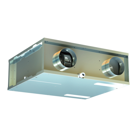
7. Condensation
•(The unit ay so eti es produce condensation which ust be
drained away. A 21.5/22 dia pipe outlet is provided on this unit).
Note: optional left or right hand drain connectors (21.5/22mm) are fit-
ted. A drainage pipe must be connected to the appropriate side, dependent
on the positions of the supply and extract ducting. Refer to figs A and B.
•
If the ducting is installed as shown in Fig A, the drain ust be connected to
the left-hand outlet. If the ducting is installed as shown in Fig. B, the drain
ust be connected to the right-hand outlet. The unused drain outlet ust
be capped off.
• The drainage pipe ust be installed with a continuous fall fro the cabinet
to the external household drainage point and a wet or dry trap ust be fitted to prevent return air penetration.
• If any part of the condensate drain pipe passes through an unheated space, it ust be insulated with the equiv-
alent of at least 25 of insulating aterial with a ther al conductivity of 0.04 W/ K.
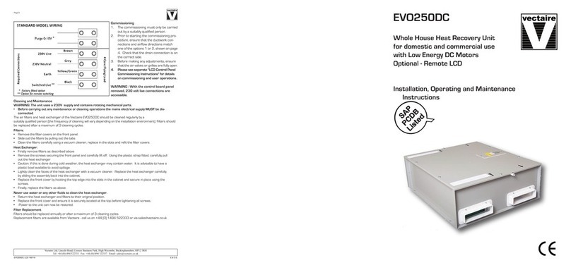
Electrical Connection
WARNING: these appliances must be earthed and all wiring must conform to current IEE Regulations and all ap-
plicable standards and Building Regulations.
• The unit is suitable for 230V, 50Hz Single phase supply.
• The unit is supplied with:
- A ains rated 4 core flexible cord (black, brown, grey and green/yellow) and 2 core 0-10v cables for purge
switching, or an external connector box.
Cables for any other external device will be provided and labelled on request
• A triple pole isolation switch with contact separation of at least 3 ust be used to connect the appliance to the
fixed wiring when using the Switched Live.
• Boost controls ust not be located within 1 etre of a cooker or where they ay be affected by excessive heat or
oisture.
• Boost and other external controls should be clearly identified and conveniently located.
• The boost facility can be activated by a switched live connection (in addition to the per anent supply live). The switched
live can be operated by a variety of external devices, including:
- PIRFF (passive infra red)*
- DRH240 (dyna ic re ote hu idistat)*
- THM (ther ostat)*
- a light switch (if ore than one light switch is used, each one must be a double pole switch)
- a re ote switch/pull cord
or via LCD control
(*PIRFF, DRH240 and THM ay have integral over-run ti er which controls the length of ti e that the fan will
continue to operate at its boost speed after the boost has been switched off.)
AB
