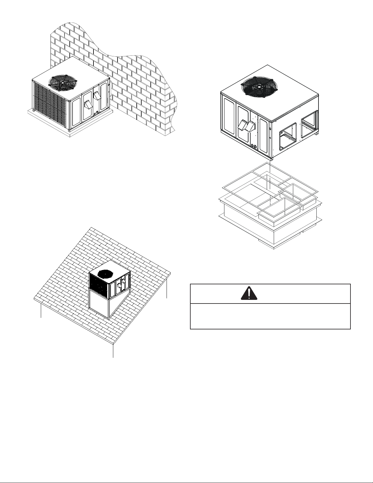
Amana A/GPU14 M Series User manual

©2020-2021 Goodman Manufacturing Company, L.P.
19001 Kermier Rd., Waller, TX 77484
www.goodmanmfg.com • www.amana-hac.com
is a registered trademark of Maytag Corporation or its related companies and is used under license. All rights reserved.
IOG-3021C
10/2021
A/GPU14 “M” SERIESWith R-410A
Single Package Gas-Electric Ultra-Low Nox Heating & Cooling Unit
Ax this manual and
Users Information Manual adjacent to the unit.
ATTENTION INSTALLING PERSONNEL:
Prior to installation, thoroughly familiarize yourself with this
Installation Manual. Observe all safety warnings. During
installation or repair, caution is to be observed.
It is your responsibility to install the product safely and to
educate the customer on its safe use.
RECOGNIZE THIS SYMBOL
AS A SAFETY PRECAUTION.
These installation instructions cover the outdoor installation
of self contained package air conditioners and heating
model for information regarding accessories.
*NOTE: Please contact your distributor or our website
manual.
This Forced Air Central Unit Design Complies With
Requirements Embodied In The American National
Standard / National Standard of Canada Shown Below.
ANSI Z21.47•CSA-2.3 Central Furnaces.
WARNING
WARNING

2
HIGH ALTITUDE....................................................................... 3
............................................................... 3
.............................. 3
REPLACEMENT PARTS ......................................................... 3
................................................................ 3
SAFETY INSTRUCTIONS ....................................................... 3
............................................................... 3
................................................... 4
GENERAL INFORMATION...................................................... 5
................................................. 6
UNIT LOCATION ...................................................................... 7
............................................................ 7
............................... 7
......................................... 8
..................................... 8
RIGGING DETAILS .................................................................. 8
GAS PIPING ............................................................................. 9
................................................................................. 9
........................................................... 10
ELECTRICAL WIRING ............................................................ 10
...................................................... 10
..................................................................... 11
CIRCULATING AIR AND FILTERS......................................... 11
....................................................... 11
.......................................................................... 11
............................................................................... 12
................................................................................... 12
................................ 12
................ 12
CONDENSATE DRAIN ............................................................ 12
..................................... 12
NORMAL SEQUENCES OF OPERATION............................. 13
............................................................................. 13
............................................................................. 13
........................................................................... 13
......................... 13
............................................................... 13
............................ 14
............................................................... 15
...................................................... 15
................................................ 16
.......................................... 16
................................. 16
.......................................... 16
...................................................................... 16
....................................................................... 17
................................................................ 17
................................ 17
........................................... 17
.. 17
................................................... 17
.............................................................. 17
SUPERHEAT ............................................................................ 18
TROUBLESHOOTING ............................................................. 18
..................................... 18
..................................................................... 18
................................................ 19
............................................................. 19
.................................................................... 19
..................... 19
............................................................ 19
......................................... 19
............................................................................... 20
.................................. 20
.......... 20
MAINTENANCE........................................................................ 20
................................ 20
.......................................... 20
.......... 20
.......................................... 20
................... 20
................... 20
. 20
............................................................................. 20
ACCESSORIES AND FUNCTIONAL PARTS........................ 21
............................................... 21
............................................................. 21
...................................................... 21
................................................................................ 22
............................................................ 22
............................................................... 23
................................................................ 24
....................................................... 26
............................................... 26
........................................... 27
................................... 29
.......................................................... 30
TABLE OF CONTENTS

3
Manifold pressure adjustments and ID plug change are
required for all installations above 4500 ft. The conversion
from “standard altitude” (as shipped from the factory) to
“high altitude” requires:
• Replacing ID plug
• Adjusting manifold pressure
Gas Input
Above
40,000 No Change HAUR40
60,000 No Change HAUR60
80,000 No Change HAUR80
To replace ID plug:
1. Turn OFF power to unit.
WARNING
2. Locate the PCB in the unit’s control section. Locate the
“ID Plug” on terminal labeled J9 on the PCB.
3. Remove the standard altitude ID plug by detaching it
from the PCB.
4. Install high altitude ID plug supplied in the high-altitude
kit. Verify that the ID plug is completely seated and
attached with the PCB or else the unit might not
function as intended.
Use the below manifold pressure settings:
Gas Input
Manifold
Pressure up
Manifold
Pressure at
Manifold
Pressure at
40,000 3.0” w.c. 2.7” w.c. 2.2” w.c
60,000 3.0” w.c 2.7” w.c. 2.2” w.c.
80,000 3.0” w.c. 2.7” w.c. 2.2” w.c.
REPLACEMENT PARTS
When reporting shortages or damages, or ordering repair
parts, give the complete unit model and serial numbers as
stamped on the unit’s nameplate.
Replacement parts for this appliance are available through
your contractor or local distributor. For the location of you
nearest distributor, see website www.goodmanmfg.com or
contact:
HOMEOWNER SUPPORT
GOODMAN MANUFACTURING COMPANY, L.P.
19001 KERMIER ROAD
WALLER, TEXAS 77484
855-770-5678
SAFETY INSTRUCTIONS
Before installing this unit, please read this manual to
adhered to, including maximum external static pressure to
unit, air temperature rise, minimum or maximum CFM and
motor speed connections.
Keep this literature in a safe place for future reference.

4
This unit has a Control System that compensates for
certain installation and environmental conditions. This unit
must:
• Be properly installed, operated, and maintained per the
instructions.
• Be serviced only by properly trained Service
Technicians.
This unit is not approved for use with gases other than
Natural Gas.
Units that are not installed, maintained, or operated
properly may result in “noisy” operation during the Heating
Cycle. If this unit is making unusual or objectionable noises
Adhere to the following warnings and cautions when
installing, adjusting, altering, servicing, or operating the
furnace. To ensure proper installation and operation,
installation and application of this product.
This furnace is manufactured for use with natural gas only.
in GAS PIPING section of this manual.
Always install a furnace to operate within the furnace’s
intended temperature-rise range with a duct system which
has external static pressure within the allowable range, as
WARNING
- WHAT TO DO IF YOU SMELL GAS:
•
•
•
WARNING
WARNING
WARNING
Failure to follow the safety warnings exactly could result in
or loss of life.
WARNING
la détection de fuites. Un incendie ou une explosion risque de

5
Carbon monoxide producing devices (such as an automobile, space
heater, gas water heater, etc.) should not be operated in enclosed areas
such as unvenlated garages, ulity rooms or parking areas because of
the danger of carbon monoxide (CO) poisoning resulng from the exhaust
emissions. If a furnace or air handler is installed in an enclosed area such
as a garage, ulity room or parking area and a carbon monoxide producing
device is operated therein, there must be adequate, direct outside
venlaon.
CARBON MONOXIDE POISONING HAZARD
Special Warning for In stallaon of Furnace or Air Handling Units in
Enclosed Areas su ch as Garages, Ulity Rooms or Parking Areas
This venlaon is necessary to avoid the danger of CO poisoning which
can occur if a carbon monoxide producing device connues to operate in
the enclosed area. Carbon monoxide emissions can be (re)circulated
throughout the structure if the furnace or air handler is operang in any
mode.
B10259-216
CO can cause serious illness including permanent brain
damage or death.
Los equipos ó aparatos que producen monóxido
(tal como automóvil, calentador de gas, calentador de
carbono (CO) que resulta de las
emisiones de gases de com busón.
gas, etc) no deben ser operados en áreas cerradas debido al riesgo
de envenenamiento por monóxido de
Si el equipo ó aparato se opera en
dichas áreas, debe exisr una adecuada venlación directa al exterior.
de carbono
agua por medio de
Advertencia especial para la instalación de calentadores ómanejadoras
de aire en áreas cerradas como estacionamientos ó cuartos de servicio.
B10259-216
RIESGO DE INTOXICACI ÓN PORMONÓXIDO DE CARBONO
El monóxido de carbono puede causar enfermedades severas
como daño cerebral permanente ó muerte.
Las emisiones de monóxido de carbono pueden circular a través
del aparato cuando se opera en cualquier modo.
Averssement special au sujet de l'installaon d'appareils de chauffage
ou de traitement d'air dans des endroits clos, tets les garages, les
locaux d'entreen et les staonnements.
B10259-216
RISQUE D'EMPOISONNEMENT AUMONOXYDE DE CARBONE
Evitez de mere en marche les appareils produisant du monoxyde
de carbone (tels que les automobile, les appareils de chauffage
autonome,etc.) dans des endroits non venlés tels que les
d'empoisonnement au monoxyde de carbone. Si vous devez faire
fonconner ces appareils dans un endroit clos, assures-vous
qu'il y ait une venlaon directe provenant de l'exterier.
Le monoxyde de
des
carbone peut causer des maladies graves telles que
dommages permanents au cerveau et meme la mort.
Les émissions de monoxyde de carbone peuvent etre recircules dans les
endroits clos, si l'appareil de chauffage ou de traitement d'air sont
en marche.
Cee venlaon est nécessaire pour éviter le danger d'intoxicaon
au CO pouvant survenir si un appareil produisant du monoxyde
de carbone connue de fonconner au sein de la zone confinée.
Esta venlaciónes necesaria para evitar el peligro de envenenamiento
por CO, que puede ocurrir si un monóxido
de carbono sigue operando en el lugar cerrado .
disposivo que produc e
WARNING
WARNING
WARNING
WARNING
GENERAL INFORMATION
WARNING
This unit is approved for outdoor installation ONLY.
Rated performance is achieved after 20 hours of operation.
www.goodmanmfg.com for Goodman® products. Within
the website, please select the residential or commercial
products menu and then select the submenu for the type
of product to be installed, such as air conditioners or heat
pumps, to access a list of product pages that each contain
must be installed, operated, and maintained in accordance
with these installation and operating instructions, all local
building codes and ordinances, or in their absence, with the
latest edition of the National Fuel Gas Code NFPA 54/ANSI
Z223.1 and National Standard of Canada CAN/CSA B149
Installation Codes.
The heating and cooling capacities of the unit should be
greater than or equal to the design heating and cooling
loads of the area to be conditioned. The loads should
be calculated by an approved method or in accordance
with A.S.H.R.A.E. Guide or Manual J - Load Calculations
published by the Air Conditioning Contractors of America.

6
Obtain from:
American National Standards Institute
25 West 43rd Street, 4th Floor
New York, NY 10036
Check the carton upon arrival for external damage. If
damage is found, a request for inspection by carrier agent
should be made in writing immediately.
Carefully inspect the unit for damage including damage
to the cabinetry. Any bolts or screws which may have
loosened in transit must be re-tightened. In the event of
damage, the receiver should:
1. Make notation on delivery receipt of any visible damage
to shipment or container.
2. Notify carrier promptly and request an inspection.
3.
as soon as possible-preferably within 5 days.
4. File the claim with the following supporting documents:
a.
bond.
b. Original paid freight bill or indemnity in lieu thereof.
c.
trade and other discounts or reductions.
d. Copy of the inspection report issued by carrier
representative at the time damage is reported to
the carrier. The carrier is responsible for making
prompt inspection of damage and for a thorough
investigation of each claim. The distributor or
manufacturer will not accept claims from dealers
for transportation damage.
WARNING

7
B149.1.
UNIT LOCATION
WARNING
•
proper condensate drainage, the unit must be mounted
level.
•
a building,and at least three feet above any forced
air inlet located within ten feet. The economizer/
manual fresh air intake/motorized fresh air intake
and combustion air inlet mounted on the unit are not
• To avoid possible corrosion of the heat exchanger,
do not locate the unit in an area where the outdoor
air (i.e. combustion air for the unit) will be frequently
contaminated by compounds containing chlorine or
swimming pool chemicals and chlorine bleaches, paint
stripper, adhesives, paints, varnishes, sealers, waxes
(which are not yet dried) and solvents used during
construction and remodeling. Various commercial and
industrial processes may also be sources of chlorine/
• To avoid possible illness or death of the building
occupants, do NOT locate outside air intake device
(economizer, manual fresh air intake, motorized fresh
air intake) too close to an exhaust outlet, gas vent
distances required, consult local codes.
•
protection, proper operation, and service access (see
appendix). These clearances must be permanently
maintained.
•
unit must never be obstructed. If used, do not allow
the economizer/manual fresh air damper/ motorized
fresh air damper to become blocked by snow or debris.
In some climates or locations, it may be necessary to
elevate the unit to avoid these problems.
• Damper must be in open position when appliance main
burner(s) is operating.
Le registre doit être ouvert lorsque tout brûleur principal
de l’appareil est en état de fonctionnement.
• When the unit is heating, the temperature of the return
air entering the unit must be between 50° F and 100° F.
• Units manufactured on or after May 1, 2017 are not
permitted to be used in Canada for heating of buildings
or structures under construction.
When the unit is installed on the ground adjacent to the
building, a level concrete (or equal) base is recommended.
Prepare a base that is 3” larger than the package unit
footprint and a minimum of 3” thick.
•
water from higher ground can collect in the unit.
• The top of the unit should be completely unobstructed.
If units are to be located under an overhang, there
should be a minimum of 48” clearance and provisions
overhang.

8
• To avoid possible property damage or personal injury,
the weight of the unit(s) and snow or water loads as
required by local codes. Consult a structural engineer
to determine the weight capabilities of the roof.
•
Class A, Class B, or Class C roof covering material.
•
service personnel should be provided.
•
locating and mounting the curb and package unit.
• Ductwork must be constructed using industry
guidelines. The duct work must be placed into the roof
curb before mounting the package unit.
•
RIGGING DETAILS
WARNING
Refer to the Roof Curb Installation Instructions for proper
curb installation. Curbing must be installed in compliance
Lower unit carefully onto roof mounting curb. While rigging
unit, center of gravity will cause condenser end to be lower
than supply air end.

9
GAS PIPING
The rating plate is stamped with the model number, type of
gas and gas input rating. Make sure the unit is equipped to
operate on the type of gas available.
Natural Min. 5.0" W.C., Ma x. 10.0" W.C.
INLET GAS PRESSURE
Inlet Gas Pressure Must be within the Minimum and the
Maximum Value Shown in the Inlet Gas Pressure Table.
The minimum supply pressure should not vary from that
shown in the table because this could prevent the unit
from having dependable ignition. In addition, gas input to
the burners must not exceed the rated input shown on the
heat exchanger failure.
CAUTION
WARNING
The rating plate is stamped with the model number, type of
gas and gas input rating. Make sure the unit is equipped
to operate on the type of gas available. The gas line
installation must comply with local codes, or in the absence
of local codes, with the latest edition of the National Fuel
Gas Code NFPA 54/ANSI Z223.1.
Natural Gas Connection
1/2 3/4 11 1/4 1 1 /2
10 132 278 520 1050 1600
20 92 190 350 730 1100
30 73 152 285 590 980
40 63 130 245 500 760
50 56 115 215 440 670
60 50 105 195 400 610
70 46 96 180 370 560
80 43 90 170 350 530
90 40 84 160 320 490
100 38 79 150 305 460
Pressure= .50 PSIG or less and Pressure Drop of 0.3" W.C.
(Based on 0.60 Specific Gravity Gas)
Natural Gas Capacity of Pipe
in Cubic Feet of Gas Per Hour (CFH)
Nominal Black Pipe Size (inches)
Length of
Pipe in Feet
Heating Value of Gas (BTU/Cubic Foot
CFH =
BTUH Furnace Input
1. Refer to the Proper Piping Practice drawing for the
general layout at the unit. The following rules apply:
2.
permitted as long as it is in agreement with local codes.
3. Use pipe joint compound on male threads only. Pipe
joint compound must be resistant to the action of the
fuel used.
4. Use ground joint unions.
5. Install a drip leg to trap dirt and moisture before it can
enter the gas valve. The drip leg must be a minimum
of three inches long.
6. Use two pipe wrenches when making connection to
the gas valve to keep it from turning.
7.
(within six feet of unit) between the meter and the unit.
8. Tighten all joints securely.
9. The unit must be connected to the building piping by
one of the following methods:
•
•
(Aluminum alloy tubing must not be used in
exterior locations)
• Listed gas appliance connectors used in
accordance with the terms of their listing that are
completely in the same room as the equipment.
• In the prior two methods above the connector
or tubing must be protected from physical and
thermal damage. Aluminum alloy tubing and
connectors must be coated to protect against
external corrosion when in contact with masonry,
plaster or insulation or are subject to repeated
wettings by liquids (water - not rain water,
detergents or sewage).

10
WARNING
•
•
•
WARNING
There will be air in the gas supply line after testing for leaks
on a new installation. Therefore, the air must be bled from
the line by loosening the ground joint union until pure gas
gas has been dissipated in the air. Be certain there is no
The unit is placed in operation by closing the main electrical
disconnect switch for the unit.
ELECTRICAL WIRING
has good air circulation.
Movement of air must not be obstructed by furniture, door,
draperies, etc. The thermostat must not be mounted where
television, etc. Consult the Instruction Sheet packaged with
thermostat for mounting instructions.
WARNING
The units are designed for operation on 60 hertz current
and at voltages as shown on the rating plate. All internal
wiring in the unit is complete. It is necessary to bring in the
power supply to the contactor as shown on the unit wiring
diagram which is supplied with each unit. The low voltage
wiring must be connected between the unit control panel
and the room thermostat.
R C G W Y
THERMOSTAT
RD BL GR WH YL YL
1 STAGE COOLING - 1 PHASE POWER
R C G
RD BL GR WH
W1 W2 Y1 Y2
YL YL
PUPU
THERMOSTAT
2 STAGE COOLING - 1 PHASE POWER
WIRING LEGEND
FACTORY WIRING
FIELD WIRING
WIRE NUT CONNECTION
Refer to the unit wiring diagram for electrical connections.
When installed, the unit must be electrically grounded in
accordance with local codes or in the absence of local
codes, with the National Electrical Code, ANSI/NFPA No.
70, and/or the CSA C22.1 Electrical Code. Ensure low
voltage connections are waterproof.
WARNING

11
CAUTION
CAUTION
For unit protection, use a fuse or hacr circuit breaker that
is in excess of the circuit ampacity, but less than or equal
to the maximum overcurrent protection device. DO NOT
EXCEED THE MAXIMUM OVERCURRENT DEVICE SIZE
SHOWN ON UNIT DATA PLATE.
All line voltage connections must be made through
wiring must be in approved weatherproof conduit. Low
voltage wiring from the unit control panel to the thermostat
requires coded cable. See below for ground level and
rooftop wiring.
Rated
208/230V 197 253
The unit transformer is factory connected for 230V
operation. If the unit is to operate on 208V, reconnect
the transformer primary lead as shown on the unit wiring
diagram. The induced draft blower on some models is
equipped with a low speed 230V lead (blue) and a low
speed 208V lead (black). If equipped, connect the induced
draft blower low speed 208V lead (black) in place of the low
speed 230V lead (blue). Place the unused 230V lead on
the “PARK” terminal located on ignition control.
BRANCH CIRCUIT
AMPACITY
15 20 25 30 35 40 45 50
SUPPLY WIRE
LENGTH - FEET
200 6 4 4 4 3 3 2 2
150 8 6 6 4 4 4 3 3
100 10 8 8 6 6 6 4 4
50 14 12 10 10 8 8 6 6
CIRCULATING AIR AND FILTERS
Units can easily be converted from horizontal to down-
installations, the installer should measure the total external
static and review the blower performance charts before
performing the installation. In some installations it will be
necessary to change the blower speed to provide proper air
Single phase models are shipped without horizontal duct
covers. If needed, these kits may be ordered through
Goodman’s Service Parts department.
Down Discharge Applications
Cut insulation around bottom openings and remove panels
from the bottom of the unit, saving the screws holding the
panels in place.
Duct systems and register sizes must be properly designed
for the C.F.M. and external static pressure rating of
the unit. Ductwork should be designed in accordance
with the recommended methods of Air Conditioning
Contractors of America Manual D (Residential) or Manual Q
(Commercial). All ductwork exposed to the outdoors must
include a weatherproof barrier and adequate insulation.
A duct system should be installed in accordance with
Standards of the National Board of Fire Underwriters for
the Installation of Air Conditioning, Warm Air Heating and
Ventilating Systems. Pamphlets No. 90A and 90B.

12
The supply duct from the unit through a wall may be
installed without clearance. However, minimum unit
clearances as shown in the appendix must be maintained.
The supply duct should be provided with an access panel
large enough to inspect the air chamber downstream of
the heat exchanger. A cover should be tightly attached to
prevent air leaks.
Dimension illustration in the appendix.
For down-discharge applications, the ductwork should
be attached to the roof curb prior to installing the unit.
Ductwork dimensions are shown in the roof curb installation
manual.
If desired, supply and return duct connections to the unit
unit operating sound transmission.
CAUTION
size information.
Filters installed external to the unit should be sized in
accordance with their manufacturer recommendations. A
of 300 feet per minute.
Filter Installation
1.
2.
3.
4. Using the three screws provided, attach the hood
opening in the utility panel.
SCREEN
HOOD
LOWER
FLUE
HOOD
LIP
1. Locate the second hood.
2. Using the three screws provided, attach the hood
(with the opening facing down) to the heat exchanger
access door.
CONDENSATE DRAIN
piping. An external trap must be installed for proper
condensate drainage.
DRAIN
CONNECTION
UNIT 2" MINIMUM
FLEXIBLE
TUBING-HOSE
OR PIPE
3" MINIMUM
A POSITIVE LIQUID
SEAL IS REQUIRED

13
NORMAL SEQUENCES OF OPERATION
This unit is equipped with an ignition control that
automatically lights the main burner. DO NOT attempt to
light the main burners by any other method.
1. R and W thermostat contacts close, initiating a call for
heat.
2. Integrated control module performs safety circuit
checks.
3. Inducer draft blower is energized for 30 second pre-
purge period causing pressure sensor contacts to
close.
4. At the end of pre-purge period, integrated control
setting.
5.
integrated control module, the spark igniter and gas
valve are energized for 4 seconds.
6.
detected.
7. The 5-second HEAT FAN ON delay time begins after
main burner lights.
8. The unit delivers heat to the conditioned space until
monitors safety circuits continuously.
9. R and W thermostat contacts open, completing the
10. Induced draft blower keeps operating for 30-second
post purge.
11. Ignition control begins timing the HEAT FAN OFF
delay. There is an adjustable HEAT FAN OFF delay of
approximately 90/120/150/180 seconds (factory set at
150).
1. Thermostat calls for low or high stage cooling.
2. If the thermostat call is for low stage cooling, the
compressor and outdoor fan are energized at low
stage. If the thermostat call is for high stage cooling,
the compressor and outdoor fan are energized at high
stage.
3. The indoor blower will energize approximately 6
seconds later.
4. The unit delivers cooling to the conditioned space until
5. The compressor and outdoor fan will be de-energized
when the thermostat opens.
6. The indoor blower continues to run at low cool speed
for approximately 60 seconds after the thermostat is
coil to be transferred to the conditioned space. Then,
the indoor blower is de-energized.
1. Thermostat calls for FAN ONLY by energizing “G”.
2. Indoor blower is energized at fan only speed.
3. The indoor blower is immediately de-energized once
thermostat call for FAN is removed.
This unit is equipped with an electronic ignition device to
automatically light the main burners. It also has a power
vent blower to exhaust combustion products.
On new installations, or if a major component has been
replaced, the operation of the unit must be checked.
Check unit operation as outlined in the following
instructions. If any sparking, odors, or unusual sounds are
errors, or obstructions in or near the blower motors. Duct
covers must be removed before operating unit.
The burner temperature switch is mounted on the burner
box assembly to monitor the burner box temperature. It is
normally closed (electrically), auto-reset sensor. An input
to the control is provided by the normally closed blocked
burner switch. An open blocked burner switch interrupts
current to the gas valve which closes the valve. This switch
into the heat exchanger.
The secondary limit control is located on the top of the
blower scroll assembly. This control opens when elevated
temperatures are sensed. Elevated temperatures at the
control are normally caused by blower failure. The reason
for the opening should be determined and repaired prior to
resetting.
If the power to the unit is interrupted during the heating
cycle, it may cause the secondary limit to trip. Once the
blower compartment temperature drops below the limit
reset temperature, the limit will automatically reset.

14
Secondary
Control Limit
Back of Unit
Pre-Operation Checks
1. Close the manual gas valve external to the unit.
2.
3. Set the room thermostat to its lowest possible setting.
4. Remove the heat exchanger door on the side of the
unit by removing screws.
5. This unit is equipped with an ignition device which
automatically lights the main burner. DO NOT try to
light burner by any other method.
6. Move the gas control valve switch to the OFF position.
Do not force.
7.
8. Smell for gas, including near the ground. This is
important because some types of gas are heavier
smell gas, immediately follow the warnings near the
minutes and no gas smell is noted, move the gas
control valve switch to the ON position.
9. Replace the heat exchanger door on the side of the
unit.
10. Open the manual gas valve external to the unit.
11. Turn on the electrical power supply to the unit.
12. Set the thermostat to desired setting.
Gas Supply And Manifold Check
Gas supply pressure and manifold pressure with the
CAUTION
The line pressure supplied to the gas valve must be within
pressure can be measured at the gas valve inlet pressure
The supply pressure must be measured with the unit OFF.
To measure inlet pressure, use the following procedure.
1.
valve external to the furnace.
2. Turn OFF all electrical power to the system.
3. Inlet pressure tap connections:
a. White-Rodgers Valve:
Back inlet pressure test screw (inlet pressure tap
out one turn (counterclockwise, not more than one
turn).
2. Connect manometer (or appropriate pressure gauge)
at either the gas valve inlet pressure tap or the gas
piping drip leg. See White-Rodgers 36J22Y-204 gas
valve for location of inlet pressure tap.
3. Turn ON the gas supply.
4. Turn On power and operate the furnace and all other
gas consuming appliances on the same gas supply
line.
5. Using a leak detection solution or soap suds, check for
leaks at screw (White-Rodgers valve). Bubbles forming
indicate a leak. SHUT OFF GAS AND REPAIR ALL
LEAKS IMMEDIATELY!
6.
Adjust supply pressure using the Inlet Gas Supply
Pressure table shown below. If supply pressure
adjustments to pressure regulator, gas piping size,
etc., and/or consult with local gas utility.
Natural Gas Min. 5.0" W.C., Max. 10.0" W.C.
INLET GAS SUPPLY PRESSURE
7. Turn OFF all electrical power and gas supply to the
system.

15
8. Remove the manometer hose from the hose barb
9. Replace inlet pressure tap:
a. White-Rodgers Valve:
Turn inlet pressure test screw in to seal pressure
port (clockwise, 7 in-lb minimum).
10. Retest for leaks. If bubbles form, shut down gas and
repair leaks immediately.
11. If there are no leaks, turn ON electrical power and gas
supply to the system.
12. Turn valve switch ON.
.
CAUTION
Only small variations in gas pressure should be made by
adjusting the gas valve pressure regulator. The manifold
pressure must be measured with the burners operating.
To measure and adjust the manifold pressure, use the
following procedure.
1.
valve external to the furnace.
2. Turn OFF all electrical power to the system.
3. Outlet pressure tap connections:
a. White-Rodgers Valve:
Back outlet pressure test screw (outlet pressure
Tap) out one turn (counterclockwise, not more than
one turn).
4. Connect manometer (or appropriate pressure gauge)
at the gas valve outlet pressure tap. See White-
Rodgers 36J22Y-204 gas valve for location of outlet
pressure tap.
5. Turn ON the gas supply.
6. Turn ON power and close thermostat “R” and “W”
contacts to provide a call for heat.
7. Using a leak detection solution or soap suds, check
for leaks at outlet pressure tap screw (White-Rodgers
valve). Bubbles forming indicate a leak. SHUT OFF
GAS AND REPAIR ALL LEAKS IMMEDIATELY!
8.
Adjust manifold pressure using the following Manifold
Gas Pressure table.
Natural Gas 2.8" - 3.2" w.c.
Manifold Gas Pressure
The Manifold Gas Pressure must be within the range
9. Remove regulator cover screw from the outlet
pressure regulator and turn screw clockwise to
increase pressure or counterclockwise to decrease
pressure. Replace regulator cover screw.
10. Turn OFF all electrical power and gas supply to the
system.
11. Remove the manometer hose from the hose barb
12. Replace outlet pressure tap:
a. White-Rodgers Valve: Turn outlet pressure test
screw in to seal pressure port (clockwise, 7 in-lb
minimum).
14. Turn ON electrical power and gas supply to the
system.
15. Close thermostat contacts to provide a call for heat.
16. Retest for leaks. If bubbles form, SHUT OFF GAS
AND REPAIR ALL LEAKS IMMEDIATELY!
To measure the gas input use a gas meter and proceed as
follows:
1.
unit.
2. With the unit operating, time the smallest dial on the
meter for one complete revolution. If this is a 2 cubic
dial, use the seconds as is. This gives the seconds per
cubic foot of gas being delivered to the unit.
3. INPUT=GAS HTG VALUE x 3600 / SEC. PER CUBIC
FOOT
Natural gas with a heating value of 1000
BTU per cubic foot and 36 seconds per cubic foot as
determined by
Step 2, then:
Input = 1000 x 3600 / 36 = 100,000 BTU per Hour.

16
4.
sure all pilot burners are operating.
Check the temperature rise through the unit by placing
thermometers in supply and return air registers as close
to the unit as possible. Thermometers must not be able to
sample temperature directly from the unit heat exchangers,
or false readings could be obtained.
1.
unit operated for 15 minutes before taking readings.
2. The temperature rise must be within the range
With a properly designed system, the proper amount of
temperature rise will normally be obtained when the unit
is operated at rated input with the recommended blower
speed.
If the correct amount of temperature rise is not obtained,
it may be necessary to change the blower speed. A higher
blower speed will lower the temperature rise. A slower
blower speed will increase the temperature rise.
The total external static pressure must be checked on this
1. Using a digital manometer measure the static pressure
of the return duct at the inlet of the unit (Negative
Pressure).
2. Measure the static pressure of the supply duct (Positive
Pressure).
3. Add the two readings together.
4. Consult proper table for quantity of air.
If the external static pressure exceeds the minimum or
maximum allowable statics, check for closed dampers, dirty
WARNING
A/GPU14 models are equipped with EEM motors. EEM
motors are constant torque motors with very low power
consumption. This motor is energized by 24V. Adjust the
CFM for the unit by changing the 24V low voltage leads to
the speed terminal block on the motor.
SPEED
TAP
DEFINITION
LEAD
COLOR
SPEED
TAP
DEFINITION
LEAD
COLOR
SPEED
TAP
DEFINITION
LEAD
COLOR
T1 Fan Only Green T2 High Speed T4 Low Speed Yellow
T3 Low Speed White T5 High Speed
FAN ONLY
HEATING
COOLING

17
SPEED
TAP
DEFINITION
LEAD
COLOR
SPEED
TAP
DEFINITION
LEAD
COLOR
SPEED
TAP
DEFINITION
LEAD
COLOR
T1 Fan Only Green T2 Heat White T3 Low Speed Purple
T4 High Speed Yellow
T5
High Speed
Hi-Static
FAN ONLY
HEATING
COOLING
Check limit control operation after 15 minutes of operation
by blocking the return air grille(s).
1. After several minutes the main burners must go OFF.
Blower will continue to run.
2. Remove air restrictions and main burners will relight
after a cool down period of a few minutes.
Adjust the thermostat setting below room temperature.
1. Main burners must go OFF.
2. Circulating Air Blower will continue to run for 90, 120,
150 or 180 seconds, depending on the setting.
WARNING
1. Set the thermostat to lowest setting.
2.
3. Remove the heat exchanger door on the side of the
unit by removing screws.
4. Move the gas control valve switch to the OFF position.
Do not force.
5.
6. Replace the heat exchanger door on the unit.
7. If cooling and/or air circulation will be desired, turn
ON the electrical power.
The compressor includes components which are designed
to protect the compressor against abnormal operating
conditions.
WARNING
WARNING
the unit’s refrigerant charge must be checked. The unit
comes factory charged, but this charge is based on 325
CFM per ton and minimum ESP per AHRI test conditions
(generally between .15-.28 ESP). When air quantity or
the compressor suction line.
After superheat is adjusted it is recommended to check unit
sub-cooling at the condenser coil liquid line out. For charge
adjustments, see superheat and sub-cooling charts show
for each model.
Check unit charge before putting the cooling section into
full operation. The unit has a thermostatic expansion valve
metering device. To ensure the unit is properly charged
for the intended application, check the unit refrigerant
sub-cooling at the condenser. The refrigerant sub-
cooling is a function of outdoor ambient temperature and
return air temperature of the conditioned space. It is the
installing contractors responsibility to ensure the proper
refrigerant sub-cooling at the condenser is adjusted for
each application. As the outdoor ambient temperature rises
the sub-cooling decreases and as the outdoor ambient
temperature lowers, the sub-cooling increases.
To adjust superheat, remove the control box cover
and locate the expansion valve on the liquid line of the
evaporator. Unscrew the cover from the expansion valve,
locate the adjustment screw, and turn it clockwise (in) to

18
increase superheat or counterclockwise (out) to decrease
superheat. Replace adjustment cap. Wait a minimum of 10
minutes between adjustments to allow time for the TXV and
pressures to stabilize.
SUPERHEAT
Checking Superheat
Refrigerant gas is considered superheated whenever its
temperature is higher than the saturation temperature
corresponding to its pressure. The degree of superheat
equals the degrees of temperature increase above
the saturation temperature at existing pressure. See
Temperature - Pressure Chart.
1. Run system at least 10 minutes to allow pressure to
stabilize.
2. Temporarily install thermometer on suction (large) line
near compressor with adequate contact and insulate
for best possible reading.
3. Refer to the superheat table provided for proper system
superheat. Add charge to lower superheat or recover
charge to raise superheat.
65 70 75 80 85
100 ---10 10
95 - - 10 10 10
90 - - 12 15 18
85 -10 13 17 20
80 -10 15 21 26
75 10 13 17 25 29
70 10 17 20 28 32
65 13 19 26 32 35
60 17 25 30 33 37
Ambient Condenser Inlet
Temp (°F Drybulb)
Return Air Temp. (°F Drybulb)
a. Suction Pressure = 143
b. Corresponding Temp. °F. = 50
c. Thermometer on Suction Line = 59°F.
To obtain the degrees temperature of superheat, subtract
50.0 from 59.0°F.
in the ± range of allowable superheat.
Checking Subcooling
Refrigerant liquid is considered subcooled when its
temperature is lower than the saturation temperature
corresponding to its pressure. The degree of subcooling
equals the degrees of temperature decrease below the
saturation temperature at the existing pressure.
1. Attach an accurate thermometer or preferably a
thermocouple type temperature tester to the liquid line
close to the pressure switch.
2. Install a high side pressure gauge on the liquid access
3. Record the gauge pressure and the temperature of the
line.
4. Compare the hi-pressure reading to the “Required
Liquid Line Temperature” chart. Find the hi-pressure
value on the left column. Follow that line right to the
column under the design subcooling value. Where the
two intersect is the required liquid line temperature.
Alternately you can convert the liquid line pressure
reading in Temperature - Pressure Chart and reading to
5.
pressure to temperature conversion is the amount of
subcooling.
a. Liquid Line Pressure = 417
b. Corresponding Temp. °F. = 120°
c. Thermometer on Liquid line = 109°F.
To obtain the amount of subcooling, subtract 109°F
design subcooling range for your unit.
See R410A Pressure vs. Temperature chart.
Cooling Operation
1. Turn on the electrical power supply to the unit.
2. Place the room thermostat selector switch in the
COOL position (or AUTO if available, and if automatic
changeover from cooling to heating is desired).
3. Set the room thermostat to the desired temperature.
TROUBLESHOOTING
The following presents probable causes of questionable
unit operation. Refer to Diagnostic Indicator Chart for
an interpretation of the signal and to this section for an
explanation.
Remove the control box access panel and note the number
Chart for an interpretation of the signal and to this section
for an explanation.
The ignition control is equipped with a momentary push-
button switch that can be used to display on the diagnostic
control is powered, the fault code history can be retrieved

19
for display by depressing and releasing the button once
History (up to 5 fault codes from newest to oldest). The
Fault Code History is retained between power cycles until
cleared. A fault code is added to the history log as it is
item. If the history log is already full, then the oldest entry is
dropped from the log and the remaining entries are moved
down in the Fault Code History so that the new fault can be
added to the Fault Code History as the most recent fault.
An external lockout occurs if the integrated ignition control
determines that a measurable combustion cannot be
established within three (3) consecutive ignition attempts.
ignition, the gas valve is de-energized, 30 second inter-
purge cycle is completed, and ignition is re-attempted. The
control will repeat this routine three times if a measurable
the induced draft blower and go into a lockout state.
the circulator blower at the heat speed and then begin a
subsequent attempts, the control will recycle the ignition
sequence.
to failed ignition attempts. The integrated control will
automatically reset after one hour, or it can be reset by
removing the thermostat signal or disconnecting the
The pressure sensor is mounted near induced draft blower.
Its function is to regulate the induced draft blower’s speed
in order to maintain proper air-fuel ratio for clean and
reliable combustion. The electrical output signal from the
sensor is expected to be proportional to the magnitude of
pressure and the ambient air pressure. The pressure
At the beginning of a call for heat, the control ensures the
sensor output is outside the acceptable range for the null
lockout timer has expired, the control resumes normal
operation.
During inducer operation, including all operating modes
except for the null test, the control monitors the pressure
sensor output for expected values. The control limits
during normal operation are expected to be within certain
tolerances of the target pressures. In response to a
lockout. After the lockout timer has expired, the control
resumes normal operation.
A primary limit will open due to excessive supply air
motor speed tap (see wiring diagram), and limit. This limit
will automatically reset once the temperature falls below a
preset level.
If a limit switch opens, the gas valve is immediately de-
energized, the induced draft and air circulating blowers
are energized. The induced draft and air circulator blowers
remain energized for 5 minutes or until the limit switch re-
combustion and air circulator blowers are energized. The
control can be reset by removing the power supply to the
unit or it will automatically reset after one hour. Miswiring is
the probable cause for this fault. The initial lockout period is
5 minutes. After that time, the control continues to monitor
Under some conditions, the fuel or air supply can create a
amber diagnostic LED. The unit will continue to operate
The burner temperature switch is mounted on the burner
box assembly to monitor the burner box temperature. It is
normally closed (electrically), auto-reset switch. This switch
into the heat exchanger.
The control senses an open blocked burner switch,
indicating that the burner temperature/pressure has
exceeded its set point. The control de-energizes the gas
valve, energizes the inducer to the pre-purge setting and

20
minutes. After this time elapses, the control evaluates the
state of the blocked burner switch. If the switch is closed,
the control resumes normal operation. The control will enter
a one hour lockout state if the blocked burner switch fails to
reset before the recovery timer has expired.
The control operational parameters are stored in ID Plug
which connects on the circuit board. The control requires a
valid ID plug present to operate in heating mode. If a valid
ID plug is not present the control will not respond to a call
for heat. However, the control will respond to thermostat
inputs “Y” or “G”, operating the appropriate fan output.
The cooling delays are ignored in this operating mode.
The control puts the burner into hard lockout and will not
respond to heating requests until the power is cycled with a
valid ID plug installed.
In the event of intermittent power losses or intermittent
thermostat operation, the control system will delay output
to the compressor contactor for three minutes from the time
power is restored or thermostat call for cooling is restored.
Some models include a high pressure cutout switch and/
or a low pressure switch. The high pressure cutout switch
protects the refrigeration system from excessive operating
pressures. The low pressure switch protects the refriger-
ation system from very low operating pressures due to a
loss of refrigerant. Compressor operation will be disabled if
either of these devices opens.
MAINTENANCE
WARNING
Have the gas heating section of the unit checked at least
once a year before the heating season begins, to be sure
not blocked by debris, which would prevent adequate
combustion air and a properly operating vent system.
heating or cooling performance. Filter inspection should be
because of local conditions and usage.
washed with water, thoroughly dried and sprayed with a
should last several years. However, should one become
torn or uncleanable, it should be replaced.
important in installations with extended periods of direct
sunlight.
inspected annually and cleaned as frequently as necessary
Bearings on the air circulating blower motor, condenser
motor and the combustion fan motor are permanently
lubricated. No additional oiling is required.
by the fuel or combustion air supply, can be removed by
At the start of each heating season, inspect and, if
1.
2. Remove burner assembly by disconnecting the gas
line and removing the manifold bracket from the
partition panel.
3.
collector box cover from the partition panel.
Table of contents
Other Amana Heating System manuals
Popular Heating System manuals by other brands

Vent-Axia
Vent-Axia Sentinel Kinetic 200ZH Installation & commissioning

BoilerMag
BoilerMag BM22 Installation & servicing instructions

Aqua-Hot
Aqua-Hot 200 Series Use and care guide

Pichler
Pichler LG 250 A Operating and installation instructions

Rheem
Rheem RHWB series instruction manual

Valeo
Valeo spheros thermo 230 Workshop manual

Toyostove
Toyostove Laser 73 Installation and operation instructions

System air
System air VTR 100/B LITE user manual

Toyotomi
Toyotomi Laser 60AT Installation & operation instructions

Fenix
Fenix PFP 1 user manual

Carrier
Carrier 40VMH024 Installation and maintenance instructions

Viessmann
Viessmann VITOCELL 300B Service instructions for contractors