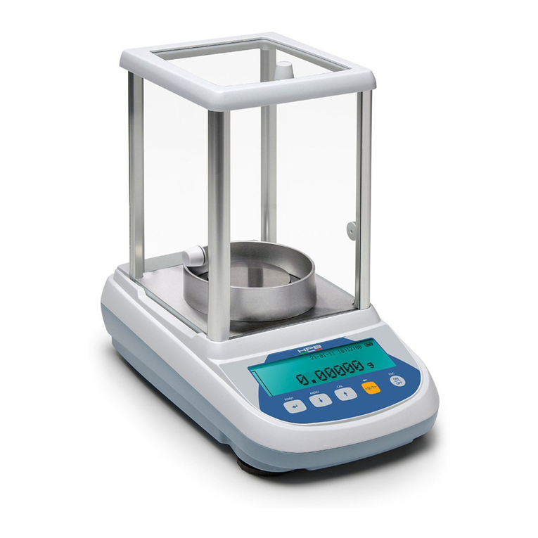
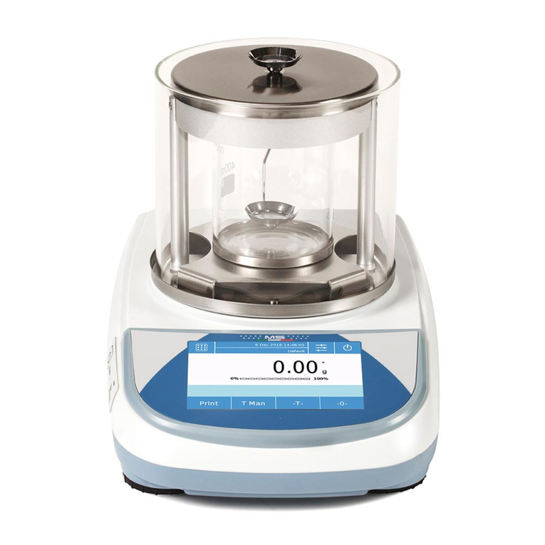
BEL Engineering Mark L User manual

Man_B_M_MW_L_LW_EN_th_RL_6.xx_RL_3.xx_Rev1 12/2/15
User Manual
Revision software Mark L / LW:
RL_6.xx and RL_3.xx
or higher
Revision software Mark M / MW:
R_6.xx and R_3.xx
or higher

1
INDEX
1
INSTALLATION INSTRUCTION........................................................................................3
2
STORAGE .................................................................................................................................4
3
WEIGHING PAN ASSEMBLY..............................................................................................5
4
KEYBOARD AND DISPLAY.................................................................................................6
5
OVERVIEW..............................................................................................................................7
5.1
F
RONT PART OF THE BALANCE
,
M
/
MW
/
L
/
LW
MODELS
................................................. 7
5.2
R
EAR AND BOTTOM PART OF THE BALANCE
,
M
/
MW
/
L
/
LW
MODELS
............................ 8
5.3
R
EAR AND BOTTOM PART OF THE BALANCE
,
M
/
MW
/
L
/
LW
MODELS
V
ERSION
S
QUARE
P
AN
9
6
WEIGHING.............................................................................................................................10
6.1
S
TAND
B
Y
..........................................................................................................................10
6.2
S
IMPLE WEIGHING
..............................................................................................................10
7
CALIBRATION......................................................................................................................11
7.1
E
XTERNAL CALIBRATION
...................................................................................................11
7.2
I
NTERNAL CALIBRATION
....................................................................................................13
7.2.1
Autocalibration (AUT-CAL).........................................................................................13
7.2.2
Internal calibration (I-CAL) [locked for verified balances].......................................14
7.2.3
External calibration (E-CAL) [locked for verified balances].....................................14
7.2.4
Technical calibration (TEC-CAL) [locked for verified balances]..............................15
7.3
V
ERIFICATION
.................................................................................................................... 16
8
TARE FUNCTION.................................................................................................................17
8.1
M
ANUAL TARE FUNCTION
..................................................................................................18
8.2
O
PTIONAL ALPHANUMERIC EXTERNAL KEYBOARD
...........................................................19
9
WEIGHT UNITS ....................................................................................................................21
10
PC COMMUNICATION SETTING....................................................................................23
11
PRINTER SERIAL COMMUNICATION SELECTION.................................................24
12
TRANSMISSION SPEED SELECTION ............................................................................25
13
AUTOZERO FUNCTION.....................................................................................................26
14
FILTERS SELECTION.........................................................................................................27
15
STABILITY FUNCTION......................................................................................................28
16
DISPLAY CONTRAST REGULATION.............................................................................29
17
DISPLAY BACKLIGHT SETUP.........................................................................................30
18
AUTO POWER-OFF FUNCTION.......................................................................................31
19
SELECTION OF WORKING MODE WITH TABLET..................................................32
20
PIECECOUNTING FUNCTION .........................................................................................34
20.1
V
ISUALIZATION OF TOTAL AND UNIT WEIGHT OF PIECES
...................................................35
20.2
M
ANUAL INSERTION OF THE UNIT AVERAGE WEIGHT
........................................................36

2
20.3
A
UTOMATIC UPDATE OF UNIT WEIGHT
.............................................................................. 37
21
DENSITY DETERMINATION OF A SOLID OR A LIQUID ........................................38
21.1
D
ENSITY DETERMINATION OF A SOLID
...............................................................................38
21.2
D
ENSITY DETERMINATION OF A LIQUID
.............................................................................40
22
MAXIMUM LOAD DETERMINATION FUNCTION ....................................................42
23
PERCENTAGE WEIGHING FUNCTION ........................................................................43
23.1
M
ODE WITH WEIGHT REFERENCE
.......................................................................................43
23.2
M
ODE WITH MANUAL INSERTION OF THE REFERENCE WEIGHT
..........................................44
24
ANIMAL WEIGHING FUNCTION....................................................................................46
25
TOTALIZING.........................................................................................................................47
26
THRESHOLD FUNCTION...................................................................................................49
26.1
B
OTH THRESHOLDS SET
.....................................................................................................50
26.2
L
OWER THRESHOLD SET ONLY
...........................................................................................50
26.3
H
IGHER THRESHOLD SET ONLY
..........................................................................................50
27
RS232 INTERFACE FEATURES........................................................................................51
28
ERROR CODES .....................................................................................................................57
29
MAINTENANCE AND CARE .............................................................................................58
30
QUICK GUIDE TO BALANCE PARAMETERS SETUP...............................................59
31
QUICK GUIDE TO THE USE OF THE BALANCE PROGRAMS...............................60
32 BALANCES SERIES M / MW / L / LW................................................................................61
33 WARRANTY..............................................................................................................................62
34 EQUIPMENT DISPOSAL........................................................................................................62

3
1 Installation instruction
WARNING:
Please follow carefully these steps for installing and use the new balance
before starting your work routine. A way of use of the instrument different
from this user manual will not guarantee the instrument’s safety anymore.
Remove the balance, calibration weight( if included) and accessories from the
cartoon and check for any visible damage of the instrument.
Do not install the balance in a place with air flows, heavy thermal changes and
vibrations.
Do not use the balance in blast risk environment.
The humidity rate of the balance environment must be between 45% and 75%
Place the weighing pan and the support pan on the balance (see par. 3).
Level the balance using the level bubble and levelling feet located underneath the
case
Connect power supply to connector 2 located on the rear panel of the unit (see
par. 5).
ATTENTION
In models with internal calibration remove the screw in the left lower
part of the balance (see par.5)

4
Insert power unit into AC outlet, which shall be easily accessible; after few
seconds the balance will automatically switch on.
Balance Warm-up:
Wait 8 hours from switch one for Analytical balanaces (0,0001g)
Wait 30 minutes for other models
Then calibrate the balance using the appropriate mass (if supplied), following
instructions (par.7).
It is strongly suggested not to disconnect the balance from the electrical
mains and to use the ON/OFF button to stand-by the balance when you
finished using it
Calibrate again the balance every time it’s moved to another place
Check balance calibration periodically.
We recommend not dropping heavy objects on balance pan, in order to avoid
damages.
Assistance service must be effected by specialized staff and the spare parts used
must be original. Therefore, it is necessary to apply to the reseller who sold the
equipment.
2 Storage
.
Storage temperature: +5 °C…+40°C
Storage humidity 45% - 75%.
Keep package in the case the balance should be sent back to the factory for service.
Disconnect the cables and the accessories for avoiding damages during
transportation.
Do not place the balance in extreme temperature and humidity condition and avoid
the balance to take strong hit.

5
3 Weighing pan assembly

6
4 Keyboard and display
*
Stability indicator
O
Zero indicator
%
Percentage weighing
PC
Piece counting
Battery charge indicator
Insert data mode
H
Upper threshold
L
Lower threshold
DS
Density measure mode
ct,
Measure unit
ozt, lb, GN, dwt, Kg, mg
Standby (OFF/ON) or escape
ESC.
TARE or zero button.
Selection CONFIRM or SEND
data to printer.
Balance setup MENU button.
Balance CALIBRATION button.
ESC
ESC

7
5 Overview
5.1
Front part of the balance, M / MW / L / LW models
1
2
3
4
5
6
Fig.1
Balance with circular and three-panes windshield
Name and function
1
Cap of windshield
2
Levelling bubble
3
Windshield
4
LCD display
5
Function buttons
6
Levelling feet

8
5.2
Rear and bottom part of the balance, M / MW / L / LW models
Fig.2
Rear and bottom part of the balance
Name and function (Fig.2)
1
Weighing pan
2
9 poles (pin) female connector for RS232 interface for printer/PC/external keyboard
3
Levelling feet
4
connector for power supply
5 Screws for balance closing. In models with 4 feet it is necessary first to remove the
two rear feet (one fixed and one moving) to access to the closing screws
6 Hook for under-balance weighing. Hook not available in internal calibration models
and for verified balances. Note: please remove the cap to access the hook
7 Protection screw for autocalibration motor (only for models with internal calibration).
ATTENTION: remove this screw by hand as soon as the balance is removed from
its package
2
3
3
1
4
5
5
6
5
7

9
5.3
Rear and bottom part of the balance, M / MW / L / LW models
Version Square Pan
Fig.3
Rear and bottom part of the balance
Name and function (Fig.3)
1
Weighing pan
2
9 poles (pin) female connector for RS232 interface for printer/PC/external keyboard
3
Levelling feet
4
connector for power supply
5 Screws for balance closing. In models with 4 feet it is necessary first to remove the
two rear feet (one fixed and one moving) to access to the closing screws
6 Hook for under-balance weighing. Hook not available in internal calibration models
and for verified balances. Note: please remove the cap to access the hook
7 Protection screw for autocalibration motor (only for models with internal calibration).
ATTENTION: remove this screw by hand as soon as the balance is removed from
its package
8
Adjustable rear
9 Fixed rear feet
2
3
3
1
4
8
5
6
6
5
5
7
9

10
6 Weighing
For verified Balances models at switch on it will appear “WARM UP” on
display and countdown will start
After having connected the balance to AC outlet, it will perform an internal circuits test,
after that the balance will set itself in stand-by mode.
6.1
Stand By
From “STAND BY” mode:
Press ON/OFF button to bring balance to work conditions.
Press again ON/OFF button to return to “STAND BY” condition.
6.2
Simple weighing
Load the sample to weigh on the pan and read the value on display as soon as the
stability symbol ж(star) appears
The digit that represents the verification division “e” is rounded with a frame

11
7 Calibration
Electronic balances take mass measurements making use of gravity (g). Difference of
latitude in geographic areas and altitude will vary gravity acceleration value (g).
Therefore, for accurate measurements, the balance must be adjusted to the local
environment. This adjustment is accomplished by calibration function.
7.1
External calibration
For verified Balances models the External calibration function is locked
Calibration is accomplished by pressing CAL button.
1. Press CAL button when pan is empty, dashes are displayed on the display.
2. When calibration weight value starts to flash, load the weight on the pan.
3. The display will stop flashing, indicating calibration weight value.
Once the calibration is effected will be shown the value of the calibrated weight and
the current unit of measure.
4. Unload calibration weight from the pan.
The balance is ready for weighing operations.
NOTE: if there is interference during calibration process, an error message will be displayed.

12
Moreover, it is possible to calibrate the balance with a calibration weight higher than the
one set by default:
1. Press and keep CAL button pressed with empty pan until the acoustic alarm
stops, then release the button. On display it will be visualized the string "-CAL-",
followed by flashing string "LOAD".
2. Load on the pan a weight equal higher or lower than default calibration weight; the
balance will recognize it as valid weight if equal or higher than calibration weight
as long as it is a whole number in comparison with the most meaningful digit of
calibration weight .
e.g.: if calibration weight is 200g, it will be possible to calibrate the balance with
values from 100g 200g, 300g, 400g up to the highest limit of balance weighing
range.
The message “LOAD” on display will stop flashing. Once calibration has been
effected, the value of calibrated weight will be displayed.
3. Unload calibration weight. The balance is ready for weighing operations.
NOTE: if there is interference during calibration process, an error message will be displayed.
2 Sec

13
7.2
Internal calibration
* only for models with internal calibration “-i”
In these balance models there are 4 calibration modes:
From display zero condition, press and keep pressed the MENU button until the acoustic
alarm gets mute, then release the button. The message “unitS” will be visualized on
display, press then MENU button until you visualize “Calib” on display. Press PRINT to
confirm.
1. Select the calibration mode you wish by pressing MENU button in sequence:
AUT-CAL: auto calibration
I-CAL: internal calibration
*
E-CAL: external calibration
*
TEC-CAL: technical calibration
*
2. Press PRINT button to confirm “AUT-CAL”, “I-CAL”, “E-CAL”.
To confirm “TEC-CAL” keep pressed the PRINT button until the acoustic alarm gets
mute.
3. After selection, the balance returns to calibration menu. Press and keep pressed
MENU button until the acoustic alarm gets mute, then release the button. Balance is
again ready for weighing operations.
7.2.1 Autocalibration (AUT-CAL)
This is Factory setting for verified balances models
The balance self-calibrates when the temperature variation exceeds the factory preset
value and at factory preset time intervals, through the internal reference mass, and only if
the balance pan is empty.
When the balance needs to perform the Automatic calibration, the display will show the
following message:
A 25-seconds countdown will start during which you can decide if:
*Locked for verified balances models

14
•Stop the automatic-calibration procedure by pressing the “ON/OFF button that will
be delayed of 5 minutes
or
•Let the countdown finish so that the automatic calibration starts
Note: during the countdown do NOT load nothing on the plate!
In this mode, it is also possible to carry out the calibration with the internal reference
mass by pressing the CAL button at any moment, first ensuring that no weight is loaded
on the plate.
1. Press CAL button with empty pan.
The message “CAL” will be displayed and balance calibration will be effected
automatically.
2. At the end of calibration, balance returns to normal weighing conditions.
If calibration is not finished due to vibrations or air flows, then the message “CAL
bUt” is displayed. Press again CAL button. If the problem repeats then select external
calibration and contact the product supplier.
7.2.2 Internal calibration (I-CAL) [locked for verified balances]
The balance calibrates itself with internal reference mass ONLY on user command by
pressing CAL button.
Before effecting internal calibration, be sure that there’s no weight loaded on the balance
pan.
7.2.3 External calibration (E-CAL) [locked for verified balances]
The balance is calibrated through an external reference mass (NOT provided with
models with internal calibration).
(Follow procedures described at paragraph 7.1)

15
7.2.4 Technical calibration (TEC-CAL) [locked for verified balances]
This function allows storing the value of internal reference mass whenever checking or
assistance actions require it.
1. After having selected the TEC-CAL calibration mode, press CAL button at empty
pan. It will be displayed “CAL”.
2. When the value of
calibration weight start flashing on display, load the weight on to the balance pan.
3. Wait the acoustic alarm and that the displayed calibrated weight value stops flashing,
then unload the weight from balance pan.
4. When string “0.000” is displayed continuously, then press and keep pressed the
PRINT button. This starts the internal weight value automatic acquisition and store.
During the acquisition cycle, the display will show “TEC-MEM”.
5. After having stored the value of internal calibration weight, balance returns to normal
weighing conditions.
6. Return to calibration menu as described at paragraph 6.2 and set the desired
calibration mode: internal, automatic or external..
ATTENTION : this procedure must be effected only using E2-class reference
masses.

16
7.3
Verification
General introduction:
According to EU directive 90/384/EEC balances must be verified if they are used for
legally controlled area as follows:
a) For commercial transactions if the price of goods is determined by weighing.
b) For the production of medicines in pharmacies as well as for analyses in the
medical and pharmaceutical laboratory.
c) For official purposes.
d) For manufacturing final packages.
In cases of doubt, please contact your local trade in standard.
Verification instructions
An EU type approval exists for balances described in their technical data as
verifiable. If a balance is used where obligation to verify exists as described above, it
must verified and re-verified in regular intervals.
Re-verification of a balance is carried out according to the respective national
regulations. The legal regulation of the country where the balance is used must be
observed!
After verification the balance is sealed at the indicated positions.
Verification of the balance is invalid without the "seal".
Balances with obligation to verify must be taken out of operation if:
•The weighing result of the balance is outside the error limit.
Therefore, in regular intervals load balance with known test weight (ca.
1/3 of the max. load) and compare with displayed value.
•The reverification deadline has been exceeded.
Position the seal for certified balances

17
8 Tare function
1. Load the container on the pan. The display will show the weight.
2. Press O/T button. “O-t” string will be displayed
3. After reaching stability, the value “0.000” will be displayed. If the stability is not
reached (due to air flows or vibrations or other disturbs) the dashes will remain
displayed.
4. Load the objects to weigh in the container. Read net weight value on display.

18
8.1
Manual tare function
Function not available in verified balances
This function allows to insert manually the tare values.
1. Press and keep pressed the O/T key whit no objects on the weighing pan until the
beep alarm stops, then release the key.
2. Will be shown on the display the following string:
3. Insert now the desired tare value using the keys CAL and MENU for increase or
decrease the value, and press the O/T key for skip to the following digit. During the
value insert mode, if keep pressed the O/T key is possible to delete the inserted
value.
4. Press PRINT key to confirm the value inserted.
2 Sec

19
8.2
Optional alphanumeric external keyboard
Function locked in verified balances
If you have the optional external alphanumeric keyboard, then it is possible to perform
tare also by pressing the TARE/DELETE button of this keyboard, in the same way as
previously described.
It’s also possible to manually insert a known tare value by the keypad.
1. Press TARE MAN button on the alphanumeric keyboard. An arrow will appear on the
balance display along with the previous value of manual tare, if one has been
inserted before.
This manual suits for next models
4
Table of contents
Other BEL Engineering Scale manuals
